CHARM (CH4 Atmospheric Remote Monitoring)
Airborne Sensors
CHARM (CH4 Atmospheric Remote Monitoring)
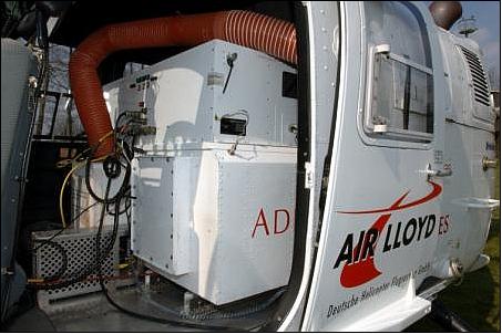
CHARM is an infrared airborne Lidar instrument flown on a helicopter. The German instrument was jointly developed by DLR, Adlares GmbH, and E.ON Ruhrgas AG. E.ON Ruhrgas is Germany's leading gas company and the largest natural gas importer in Europe. It operates a high-pressure gas transmission system totalling some 11,200 km of pipeline. CHARM is owned and operated by E.ON Ruhrgas. 1) 2) 3)
CHARM is inspecting the natural gas pipelines by monitoring methane from a BO-105 helicopter at a rate of 50 km/hr. CHARM is based on the DIAL (Differential Absorption Lidar) principle, an established active remote sensing method for detecting different gases in the atmosphere. The instrument transmits pulses of light towards Earth, and then receives the radiation that is reflected back from Earth's surface, again in pulse form. Whenever one of these pulses encounters methane, its signal strength is attenuated which implies traces of methane are present in the laser path.
CHARM is able to target the pipeline accurately thanks to an automatic tracking system that combines relevant flight movement information with pipeline position data. The system distributes laser spots within an adjustable corridor by means of an inclined off-axis rotating mirror.
The CHARM instrument, installed on its carrier aircraft, has conducted demonstration flights since 2005. The monitoring method has been certified by the DVGW (German Gas Association) as well as by the EASA (European Aviation Safety Agency).

CHARM-F (CO2 and CH4 Atmospheric Remote Monitoring-Flugzeug)
Within the CHARM program of DLR, CHARM-F represents another instrument development, to be flown on an aircraft at high altitudes. CHARM-F relies largely on the same technology as its predecessor, CHARM, but has nevertheless different objectives, namely relating to climate science instead of operational pipeline monitoring. CHARM-F will also serve as a technology demonstrator for MERLIN (Methane Remote Sensing Lidar Mission), a collaborative spaceborne project of DLR and CNES, planned for launch in 2014. 4)
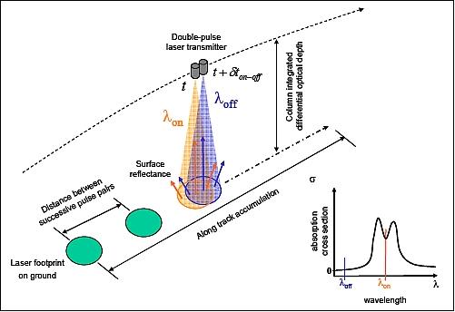
The CHARM-F lidar instrument consists of an IDPA (Integrated Path Differential-Absorption) type lidar with altimeter capability (Figure 2). The IDPA lidar technique is thought to have to br able to close the gap thanks to a truly global coverage with a sufficient spatial and temporal resolution for a more accurate knowledge of the location, magnitude and variability of carbon sources and sinks. 5)
The lidar measures the light scattered and reflected from the Earth’s surface and cloud tops which are illuminated by two laser pulses having slightly different wavelengths denoted as λon and λoff. The online wavelength λon is accurately positioned to the trough of one of the CH4 absorption line multiplets in the 1.64-1.67 µm region. For CO2, the online wavelength is positioned at 1.57 µm.

Measurement principle: IPDA lidars make use of the strong lidar echoes from the Earth’s surface or cloud tops at two wavelengths in the vicinity of a gas absorption line: one so-called “online” channel close enough to the line that significant absorption takes place (λon), one so-called “off-line” channel far enough that negligible absorption takes place (λoff).
The measurement at λoff serves as the reference measurement with negligible CH4 absorption. From the ratio of the lidar echoes of both signals, the differential optical depth and with that the column-averaged CH4 volume mixing ratio can be calculated. From analyzing the waveform of the backscattered pulses, information on the vegetation height with respect to the ground, cloud boundaries, and strong aerosol layers can be derived with high vertical resolution.
CHARM-F Instrument Design
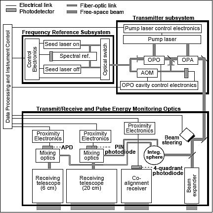
CHARM-F consists of two largely independent and identical lidar systems (one per trace gas), each including one Frequency Reference subsystem, one Transmitter subsystem, and one set of Transmit/Receive/Pulse Energy Monitoring Optics and detection chains (Figure 3).

Transmitter Subsystem
Each transmitter subsystem includes a pump laser and a frequency conversion stage. The pump lasers are two identical double-pulse, Q-switched, diode-pumped Nd:YAG lasers developed by the Fraunhofer Institute for Laser Technology (ILT), delivering double pulses at a pulse-pair frequency of 50 Hz with an inter-pulse delay of 250 µs, corresponding to a footprint co-registration of better than 0.1 m.
The frequency conversion stages, developed at DLR, make use of a MOPA (Master Oscillator/Power Amplifier) architecture. Single-mode operation at the required online and off-line wavelengths with high spectral purity is achieved by injection seeding of the OPO (Optical Parametric Oscillators). Both the OPO and the OPA (Optical Parametric Amplifiers) are pumped by the same pump laser; the non-linear material of choice for both is KTA (KTiOAsO4, or Potassium Titanyl Arsenate). Continuous tuning of the OPO cavities to the seeding wavelengths is achieved by monitoring the beat note between the outgoing pulses and a frequency-shifted portion of the seeding light, in a similar way to the WALES (WAter vapor Lidar Experiment in Space) system.
In parallel to the MOPA developments at DLR, a solid-state laser with Erbium-doped laser crystal for direct generation of the required wavelength is under investigation at ILT as an alternative transmitter technology. The expected benefits are a very high spectral purity and excellent beam profile.
FRS (Frequency Reference Subsystem)
Each FRS includes a set of continuous-wave lasers dedicated to injection seeding of the OPO, suitable spectral references for frequency-locking the seed lasers at the required frequencies, and a fast telecom-type optical switch for alternatively seeding the OPO with the on-line and off-line seed laser in a synchronized way with the pulse pairs.
For CH4, distributed feedback laser diodes deliver the seeding radiation while for CO2, fiber lasers provide the “cleaner” behavior (linewidth < 5 kHz, good short-term stability) required for precise and reliable locking at the sub-100 kHz level. Currently investigated locking methods include the combined use of a tunable, relative spectral reference with sharp spectral features and good short-term stability such as a temperature-stabilized confocal Fabry-Pérot Etalon and an absolute reference - multipass absorption cell filled with low-pressure CO2 or CH4 - for locking the relative reference itself.
The development of this subsystem was greatly facilitated at DLR by a GPS-stabilized frequency comb (FC-1500, Menlo Systems), serving as an absolute reference with an estimated long-term stability of 500 Hz for realtime monitoring of the performance of the investigated stabilization schemes.
Transmit/Receive Optics and Detectors
Nine optical heads are accommodated on an optical bench above one of HALO’s 50 cm floor windows: one beam expander and two receivers per trace gas, plus one co-alignment receiver and two contextual cameras (not shown on Figure 3).
In the 1.6 µm region, preliminary performance analyses have shown that a small receiving entrance aperture of 6 cm was sufficient in combination with off-the-shelf InGaAs APDs (Avalanche Photodiodes) with a suitable bandwidth for the required ranging precision. A significant drawback of InGaAs APDs, however, is the currently limited available active diameter, a mere 0.2 mm. This, together with the large required field of view, drives the f/number of the receiving optics towards a challenging value of slightly less than 1.
Considering the increased impact of pulse-to-pulse pointing and/or footprint size variations with such tight margins, it was decided to implement a second receiver built around a PIN photodiode with an active diameter of 1 mm. A larger aperture of 20 cm is used to partly compensate for the lower detectivity of this type of detector. Both receivers feature a narrow bandpass filter for solar background rejection. They will be used simultaneously during the flight campaigns.
For real-time monitoring of the transmitter/receivers co-alignment and subsequent correction of the pointing drifts via beam steering, an additional receiver with four-quadrant photodiode is considered.
Pulse Energy Monitoring Optics
To “calibrate” the measurement of dΔ with the relative outgoing pulse energies corrected for the relative overall optical efficiency, a small fraction of the outgoing beams is sampled out and spatially- and polarization-scrambled by means of an integrating sphere. The sphere also provides further attenuation, so that the sampled light can be measured by the very same photodetector as the backscattered light without the need for an increased dynamic range. Using the same photodetector for both avoids biases linked with unknown discrepancies in the gains and offsets of two distinct detection chains. “Mixing optics” within each receiver merge the backscatter path and the pulse energy monitoring path sufficiently far upstream of the photodetector that critical elements with a spectral response function that is highly dependent on the incident geometry - such as the bandpass filter - are “seen” by the sampled light with the same incident geometry.
CHARM-F on the HALO Aircraft
Plans call for CHARM-F to be flown on DLR's new HALO (High Altitude, LOng-range) research aircraft starting operational services in 2012. HALO is a modified Gulfstream G550 jet providing a range of 9000 km at flight altitudes of 10-15 km. These performance parameters ensure conditions very similar to a spaceborne case, since little CO2 or CH4 absorption takes place above these altitudes.
The objective of the CHARM-F instrument on HALO is to address the following key issues:
• Serving as a demonstrator of the observational principle foreseen in the A-SCOPE mission concept in the 1.6 µm spectral region. A-SCOPE (Advanced Space Carbon and Climate Observation of Planet Earth) is one of ESA's Earth Explorer missions selected for study in 2006. The goal of A-SCOPE is to improve our understanding of the global carbon cycle and regional carbon dioxide fluxes.
• Serving as a demonstrator of the use of active optical instruments for flux inversion of CO2 and CH4 by providing simultaneous measurements of CO2 and CH4 gradients on a regional scale with the required high precision and accuracy.
In addition to the A-SCOPE phase 0 activities, the CHARM-F project builds on the pulsed DIAL (DIfferential Absorption Lidar) heritage at DLR, namely the helicopter-borne pipeline monitoring system CHARM and, more recently, the WALES water vapor DIAL system.

References
1) Axel Scherello, Matthias Ulbricht, Thomas Kern, “Airborne Leak Detector Certified In Germany For Urban Gas Grids,” Pipeline & Gas Journal, August 2010, Vol. 237, No 8, URL: https://web.archive.org/web/20110107010421/http://www.pipelineandgasjournal.com/airborne-leak-detector-certified-germany-urban-gas-grids?page=show
2) Werner Zirnig, “Pipeline Remote Sensing for Safety and Environment - The Projects CHARM and PRESESE,” 3rd European Forum Gas 2005, 20-21 September 2005, Warsaw, Poland, URL: http://www.gerg.info/publications/confer_papers/2005/zirnig_warsaw05.pdf
3) Werner Zirnig, Matthias Ulbricht, Andreas Fix, Hans Klingenberg, “Helicopter-borne Laser Methane Detection System - A New Tool for Efficient Gas Pipeline Inspection,” IGRC (International Gas Research Conference) 2004, Vancouver, Canada, November 1 – 4, 2004, URL: http://www.gerg.info/publications/confer_papers/2004/zirnig_vancouv04.pdf
4) DLR, Sept. 8, 2010, URL: http://www.dlr.de/en/desktopdefault.aspx/tabid-3228/5011_read-22638/
5) Mathieu Quatrevalet, Axel Amediek, Andreas Fix, Christoph Kiemle, Martin Wirth, Christian Büdenbender, Sebastian Schweyer, Gerhard Ehret, Dieter Hoffmann, Ansgar Meissner, Jens Löhring, Jörg Luttmann, “CHARM-F: The Airborne Integral Path Differential Absorption Lidar for Simultaneous Measurements of Atmospheric CO2 and CH4,” ILRC 25 (25th International Laser Radar Conference), St. Petersburg, Russia, July 5-9, 2010