EcoSAR (Aircraft-borne polarimetric and interferometric P-band SAR)
Airborne Sensors
EcoSAR (Aircraft-borne polarimetric and interferometric P-band SAR)
Overview Instrument Flight campaign References
EcoSAR is an advanced airborne polarimetric and interferometric P-band SAR (Synthetic Aperture Radar) instrument in development at NASA/GSFC through NASA's IIP (Instrument Incubator Program). The objective is to provide unprecedented two- and three dimensional fine scale measurements of terrestrial ecosystem structure and biomass. These measurements directly support the science requirements for the study of the carbon cycle and its relationship to climate change, recommended by the National Science Foundation's Decadal Survey (2007) and highlighted in NASA's Plan for a Climate-Centric Architecture (2010). 1) 2) 3)
Science requirements: EcoSAR will be capable of providing estimates of canopy height at 1 m resolution and estimates of above-ground woody biomass to an accuracy of 20 Mg/ha (Megagram/hectare) or 20%. The instrument will also be able to map areas of forest extent and areas of disturbance. The finest resolution of the EcoSAR data will be at 0.5 m in the azimuth and 0.75 in the slant range. In addition to quantifying biomass, ecosystem structure, extent disturbance and recovery, the EcoSAR instrument will also be able to perform mapping of ice sheets, ice dynamics and thickness, permafrost depth, flux and storage of water, which is directly in line with Decadal Survey objectives. 4) 5)
Instrument science rationale:
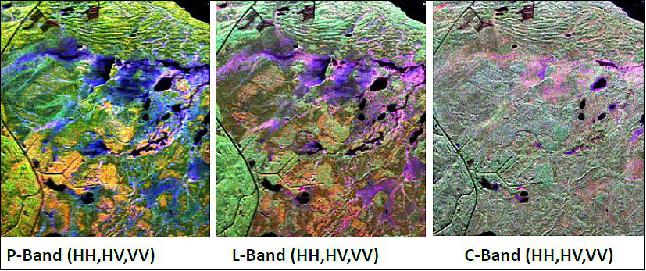
• P-band SAR penetrates vegetation structure allowing the sensing of the entire canopy volume and woody density -> directly related to above-ground biomass.
• Polarimetric radar is sensitive to the shape, orientation and dielectric properties of scatterers -> allows identification and separation of the scattering mechanisms.
• InSAR is highly sensitive to the spatial variability of vertical structure parameters -> 3D height measurements
• Pol-InSAR provides measurements that will allow us to separate ground from canopy -> canopy height.
Sensor Complement
EcoSAR will employ electronic beamsteering on transmit and digital beamforming on receive similar to that proven by DBSAR (Digital Beamforming SAR), permitting the implementation of advanced imaging techniques which overcome problems inherent in conventional SAR systems.
The EcoSAR architecture will allow considerable measurement flexibility such as post processing synthesis of multiple beams, simultaneous measurement over both sides of the flight track, and variable incidence angles (Figure 2).
Beams can be processed with different beamwidths and side lobe levels to control swath widths and minimize side lobe contamination. Ambiguities in the receiver signal can be suppressed by post processing by appropriate nullsteering of the antenna pattern.
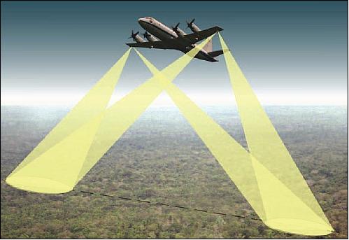
EcoSAR operates at a center frequency of 435 MHz (69 cm wavelength) and features a fully programmable bandwidth over a 200 MHz range. Operational modes with slant range resolutions from 5 m (30 MHz bandwidth) to 25 m (6 MHz bandwidth) are being used as a nominal mode in frequency restricted areas, and a science mode with slant range resolutions as fine as 0.75 m (up to 200 MHz bandwidth) is employed in authorized or remote areas.
EcoSAR architecture:
• RDU (Radar Digital Unit) generates multiple independent waveforms with programmable phase and amplitude.
• RDU acquires and processes radar returns.
• DBF (Digital Beamforming) is performed on board or off line.
• Multiple radar channels enable full polarimetry, standard and ping pong InSAR modes, and cross-track scanning over a wide range of angles.
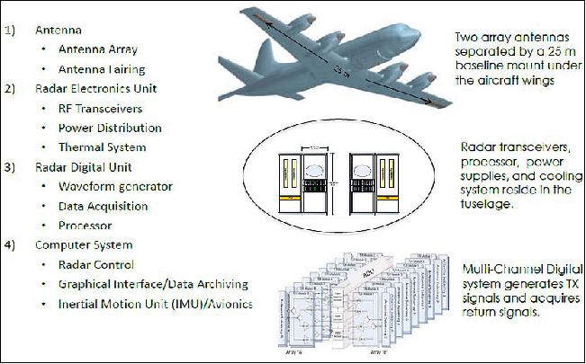
• Two wing-mounted antenna arrays form a 25 m Interferometric baseline.
• 3 IMU (Inertial Measurement Unit) systems measure acceleration, angular velocity, and position at the wings and fuselage.
Parameter | Value | Parameter | Value |
Center frequency | 435 MHz (P-band) | Pulse width | 1-50 µs |
Maximum bandwidth | 200 MHz | Array peak power | 40 W |
Polarization | Polarimetric | PRF | 100 Hz -10 kHz |
Polarization isolation | < -25 dB | Swath per beam | 4 km (from 8 km altitude) |
Single look azimuth resolution | 0.5 m | Number of beams | Multiple |
Slant range resolution | 0.75 - 25 m | Total number of channels | 36 (18 x 2 arrays) |
NESZ (Noise Equivalent Sigma Zero) | < -41 dB (35o incidence angle, form 8 km altitude) | Antenna dimensions | 3 m x 1 m |
Interferometric baseline | 25 m on NASA P3 aircraft | Antenna gain | 20 dB |
Vertical accuracy | 1 m | Number of subarrays | 9 per antenna |
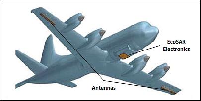
EcoSAR will perform cross-track interferometry in either "standard" mode or in "ping pong" mode employing two array antennas. The antennas will have dimensions of 3 m x 1 m and will be mounted under the aircraft wings (Figure 3). This configuration will provide a 25 m baseline in standard mode and a 50 m baseline in "ping-pong" mode. These baselines are a small fraction of the critical baseline, therefore, minimizing any decorrelation due to the baseline.
Note: In ping-pong mode, the radar transmits alternatively out of the two antennas and receives the radar echo only through the same antenna. RTIs (Repeat-Track Interferometers) are inherently operating in "ping-pong" mode. 6)
Antenna arrays:
• EcoSAR employs two antennas installed externally to the P3 aircraft under the wings.
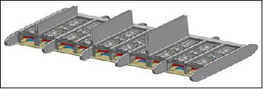
• Each antenna is made up of 10 identical subarrays.
• The antenna elements required a custom (in-house) design to meet EcoSAR's bandwidth, polarization, and scan requirements.
• The element design adopted is based on stacked patch approach using a process of modeling, simulations, prototyping, and testing which led to the final element.
Parameter | Value | Parameter | Value |
Antenna type | Stacked patch | Scan angle | ± 35o |
Center frequency | 435 MHz | Cross polarization isolation | >30 dB |
Maximum bandwidth | 200 MHz | Number of subarrays | 10 |
Gain | 19 dB | Total number of elements | 20 |
Polarization | Dual, linear | Dimensions | 3 m x 1 m |
The EcoSAR antenna elements will be based on a new microstrip design approach which increases bandwidth and cross-polarization isolation. Antenna element simulations have demonstrated to support 50% bandwidth and polarization isolation better than 25 dB. The EcoSAR antennas are being designed and fabricated by the Aerospace Department at the University of Kansas. The two antenna arrays have dimensions of 3 m x 1 m x 19 cm.
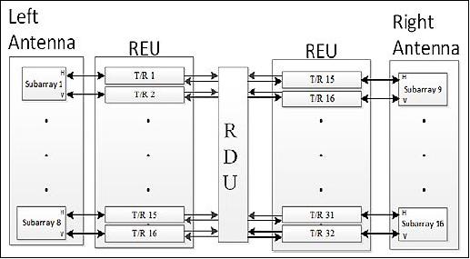
The antenna arrays will be connected to a REU (Radar Electronics Unit) which resides in the aircraft fuselage; it includes 32 dual-polarity T/R (Transmit/ Receive) modules. The T/R modules will equipped with 20 W SSPAs (solid state power amplifiers), LNAs (Low Noise Amplifiers), circulators, couplers, filters, and control switches, as illustrated in Figure 5. They will also include closed loops for robust calibration, dynamic beam control and adaptive waveform generation.
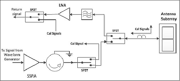
The analysis on the types of architectures that best suit the EcoSAR system led the project to select a hybrid design where the transmitter portion of the transceiver will be realized using connectorized components, while the receiver will be designed on a PCB (Printed Circuit Board) with surface mount components. This approach yields the optimum performance in terms of power, size, and efficiency.
DEU (Digital Electronics Unit):
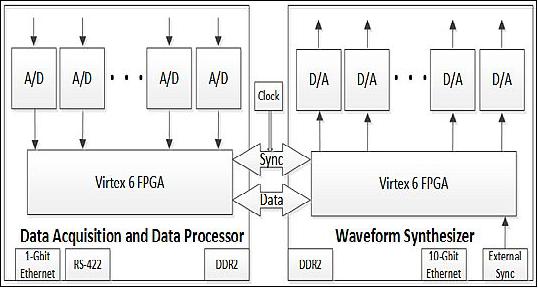
EcoSAR features an FPGA-based programmable digital waveform synthesizers system with 32 time-synchronous and phase-locked digital waveform generators (with independent amplitude and phase control), and a reconfigurable data acquisition and real-time processor with 32 independent receive channels. Figure 7 shows a simplified block diagram for the Digital Electronics Unit.
RDU (Radar Digital Unit):
• 32 channel arbitrary waveform synthesizer for transmit signals, 32 channel acquisition and onboard processor system for the return signals.
• Total of eight V6 FPGA-based mother boards, each board generates or acquires 8 independent waveforms.
• 32 waveform generators directly synthesize arbitrary P-band signals with up to 200 MHz bandwidth.
• 32 acquisition and processing channels sample the radar returns directly and implement onboard Digital I&Q demodulation, filtering.
• Fully programmable through Graphical Interface Unit on host computer.
• 10 Gbit Ethernet data transfers to host computer\raid system.
REU (Radar Electronics Unit):
• 32 transmit/receive (T/R) modules for the conditioning of the transmit and receive signals and for implementation of robust calibration schemes.
• In-house design based on a hybrid approach that employs connectorized RF components for the high power transmit sections and lower power printed circuit board (PCB) for the rest of the module.
• External contracts developed prototype circulators, switches and solid state power amplifiers (SSPA) with 200 MHz BW and 20 W power handling.
- The amplifiers included fast turn on/off for reduction of power consumption and noise leakage.
- The T/R modules are equipped with 20 W SSPA, low noise amplifiers (LNA), circulators, couplers, filters, and control switches.
- The power switching capability of the SSPA enable a relatively simple cooling system based on heat sinks and air cooling.
- Considerations for the mechanical design included physical mounting and vibration isolation, physical isolation of each channel for EMC/EMI purposes, heat dissipation from the power amplifier, physical access to facilitate interconnection, testing and maintenance.
- Final mechanical REU configuration employs the NASA P3 aircraft racks.
The EcoSAR architecture will support full polarimetric operation and a hybrid polarity operation (i.e., transmit circular, receive horizontal and vertical polarizations) for the retrieval of the full backscattering matrix. 7) Orthogonal polarity waveform generation techniques will also be used to implement RFI (Radio Frequency Interference) mitigation techniques.
EcoSAR's digital beamforming, polarimetric, and "single pass" interferometric operation will make this system a first of its kind, providing unprecedented two- and three-dimensional fine scale measurements of terrestrial ecosystem structure and biomass. Terrestrial ecosystems are a crucial component of the carbon cycle, and the greatest uncertainty in the global carbon cycle stems from the estimation of carbon uptake and release by terrestrial ecosystems. EcoSAR will map forest cover, above ground biomass, disturbance due to deforestation and logging, forest recovery, and wetland inundation, closing the gap in understanding the global carbon cycle.
It is expected that the TRL (Technology Readiness Level) of the whole system, as well as its main elements, be at 6 at the completion of the work when the EcoSAR performs flight campaigns.
Flight Campaign
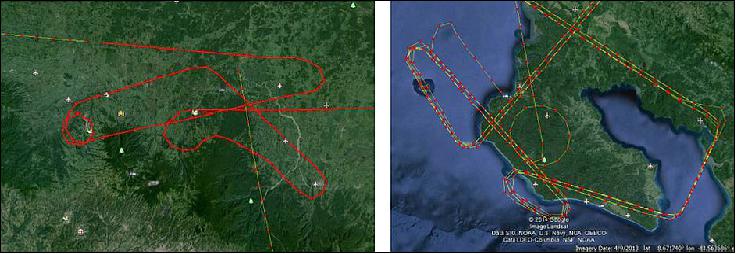
• EcoSAR first test flights and a science campaign were conducted onboard a NOAA-P3 aircraft in March 2014.
• The areas measured with the radar included sections of Andros Island in the Bahamas, and the La Selva and Corcovado National parks in Costa Rica.
• Field measurements over these areas were also conducted during the same month.
Concluding Remarks and Future Plans (Ref. 8):
• The EcoSAR three year IIP development was successful in designing, fabricating and testing the instrument.
• The instrument's first flight campaign was successfully accomplished, generating a large data sets for algorithm development and system performance assessment.
• Current work is focused on RFI removal and robust wide-band beamforming.
• EcoSAR will also serve as a test bed to study advanced beamforming techniques, which will include adaptive waveform generation, orthogonal waveform operation.
References
1) Rafael F. Rincon, Temilola Fatoyinbo, Guoqing Sun, K. Jon Ranson, Martin Perrine, Manohar Deshapnde, Quenton Bonds, "The EcoSAR P-band Synthetic Aperture Radar," Proceedings of IGARSS (International Geoscience and Remote Sensing Symposium), Vancouver, Canada, July 24-29, 2011
2) "Goddard's Growing Radar Capabilities Recognized in Two New Awards," Feb. 8, 2011, URL: http://gsfctechnology.gsfc.nasa.gov/GrowingRadar.html
3) Temilola Fatoyinbo, Rafael F. Rincon, Guoqing Sun, K. Jon Ranson, "EcoSAR: A P-band digital beamforming polarimetric interferometric SAR instrument to measure ecosystem structure and biomass," Proceedings of IGARSS (International Geoscience and Remote Sensing Symposium), Vancouver, Canada, July 24-29, 2011, URL of presentation: http://www.grss-ieee.org/wp-content/uploads/2011/07/EcoSAR-Science-IGARSS11-Presentation.pdf
4) Rafael F. Rincon, Temilola Fatoyinbo, Kenneth J. Ranson, Guoqing Sun, Manohar Deshpande, Richard D. Hale, Arvind Bhat, Martin Perrine, Cornelius F. Du Toit, Quenton Bonds, Victor Marrero, Paul James, "Development of the EcoSAR P-band Synthetic Aperture Radar," Proceedings of IGARSS (International Geoscience and Remote Sensing Symposium), Munich, Germany, July 22-27, 2012
5) Temilola Fatoyinbo, Rafael F. Rincon, Guoqing Sun, K. Jon Ranson, "Using EcoSAR to Measure Forest Structure and Biomass," earthzine, June 29, 2012, URL: http://www.earthzine.org/2012/06/29/using-ecosar-to-measure-forest-structure-and-biomass/
6) Paul A. Rosen, Scott Hensley, Ian R. Joughin, Fuk K. Li, Soren N. Madsen, Ernesto Rodriguez, Richard M. Goldstein, "Synthetic Aperture Radar Interferometry," Proceedings of IEEE, Vol. 88, No. 3, March, 2000, pp.333-382, URL: http://citeseerx.ist.psu.edu/viewdoc/download?doi=10.1.1.24.9675&rep=rep1&type=pdf
7) R. Keith Raney, "Hybrid-Polarity SAR Architecture, 2007," IEEE Transactions on Geoscience and Remote Sensing, Vol. 45, No. 11, pp. 3397- 3404
8) Temilola Fatoyinbo, Rafael Rincon, K. Jon Ranson, Batuham Osmanoglu, Guoqing Sun, Seungkuk Lee, Manohar Deshpande, Martin Perrine, Cornelis Du Toit, Quenton Bonds, Jaclyn Beck, Daniel Lu, Richard Hale, "EcoSAR P-band Digital Beamforming Polarimetric and Interferometric SAR instrument to measure Ecosystem Structure, Biomass and Surface Water," ESTF 2014 (Earth Science Technology Forum), Leesburg, VA, USA, Oct. 28-30, 2014, URL: http://esto.nasa.gov/forum/estf2014/presentations/B4P4_Fatoyinbo.pdf
The information compiled and edited in this article was provided by Herbert J. Kramer from his documentation of: "Observation of the Earth and Its Environment: Survey of Missions and Sensors" (Springer Verlag) as well as many other sources after the publication of the 4th edition in 2002. Comments and corrections to this article are always welcome for further updates (eoportal@symbios.space).