Global Hawk
Airborne Sensors
Global Hawk UAS (Unmanned Aerial System) of NASA
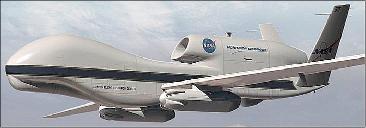
In 2010, NASA is about to begin a new chapter in its Earth exploration science program, as it prepares to fly UAS (Unmanned Aerial Systems) for the first time. The Global Hawk flight system was originally developed for reconnaissance and combat purposes, but Northrop Grumman and NASA engineers managed to convert two planes into a multi-purpose science platform; each platform will be able to provide NASA and NOAA scientists with advanced readings of the planet's atmosphere, in particular for the benefit of Earth's climate programs.
The remotely-controlled airplanes can fly at very high altitudes (up to 20 km) and over considerable distances (up to 20,000 km). A UAS can remain airborne in excess of 24 hours (31 hours max), which is a considerable progress from the science conducted from 'conventional' aircraft until now. Generally, large, manned planes cannot remain in the air for so long without refueling, and pilots need their rest as well, in order to maintain a high level of performance. But these issues are eliminated with the Global Hawk system, whose controllers can change shift seamlessly.
Northrop Grumman Corporation (NGC) originally manufactured the Global Hawk UAS for the USAF (US Air Force). The Air Force transferred the two Global Hawks to NASA in the fall of 2007. In May 2008, NASA/DFRC (Dryden Flight Research Center) at EAFB (Edwards Air Force Base), CA and the Northrop Grumman Corp. of Rancho Bernardo, CA signed a Space Act Agreement to re-fit and maintain three Global Hawks transferred from the USAF for use in high-altitude, long-duration Earth science missions. The contract is a 5-year partnership between NASA and NGC maintaining, modifying, and operating the Global Hawk UAS, valid for the period 2008-2013. 1) 2) 3)
Each Global Hawk UAS vehicle has demonstrated the capability to carry more than 680 kg of payload mass to altitudes up to 20 km. As of 2009, NASA has two Global Hawk UAS units, which are referred to as AV-1 (Air Vehicle-1) and AV-6. NASA is negotiating with UASF to obtain a third aircraft, AV-7. 4) 5)
The main modifications of the NASA UAS consisted of the following items: Installation of a standardized payload interface panel in each payload space. This interface panel provides the services of: power, 1553-based inertial navigation system (INS) data, and C2 (Command & Control) communication signals to each payload. The panel provides the user with a simple, well documented, and functional PnP (Plug-and-Play) interface to the vehicle that applies to all payload spaces.
The Global Hawk is a revolutionary aircraft for science because of its enormous range and endurance at about twice the altitude of commercial aircraft. Operators pre-program a flight path, then the plane flies itself for as long as 30 hours, staying in contact through satellite and line-of-site communications links to a ground control station at NASA's DFRC in California's Mojave Desert.
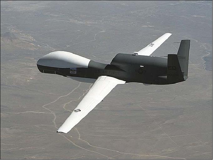
Background: The Global Hawk program has its origins in the 1995 High-Altitude Endurance Unmanned Aerial Vehicle Advanced Concept Technology Demonstration (HAE UAS ACTD) program initiated by DARPA (Defense Advanced Research Projects Agency) and DARO (Defense Airborne Reconnaissance Office). The first seven aircraft were built under the ACTD (Advanced Concept Technology Demonstration) program. The military version of the Global Hawk system has the designation “RQ-4 Global Hawk” - where “R” stands for reconnaissance, “Q” means unmanned aircraft system, and “4” refers to it being the fourth of a series of purpose-built unmanned aircraft systems. 6) 7)
Global Hawk has achieved several distinctions and awards, including setting an endurance record for a full-scale, operational unmanned aircraft on March 22, 2008, when it completed a flight of 33.1 hours at altitudes up to 60,000 feet (18.5 km) over Edwards Air Force Base, Calif. It also set another aviation record on April 23, 2001, when it landed in Australia after a 23-hour, 20-minute trip across the Pacific Ocean. This nonstop flight from Edwards Air Force Base, CA, marks the first time that an unmanned, powered aircraft crossed the world's largest ocean.
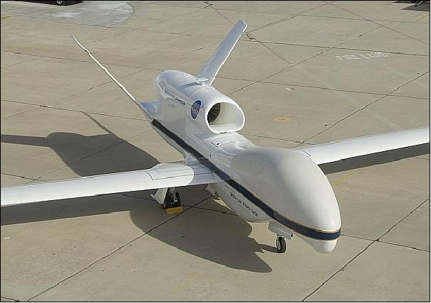
Endurance | > 30 hours |
Range | 20,000 km (> 11,000 nmi) |
Service Ceiling | 20 km (65,000 ft), the instruments are above 94% of Earth's atmosphere at 20 km |
Airspeed (above 17 km, or 55,000 ft) | 560 km/hr or 335 KTAS (Knots True Airspeed) |
Payload mass in one UAS | 450 - 680 kg |
Payload volume available in one UAS | ~ 9.5 m3 |
Payload C3 (Command, Control, and Communications System) | - APCS (Airborne Payload C3 System), and GPCS (Ground Payload C3 System) |
Types of payload compartments | Compartment environmentally controlled |
Payload integration and accommodations | EIP (Experiment Interface Panel & Ethernet Switch), 6 pairs in the aircraft |
UAS length, wingspan | 13.6 m, 36 m |
Ground Segment (Global Hawk Operations Center)
The GHOC is located at NASA/DFRC. It is used to support all ground testing, training, and worldwide flight operations of the NASA Global Hawk aircraft. The main GHOC functions consist in providing C2 (Command & Control) services for the aircraft, monitoring of the aircraft systems, ATC (Air Traffic Control) coordination, mission planning, and all payload-related C2 and data display functions. 8)
Global Hawk Communications Architecture
The Global Hawk is a mid-wing, long-range, long-endurance, single-engine unmanned jet aircraft that typically operates as a fully autonomous vehicle using a comprehensive pre-loaded mission plan. The execution of the mission plan begins when the aircraft is commanded to taxi onto the runway and ends when the aircraft rolls to a stop after touchdown (Ref. 8).
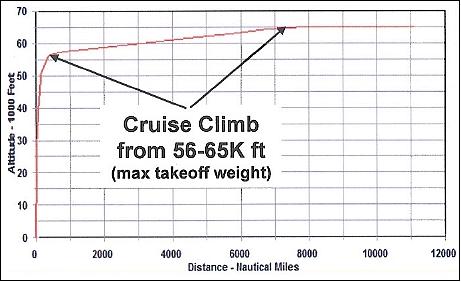
The typical flight profile of the aircraft consists of a rapid climb to approximately 55,000 ft (16.8 km); a subsequent climb at a lower, steady rate as fuel is expended until the aircraft reaches its maximum operational altitude of 65,000 ft (20 km); and flight at maximum operational altitude until the aircraft returns to the operations base and descends for landing.
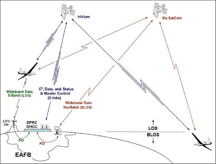
The Global Hawk UAS requires two independent communication links between the GHOC and air vehicle before the start of air vehicle operations. These links permit the (ground) pilot to send commands and receive system status information from the aircraft’s mission computers, and to conduct two-way audio communications with ATC via radios on board the aircraft.
The NASA Global Hawk UAS is operated in two distinct regions: line-of-sight (LOS) and beyond line-of-sight (BLOS) of the UHF (Ultra High Frequency) ground antennas located at DFRC. The communications link used for aircraft LOS C2 is a UHF-band link. The primary communications links used for aircraft BLOS C2 are a primary Iridium Satcom link and a redundant Iridium Satcom link. An Inmarsat Satcom link provides a backup aircraft C2 communications capability. The BLOS ATC bi-directional audio communications between the pilot located in the GHOC and the aircraft are conducted using a primary Iridium Satcom link and a redundant Iridium Satcom link. The aircraft has an onboard UHF/VHF radio set that is used to transmit and receive voice communications between the aircraft and ATC. The use of the Iridium system for aircraft C2 and ATC communications provides complete global coverage, including the Polar regions (Ref. 8) and Ref. 4).
The NASA Global Hawk payload communications links are fully independent of the communications links used to operate the aircraft. Four dedicated Iridium Satcom communication links are used for continuous narrow band communications between the GHOC and the payloads on the aircraft. This narrow band communications capability allows customers to send payload commands from dedicated payload workstations in the Payload Operations Room of the GHOC and receive real-time status and low-rate data from their instruments throughout the duration of the mission. The flight crew uses two additional Iridium links to monitor power consumption by individual payloads, and to control features such as lasers and dropsonde dispensing. - In the meantime, a Ku-band Satcom wideband payload data downlink has been added providing data rates of 40-360 Mbit/s.

Sensor Complement
Science teams from the NASA/ARC, NASA/GSFC, NASA/JPL, NOAA Earth System Research Laboratory (Boulder, Colorado), the University of Denver, and Droplet Measurement Technologies (Boulder, Colorado) are providing the instruments. 9)
- Joint participation in science data gathering missions
- NOAA provides scientific instrumentation to complement NASA instrumentation
- 3-year agreement
- NOAA is also funding the development of a dropwindsonde capability.
Instrument | Objective |
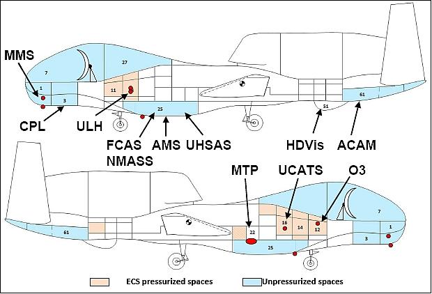
ACAM (Airborne Compact Atmospheric Mapper) | Spectral range: 300-900 nm; Cross-track scanning spectrographs of NO2, O3, and aerosols |
CPL (Cloud Physics Lidar) | Backscatter Lidar for high-resolution profiling of clouds and aerosols |
FCAS (Focused Cavity Aerosol Spectrometer) | Aerosol size and concentration measurements |
MMS (Meteorological Measurement System) | Science quality aircraft state variable measurements |
MTP (Microwave Temperature Profiler) | Passive microwave radiometer measurements of O2 thermal emissions |
HDV (High-Definition Video System) | Time-lapse nadir video color digital imagery with georeferencing |
NMASS (Nuclei-mode Aerosol Size Spectrometer) | Aerosol size and concentration measurements |
Ozone (NOAA UAS Ozone) | Dual-beam UV photometer for accurate O3 measurements |
UCATS (UAS Chromatograph for Atmospheric Trace Species) | Dual gas chromatographs for N2O, SF6, H2, CO, and CH4 measurements |
UHSAS (Ultra-High Sensitivity Aerosol Spectrometer) | Ultra-high sensitivity aerosol spectrometer |
ULU (UAS Laser Hygrometer) | In-situ high-accuracy atmospheric water vapor measurements |
ACAM (Airborne Compact Atmospheric Mapper)
ACAM was designed and built at the NASA/GSFC ( Goddard Space Flight Center) as part of an effort to provide cost-effective remote sensing observations of tropospheric and boundary layer pollutants and visible imagery for cloud and surface information. 10)
ACAM consists of two miniature spectrometers and a high-definition video camera. The spectrometers measure the way sunlight is scattered and absorbed by Earth's atmosphere at hundreds of wavelengths (both visible and invisible). The high-definition video camera is used for visual identification of clouds and features on Earth's surface.
CPL (Cloud Physics Lidar)
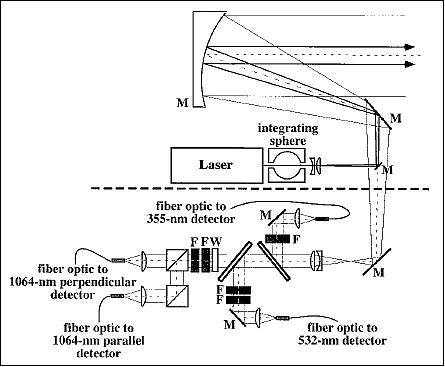
The CPL instrument (successor to the Cloud Lidar System) is an airborne lidar system designed specifically for studying clouds and aerosols. The NASA CPL instrument has been used for validation and simulation of satellite lidar instruments. The CPL operates on the high-altitude ER-2 aircraft, thereby providing an excellent validation and simulation tool for spaceborne lidar instruments. 11) 12)
- In October 2003, CPL provided validation measurements for the GLAS (Geoscience Laser Altimeter System) on the ICESat satellite.
- In 2006, CPL data was used for simulation of CALIPSO (Cloud-Aerosol Lidar and Infrared Pathfinder Satellite Observations) performance and testing algorithms.
- Many non-lidar spaceborne instruments also employ CPL data for validation/calibration purposes. The MODIS instruments on the TERRA and Aqua satellites have utilized CPL data for validation purposes, as has the AIRS (Atmospheric Infrared Sounder) on the Aqua satellite.
CPL is a compact elastic backscatter lidar system that provides multi-wavelength measurements of cirrus, sub-visual cirrus, and aerosols with high temporal and spatial resolution. The instrument provides information to permit a comprehensive analysis of the radiative and optical properties of optically thin clouds (< optical depth 3). The instrument utilizes state-of-the-art technology with a high repetition rate, low pulse energy laser and photon-counting detection.
CPL uses a Nd:YVO4 laser operating at 1064, 532, and 355 nm with a repetition rate of 5 kHz. Use of a low pulse energy, high repetition rate laser permits photon-counting detection while still maintaining an adequate dynamic range for the measurement.
Wavelengths | 1064, 532, and 355 nm |
Laser type, laser repetition rate | Solid-state Nd: YVO4, 5 kHz |
Laser output energy | 50 µJ at 1064 nm; 25 µJ at 532 nm, 50 µJ at 355 nm |
Telescope diameter, type, FOV | 20 cm, off-axis parabola, 100 µrad |
Filter bandwidth | 400 pm at 1064 nm, 120 pm at 532 nm, 150 pm at 355 nm |
Detector efficiency | 3% at 1064 nm, 60% at 532 nm, 10% at 355 nm |
Raw data resolution | 1/10 second; (30 m vertical by 20 m horizontal) |
Processed data resolution | 1 second; (30 m vertical by 200 m horizontal) |
FCAS (Focused Cavity Aerosol Spectrometer)
FCAS counts and sizes aerosol particles by measuring the amount of light scattered as they pass through a laser beam. The instrument consists of a sampling inlet, a Particle Measuring model Focused Cavity Aerosol Spectrometer, and a data acquisition and recording system.
The FCAS III and its predecessor instruments have provided accurate aerosol size distribution measurements throughout the evolution of the volcanic cloud produced by the eruption of Mt. Pinatubo.
MMS (Meteorological Measurement System)
MMS is a NASA/ARC state-of-the-art airborne instrument for measuring accurate, high resolution in situ airborne state parameters (pressure, temperature, turbulence index, and the 3-dimensional wind vector). These key measurements enable our understanding of atmospheric dynamics, chemistry and microphysical processes.
The MMS instrumentation consists of three major systems:
• An air motion sensing system to measure the velocity of the air with respect to the aircraft, i.e., the true air speed.
• An inertial navigation system to measure the velocity of the aircraft with respect to the earth, i.e., the ground speed.
• A data acquisition system to sample, process and record the measured quantities.
The air motion sensing system consists of sensors, which measure temperature, pressures, and airflow angles (angle of attack and yaw angle). The Litton LN-100G Embedded GPS Inertial Navigation System (INS) provides the aircraft attitude, position, velocity, and acceleration data. The Data Acquisition System samples the independent variables simultaneously and provides control over all system hardware.
The MMS is used to investigate atmospheric mesoscale (gravity and mountain lee waves) and microscale (turbulence) phenomena. An accurate characterization of the turbulence phenomenon is important for the understanding of dynamic processes in the atmosphere, such as the behavior of buoyant plumes within cirrus clouds, diffusion of chemical species within wake vortices generated by jet aircraft, and microphysical processes in breaking gravity waves. Accurate temperature and pressure data are needed to evaluate chemical reaction rates as well as to determine accurate mixing ratios. Accurate wind field data establish a detailed relationship with the various constituents and the measured wind also verifies numerical models used to evaluate air mass origin.
MTP (Microwave Temperature Profiler)
MTP is a NASA/JPL airborne instrument. Since the 1970s, variations of the MTP have been deployed 51 times on more than 800 flights in North, Central, and South America; Europe; Australia; the tropical Pacific Ocean; and from the North Pole to the South Pole over the Pacific Ocean.
The MTP uses a passive microwave radiometer to measure thermal emission from oxygen molecules for a selection of elevation angles (normally 10 angles between +60º and -58º). MTP scans forward at various elevation angles both upward and downward from the aircraft. The multiple angles provide it with information on the vertical structure of temperature, which can then be retrieved using a statistical technique which compares the observed set of radiances with those which would theoretically be obtained from a set of reference temperature profiles.
Altitude temperature profiles are obtained once every ten seconds. The temperature field helps scientists identify the height of the tropopause — the boundary between the troposphere (the atmospheric layer closest to Earth), and the stratosphere, where protective ozone is found. Knowing this boundary helps researchers specify the location of the gases and aerosols they measure.
HDVis (High-Definition Video System)
The HDVis camera provides forward-looking time-lapse video imagery from the plane to identify cloud types and provide "situational awareness" for the plane. It has a wide-angle lens and is pointed forward at 45º, so the camera shows everything from the horizon forward to the ground directly below. The view allows the science and operations teams to change course or altitude based on the interesting atmospheric phenomena ahead, and to adjust instrument measurements.
Earlier versions of the video system have flown on missions with NASA's ER-2 and DC-8 aircraft to identify smoke plumes over the Amazon and convective cloud systems in the tropics. This is the first use of high-definition video.
NMASS (Nuclei-mode Aerosol Size Spectrometer)
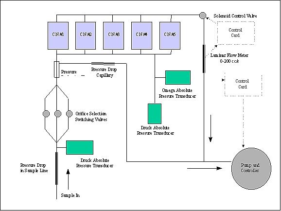
The objective of NMASS is to measure the concentration of particles as a function of diameter from approximately 4 to 60 nm. A sample flow is continuously extracted from the free stream using a decelerating inlet and is transported to the NNASS. Within the instrument, the sample flow is carried to 5 parallel CNCs (Condensation Nucleus Counters) as shown in Figure 7. Each CNC is tuned to measure the cumulative concentration of particles larger than certain diameter. The minimum detectable diameters for the 5 CNCs are 4.0, 7.5, 15, 30, and 55 nm, respectively. An inversion algorithm is applied to recover a continuous size distribution in the 4 to 60 nm diameter range. 13)
The NMASS instrument has a mass of ~43.5 kg, including an external pump. The size is about 38 cm x 41 cm x 80 cm. The power consumption is 350 W at 28 V, including the pump.
Ozone (NOAA UAS Ozone)
Ozone is an instrument of NOAA's Earth System Research Laboratory in Boulder, CO. The objective is to measure ozone through optical absorption. Ozone is a key radiatively active trace gas and is produced photochemically in both the troposphere and stratosphere. In the stratosphere, ozone protects life on Earth from harmful ultraviolet radiation. Halogenated gases released in human activities lead to ozone depletion throughout the stratosphere. Ozone in the troposphere is formed in natural chemical reactions and in reactions caused by the presence of anthropogenic emissions. Understanding how ozone is produced and destroyed in the atmosphere is key to making accurate predictions of future ozone amounts.
The Ozone instrument is a dual-beam ultraviolet (UV) absorption photometer. One beam measures the ozone in air sampled from the atmosphere and the other beam passes through the same air that has had the ozone removed by a scrubber. This provides a reference for the measurement. The entire instrument has a mass of 17 kg (including 1.45 kg for the CompactRIO system), runs on 28 V DC power, and has a variable sample frequency of 0.5 to 10 Hz. The precision is 2 x 10¹⁰ O3 molecules/cm3 with an accuracy of ±5%.
The NI CompactRIO controller provides the processing speeds, low-power consumption, ruggedness and compactness necessary to successfully collect and communicate atmospheric data, unpressurized, at the cruising altitudes of the Global Hawk UAS.
UCTAS (UAS Chromatograph for Atmospheric Trace Species)
UCTAS is an instrument of NOAA's Earth System Research Laboratory in Boulder, CO. The instrument consists of two gas chromatographs (GC) to separate out the different molecules from air, and two absorption photometers to measure ozone (detectable in the ultraviolet) and water vapor (detectable in the infrared). 14)
The objective is to make in situ measurements of the long-lived greenhouse gases like sulfur hexafluoride (SF6), nitrous oxide (N2O), methane (CH4), the halogenated gases (ozone depleting gases) CFC-11, CFC-12, halon-1211, carbon monoxide (important for air quality), and hydrogen. All of these gases are important components for building models of climate change. The instrument separates the different molecules from air. Two absorption photometers measure ozone (detectable in the ultraviolet) and water vapor (detectable in the infrared).
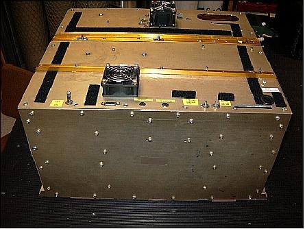
The UCATS enclosure measures 41 cm x 46 cm x 25 cm (W x L x H) and has a mass of 28 kg. The power consumption is 9 A @ 28 VDC (250 W), 16 A (450 W) during warm-up. Earlier versions of UCATS have flown on NOAA, NASA, and NSF (National Science Foundation) missions from 2005 onwards.
UHSAS (Ultra-High Sensitivity Aerosol Spectrometer)
UHSAS is an instrument of Droplet Measurement Technologies (DMT), Boulder, CO. UHSAS measures the concentration and size of atmospheric aerosol particles by collecting air samples and detecting laser light scattered from individual particles in the sample chamber. Aerosols come from natural sources — wildfires, volcanic eruptions, sand storms, etc. — and human sources — such as vehicle and industrial pollution. These particles (0.06 to 1.0 µm in size) play a role in the warming and cooling of the planet by modifying the amount of solar radiation that reaches Earth's surface and returns to space from reflection and emission. 15)
ULU (UAS Laser Hygrometer)
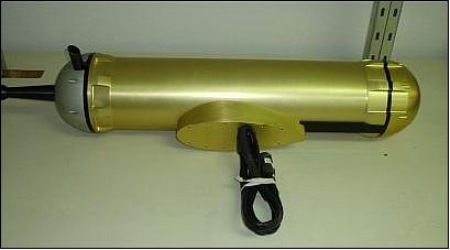
ULU is an instrument developed at NASA/JPL. ULU is an autonomous spectrometer to measure atmospheric water vapor from airborne platforms. The objectives are to monitor the UT (Upper Tropospheric) and LS (Lower Stratospheric) water vapor for climate studies, atmospheric chemistry, and satellite validation.
ULH uses a continuous beam of laser light and two mirrors to sense the amount of water vapor present in packets of air around the plane. These measurements are important because the amount of water vapor in the upper troposphere and lower stratosphere has a disproportionate impact on climate and future climate change. 16)
Global Hawk Campaigns
• Global Hawk test flights within the EAFB range began in October 2009.
• In January 2009, NASA and the NGC (Northrop Grumman Corp.) of Los Angeles have unveiled the first Global Hawk aircraft system to be used for environmental science research, heralding a new application for the world's first fully autonomous high-altitude, long-endurance aircraft. 17)
GloPac (Global Hawk Pacific Science Campaign) 2010
A total of six flights, ranging from 12 to 30 hours in duration will be flown in GloPac 2010. The GloPac flights are designed to address various scientific objectives, including:
- Validation and scientific collaboration with NASA earth-monitoring satellites, principally the Aura satellite
- Observations of stratospheric trace gases in the upper troposphere and lower stratosphere from the mid-latitudes into the tropics
- Sampling of polar stratospheric air and the break-up fragments of the air that move into the mid-latitudes
- Measurements of dust, smoke, and pollution that cross the Pacific from Asia and Siberia
- Measurements of streamers of moist air from the central tropical Pacific that move onto the west coast of the United States (atmospheric rivers).
The flight is the first airborne checkout of the plane took place on April 7, 2010. The aircraft was loaded with 11 science instruments. The data collection objectives are to sample the chemical composition of air in Earth's two lowest atmospheric layers -- the stratosphere and troposphere -- and profile the dynamics and meteorology of both. In addition, observation of the distribution of clouds and aerosol particles. The instruments are operated by scientists and technicians from seven science institutions and are funded by NASA and NOAA. 19) 20)
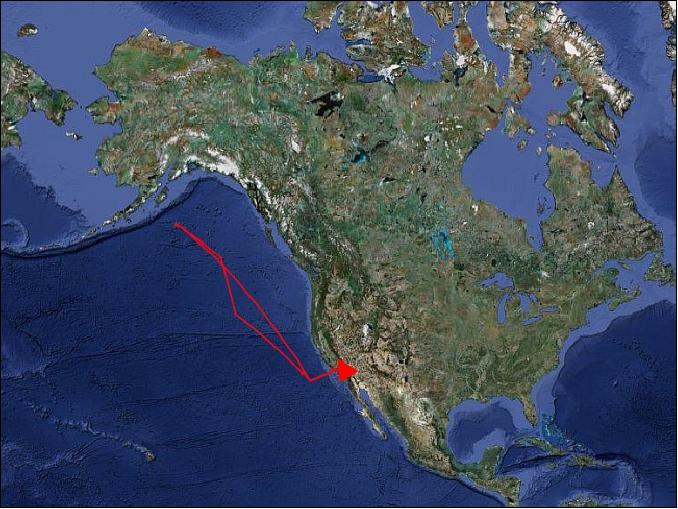
In the GloPac-1 flight (April 7, 2010), the UAS flew approximately 8,300 km (4,500 nautical miles) along a flight path that took it from Dryden to 150.3º western longitude and 54.6º northern latitude, just south of Alaska's Kodiak Island (Figure 13). The flight lasted 14.1 hours and the aircraft flew up to 18.6 km (60,900 ft) in altitude.21) 22)
• During the month of April 2010, the Global Hawk aircraft completed four science flights over the Pacific Ocean. The flights were part of the GloPac mission, a joint project between NASA and the National Oceanic and Atmospheric Administration (NOAA), with Northrop Grumman support. 23)
Long-duration missions will be conducted in the Arctic, Pacific, and western Atlantic oceans. Planned future campaigns are:
• GRIP (Genesis and Rapid Intensification Processes) of tropical storms
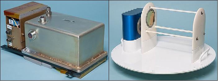
Further Instruments Planned for Flights on the Global Hawk UVS
GOLD (Global Ozone Lidar Demonstrator)
GOLD is a new NASA instrument (not part of GloPac). The GOLD system incorporates advanced laser technology developed, in part, under the NASA Laser Risk Reduction Program (LRRP) to produce a compact, autonomously operating O3 and aerosol DIAL system for a UAV platform. This system also leverages advanced Nd:YAG and OPO (Optical Parametric Oscillator) laser technologies being developed by Fibertek Inc. and ITT Industries under the LRRP and advanced receiver optics and electronics and DIAL (Differential Absorption Lidar) control system technologies developed by NASA/LaRC and Welch Mechanical Designs. All the GOLD subsystems have been integrated and ground tested at NASA/LaRC (Langley Research Center). 24) 25)
The objectives of the GOLD system are to:
- Use the latest technology available to demonstrate the science capability of an O3 DIAL lidar from a UAV platform
- Demonstrate a compact, autonomously operating O3 DIAL system as a precursor to a spacborne DIAL system
- Evaluate new laser technologies for DIAL measurements as they are developed.
The development of the GOLD system was initiated as part of the NASA Earth Science Technology Office (ESTO) Instrument Incubator Program (IIP) in December 2005. Development of the OPO nonlinear conversion modules for generating the O3 DIAL wavelengths of 290 and 300 nm and the aerosol visible wavelength at 532 nm have been completed and lab tested. The initial Nd:YAG laser that was implemented for pumping the OPO is being replaced with a flight proven laser from Fibertek Inc. to improve the alignment stability.
The ITT nonlinear optics module includes the OPO and mixing crystals integrated with the Fibertek Inc. Nd:YAG laser to produce the airborne wavelengths of 290 and 300 nm. The 532 nm second harmonic wavelength of the Nd:YAG laser is used for aerosol profiling; three wavelengths are transmitted in total. An all-metal 40 cm diameter by 40 cm tall telescope has been specifically designed and implemented for the receiver to enable integration into the limited height of the Global Hawk external firing.
Manufacturer | Fibertek Inc., ITT Industries |
Instrument type | Custom seeded Nd:YAG/OPO |
Laser Repetition Rate | 200 Hz (1000 Hz for ITT pump laser) |
Wavelengths | 355, 532, 1064 nm |
Pulse energy | 45 mJ @ 355 nm |
Polarization @ 532 nm | Linear (> 100:1) |
Pulse width | 15 ns |
Telescope diameter | 40 cm |
Full FOV (Field of View) | 1 mrad |
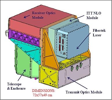
The receiver optics module includes a narrowband grating to simultaneously separate the two UV transmitted wavelengths and narrowband interference filter to reduce solar background light. Also, compact detectors modules that incorporate custom amplifiers, digitizers and data acquisition electronics are integrated into the receiver module. The transmit optics module includes beam expanders, Risley prisms for beam steering, energy monitors, shutters, and optics to set and control the laser output polarization. The dimension of the instrument head shown in Figure 14 is approximately 72 cm x 57 cm x 49 cm.
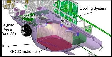
The GOLD system is designed for integration into the lower compartment of the NASA Global Hawk UVS. A drawing for the layout of the GOLD system integrated into the Global Hawk lower compartment is shown in Figure . The GOLD transmitter, receiver, and electronics are housed in a thermally controlled pressure box which is 112 cm x 84 cm x 63 cm in size. For comparison, the overall system parameters for the GOLD instrument and current airborne DIAL systems are listed in Table 2 showing a significant reduction without a loss in performance.
Parameter / Instrument → | UV DIAL | GOLD |
Instrument mass | 1120 kg | 350 kg (420 kg with pressure boxes) |
Power | 10.1 kW | 2.6 kW |
Instrument volume | 3.95 m3 | 0.68 m3 |
Measurements | Nadir/zenith | Nadir |
UAVSAR (Unmanned Aerial Vehicle Synthetic Aperture Radar)
UAVSAR is a reconfigurable L-band SAR instrumentation of JPL which is currently (2010) flown on the NASA Gulfstream III aircraft. NASA plans call for the installation of the UAVSAR into the Global Hawk UAS. The porting of UAVSAR to the Global Hawk UAV will enable long duration/long range data campaigns. The Global Hawk endurance of nearly a day will enable long loiter time over dynamic targets such as volcanoes and earthquakeprone regions for pre-event signature studies or post-event scientific and hazard management activities. 26)
Note: UAVSAR is described on the eoPortal in a separate file.
Frequency | 1217.5 - 1297.5 Mhz (L-band) |
Polarization | Full quad polarization |
Resolution | 1.67 m in range, 0.8 m in azimuth |
Range swath | 22 km |
Look angle | 25-65º |
Antenna baseline | 5.6 m |
Platform | Global Hawk |
Nominal altitude | 13.7 km |
Nominal ground speed | 180 m/s |
Nominal flight duration | 22 hours |
Nominal flight range | 14,500 km |
Implementation of single pass polarimetric-interferometry with UAVSAR instrument onboard the Global Hawk platform encompasses interfacing the two existing UAVSAR pods to the Global Hawk airframe, modifying radar control and timing to synchronize the two radar pods, ground and flight testing, and modifying the UAVSAR ground processor to generate polarimetric-interferometric data products.
References
1) Stephen Cole, Beth Hagenauer, “NASA Debuts Global Hawk Autonomous Aircraft for Earth Science,” Jan. 15, 2009, URL: http://www.nasa.gov/home/hqnews/2009/jan/HQ_09-008_Global_Hawk.html
2) Chris Naftel, “NASA Global Hawk Project, Update and Future, A New Tool for Earth Science Research,” Nov. 16, 2009, URL: http://ntrs.nasa.gov/archive/nasa/casi.ntrs.nasa.gov/20090040628_2009041381.pdf
3) “Global Hawk: High-altitude, long-endurance science aircraft,” January 29, 2010, URL: http://www.nasa.gov/centers/dryden/news/FactSheets/FS-098-DFRC.html
4) Dave Fratello, Dee Porter, “NASA Global Hawk Project Description and Status,” April 7, 2009, URL: http://hsrp.nsstc.nasa.gov/documents/fratello_globalhawk.pdf
5) J. Chris Naftel, “NASA Global Hawk: A New Tool for Earth Science Research,” NASA/TM-2009-214647, May 2009, URL: http://ntrs.nasa.gov/archive/nasa/casi.ntrs.nasa.gov/20090019745_2009018152.pdf
6) http://www.as.northropgrumman.com/products/globalhawk/index.html
7) “RQ-4 Global Hawk,” URL: http://en.wikipedia.org/wiki/RQ-4_Global_Hawk
8) J. Chris Naftel, “NASA Global Hawk: A New Tool for Earth Science Research,” 2009, URL: http://ntrs.nasa.gov/archive/nasa/casi.ntrs.nasa.gov/20090023138_2009019788.pdf
9) http://www.nasa.gov/centers/dryden/research/GloPac/
10) http://www.nasa.gov/centers/dryden/research/GloPac/glopac_instruments.html
11) Matthew J. McGill, Dennis L. Hlavka, William D. Hart, Stephen P. Palm, David M. Winker,, Mark A. Vaughan, Kathy A. Powell, James D. Spinhirne, “The Cloud Physics Lidar and Application to Spaceborne Lidar Validation,” URL: http://ams.confex.com/ams/pdfpapers/85607.pdf
12) Matthew McGill, Dennis Hlavka, William Hart, V. Stanley Scott, James Spinhirne, Beat Schmid, “Cloud Physics Lidar: instrument description and initial measurement results,” Applied Optics, Vol. 41, No. 18, June 20, 2002, URL: http://cpl.gsfc.nasa.gov/papers/CPL_AO_2002.pdf
13) http://cloud1.arc.nasa.gov/solve/payload/dc8/nmass8.html
14) “Unmanned Aircraft Systems (UAS) Chromatograph for Atmospheric Trace Species (UCATS),” URL: http://www.acd.ucar.edu/start/ucats.shtml
15) http://www.dropletmeasurement.com/products/airborne/71
16) http://laserweb.jpl.nasa.gov/ulh/index.html
17) “NASA debuts Global Hawk autonomous aircraft for Earth science,” Jan. 15, 2009, URL: http://www.af.mil/news/story.asp?id=123131528
18) http://www.espo.nasa.gov/glopac/
19) Mike Carlowicz, “First Test Flight,” April 6, 2010, URL: http://earthobservatory.nasa.gov/blogs/fromthefield/category/glopac/
20) http://www.espo.nasa.gov/glopac/people_photo.php
21) Steve Cole, Beth Hagenauer, “NASA's unpiloted Global Hawk completes first science flight,” April 8, 2010, URL: https://web.archive.org/web/20120710220823/http://www.dropletmeasurement.com/images/Global%20Hawk.pdf
22) Mike Carlowicz, “NASA's Global Hawk Completes First Science Flight Over the Pacific,” NASA, April 8, 2010, URL: http://www.nasa.gov/topics/earth/features/global-hawk.html
23) “NASA's UAV Conducts Ground Breaking Science Missions,” Space Daily, June 10, 2010, URL: http://www.spacedaily.com/reports/NASA_UAV_Conducts_Ground_Breaking_Science_Missions_999.html
24) Johnathan W. Hair, Edward V. Browell, Thomas McGee, Carolyn Butler, Marta Fenn, Syed Ismail, Anthony Notari, James Collins, Craig Cleckner, Chris Hostetler, “Development of the Global Ozone Lidar Demonstrator (GOLD) Instrument for Deployment on the NASA Global Hawk,” Proceedings of the ILRC25 (25th International Laser Radar Conference), St. Petersburg, Russia, July 5-9, 2010, pp. 203-206
25) Johnathan W. Hair, Craig Cleckner, Keith Murray, Dave Fratello, Chris Naftel, James Collins, Anthony Notari, Wayne Welch, “Development of the Global Ozone Lidar Demonstrator (GOLD) for the Global Hawk,” Proceedings of the ESTF 2010 (Earth Science Technology Forum), Arlington, VA, USA, June 22-24, 2010, URL: http://esto.nasa.gov/conferences/estf2010/papers/Hair_ESTF2010.pdf
26) Yunling Lou, Roger Chao, Scott Hensley, Cathleen Jones, Timothy Miller, Chris Naftel, David Fratello, “Development of the Aerial Vehicle Synthetic Aperture Radar (UAVSAR) for the Global Hawk,” Proceedings of the ESTF 2010 (Earth Science Technology Forum), Arlington, VA, USA, June 22-24, 2010, URL: http://esto.nasa.gov/conferences/estf2010/papers/Lou_ARRA_UAVSAR_ESTF2010.pdf
The information compiled and edited in this article was provided by Herbert J. Kramer from his documentation of: "Observation of the Earth and Its Environment: Survey of Missions and Sensors" (Springer Verlag) as well as many other sources after the publication of the 4th edition in 2002. Comments and corrections to this article are always welcome for further updates (eoportal@symbios.space).