HUT-2D (Helsinki University of Technology 2D Radiometer)
Airborne Sensors
HUT-2D (Helsinki University of Technology 2D Radiometer)
HUT-2D is an airborne L-band two-dimensional interferometric radiometer using aperture synthesis. The instrument was designed and manufactured at LST (Laboratory of Space Technology) of HUT (Helsinki University of Technology) in cooperation with Ylinen Electronics Ltd., Finland. HUT started the development of this advanced radiometer in the 1990s. The instrument is similar to the MIRAS (Microwave Imaging Radiometer using Aperture Synthesis) instrument to be flown on the SMOS (Soil Moisture and Ocean Salinity) mission of ESA. The HUT-2D project was initially funded by the National (Finnish) funding Agency for Technology and Innovation (TEKES). In late 2000 ESA took over the funding of the project resulting in a successful completion and demonstration of the instrument capabilities. 1) 2) 3)
Note: As of 2005, the Helsinki University of Technology (HUT) gave itself a new acronym, namely TKK (Teknillinen Korkea koulu), using the official Finnish name of the university. However, the renaming has caused considerable confusion among those who were used to the old terminology.
On January 1, 2010, Helsinki University of Technology TKK became a part of Aalto University and was renamed 'the Aalto University School of Science and Technology'. Aalto University was formed by the merger of the Helsinki School of Economics, Helsinki University of Technology and the University of Art and Design. 4)
Background
L-band (1.4 GHz) radiometric measurements are the most promising remote sensing method to retrieve sea surface salinity and soil moisture from space. With conventional technology satellite radiometric measurements with the required spatial resolution of 50 km are not feasible in the near future due to the large antenna size required.
The brightness temperature of soil depends substantially on its moisture content due to the high dielectric contrast between water and dry soil. The total brightness temperature for airborne measurements is the sum of soil and vegetation contributions.
L-band is suitable to soil moisture measurements since the vegetation canopy can be penetrated, depending on the vegetation water content, to provide soil moisture information on the ground below. The optical depth of the vegetation cover must be known in order to retrieve the soil moisture. Additionally, only surface temperature information is required. Soil roughness has a marginal effect to the result.
Sea surface salinity (SSS) is another main parameter for the L-band measurements. For such low frequency measurements wind speed (surface roughness) and the atmosphere (clouds, water vapor) have a rather minimal effect to the brightness temperature. In order to retrieve sea surface salinity with enough accuracy, the effect of sea surface temperature must be eliminated.
The development of HUT-2D started in 1998 and the instrument was finished in its current configuration in 2005. After that, it has participated a number of field experiments, e.g. in the frame of SMOS calibration and validation studies.
HUT-2D Instrument
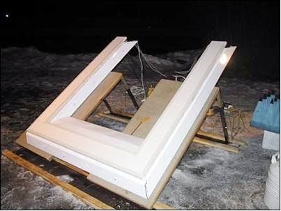
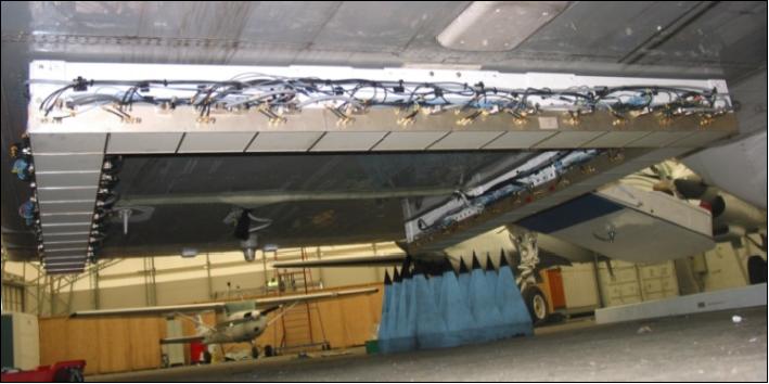
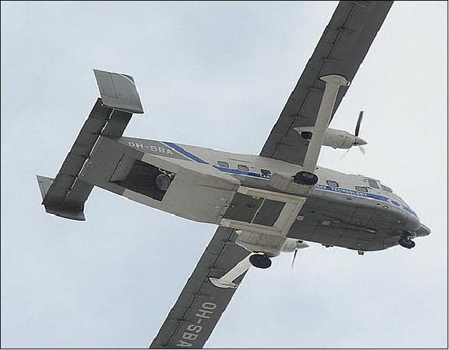
The HUT-2D radiometer instrument consists of 36 receivers, local oscillator subsystem, calibration subsystem and one-bit digital correlator unit as shown in Figure 1. Each pair of receivers (baseline) builds a correlating receiver. The cross correlation of the receiver outputs are processed in the correlator unit. The radiometer has been accommodated below the fuselage of the HUT remote sensing aircraft (Short SC-7 Skyvan) using three specifically designed attachment points. The main instrument specifications are given in Table 1. The selected passband is within the protected band reserved for radioastronomy. 5) 6)
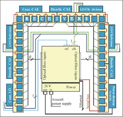
The instrument consists of the following subsystems:
• Antenna / receiver
• RCB (Receiver Control Board)
• Calibration
• Correlator
• Data storage server
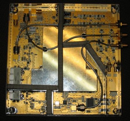
Antenna, RF-board and Receiver Control Board: One antenna, RF-board and receiver control board (RCB) forms a piled integrated receiver packet of size 150 mm x 150 mm x 50 mm. Each integrated receiver is located in a separate shielded housing and the critical sections have further more shielding to avoid all possible internal interferences.
The antenna provides a relatively large beam width (±40º) that covers the whole field of view of the instrument. The antenna matching within the measurement band is better than 20 dB and the coupling between nearest antennas (spacing 0.7 wavelengths) better than -20 dB.
Center frequency | 1.4135 GHz (adjustable within the band from 1400 to 1427 MHz) |
Bandwidth | 7 MHz |
Geometry of instrument | U-shape |
Instrument dimensions | 1.8 m x 1.95 m x 0.15 m |
Number of receivers | 36 (12 per arm) |
Polarizations | H and V (selected by switch) |
No. of baselines | 575 |
Correlator | 1 bit digital - based on field programmable gate array (FPGA) technology |
Sampling rate | 20-60 MHz |
FOV (Field of View), alias free | ± 25º |
Element spacing | 0.7 λ |
Antennas | Dual-polarized aperture coupled microstrip patch |
Synthesized beamwidth | 5-7º (the narrowest beam ever achieved with an L-band airborne radiometer) |
Calibration | Correlated noise injection |
Receiver noise temperature | 350 K ± 20 K |
LO (Local Oscillator) | Nominal 1.4495 GHz, adjustable |
IF center frequency | 36 MHz |
Instrument mass, size | 95 kg, the total size of the instrument without fairings is 2 m x 2 m |
Swath (height = 500 m) | 474 m nadir (boresight pointing) |
Radiometric sensitivity | 0.79 K (at integration time of 4000 ms) |
The receivers are identical conventional superheterodyne total power radiometers with I/Q down conversion added. The total gain is divided between RF and IF blocks. The receivers are integrated in the same printed circuit boards with antenna feeds. For coherent I/Q down conversion all local oscillator signals are locked to the same 5.65 MHz reference signal. The reference signal is produced externally in the correlator subsystem and fed to three local oscillator units.
Instrument Calibration
The instrument calibration is divided into on-ground and on-board calibration. The on-ground calibration consists of the characterization of the calibration subsystem itself and antenna measurements. On-ground calibration results are required when the measured data are converted to the brightness temperature image of the measured target. - The most important on-ground characterization activities are antenna measurements, flat target response measurement and external residual correlation measurements. The flat target response is measured using a known uniform cold target such as open sky.
On-board calibration subsystem: The on-board calibration is performed to solve the receiver parameters. The receiver calibration is based on injecting correlated noise to the receivers. The calibration subsystem consists of: a) a centralized noise unit - one common noise source for all receivers; and (b) three distributed noise units - one noise source for each group of four receivers. In the distributed configuration each receiver can be injected from two different noise sources to provide the overlapping required for the baseline calibration. The objective is to correct the receiver phase and amplitude errors. The 1-bit digital correlator calculates all correlations between the baselines.

Each receiver is connected to the aperture coupled microstrip antenna through the front-end switch. By controlling the switch either horizontal or vertical polarization measurement can be selected. The in-phase (I) and quadrature (Q) outputs are 1-bit digitized and sent to the correlator via optical fibers. The total power is detected from both I- and Q- outputs. The FPGA correlator unit is capable of 3000 real correlations in each integration period. In addition to the baseline correlations (a) the self-correlations (correlation between the same receiver's I and Q output), (b) the all ones and all zeros correlations (between each receiver output and a string of zeros and ones), and (c) several test sequences, are calculated and stored.
An interferometric radiometer requires not only gain and receiver noise temperature calibration but also phase calibration. This means that each receiver's phase delay differences must be calibrated with respect to other receivers. 7)
For both HUT-2D and MIRAS, calibration of the receiver's phase delay differences is based on the distributed correlated noise injection technique, in which a set of calibration diodes is used to provide a coherent noise signal to the receivers. Each diode provides noise signal to a group of receivers, and by overlapping these groups, phase delay differences between any two receivers can be calculated. In addition to the distributed noise injection network, HUT-2D has a centralized noise injection network, in which only one noise diode is used to provide a signal to all the receivers.
Amplitude calibration of an interferometric aperture synthesis radiometer requires calibration of two parameters, namely:
1) the zeroth baseline visibility [u = 0 and v = 0 in (1)] and
2) each receiver's system temperature.
These can be calibrated in the HUT-2D radiometer either by using the centralized noise injection or by measuring known targets. Suitability and comparison of the two methods are to be studied. The noise source of the centralized noise diode is temperature stabilized and provides a stable noise signal. This noise level can be measured, e.g., on ground.
HUT-2D Involvement in SMOS Preparatory Campaigns
In 2006 and 2007, the HUT-2D instrument represented a significant contribution to the SMOS mission preparatory campaigns in providing the first successful airborne demonstration of the complete system. This complex and sophisticated instrument has been used in calibration and validation campaigns to assess retrieval algorithms for soil moisture and ocean salinity. The instrument, even though the antennas are in a different configuration (U-shape vs Y-shape on MIRAS), is very suitable for various verification and validation methods for the MIRAS instrument of SMOS. 8) 9)
• The first ground test of the HUT-2D instrument took place on April 11-12, 2006 at HUT when it was pointed towards Deneb in the Cygnus constellation, a region of high L-band emission of our Milky Way. The radiation from the Galaxy provides a brightness temperature distribution, which is well known at L-band. Especially, the Galactic plane radiates more strongly at L-band than the surrounding regions, as radiative medium is strongly concentrated in the galactic plane. 10)
The actual measurement consisted of a four minute acquisition period. The instrument was turned to the sky and pointed 30º away from zenith to capture the Cygnus area. The measurements were analyzed to address instruments radiometric sensitivity and resolution. The measurement cycle showed that the 9 K brightness temperature differences are (easily) imaged by the instrument.
• The maiden flight test of HUT-2D occurred on May 29, 2006 with the instrument attached to the belly of HUT's Short SC-7 Skyvan aircraft. The aircraft flew over the islands along the southern coast of Finland (in the vicinity of Helsinki) to test the imaging capabilities of the instrument. With relatively simple processing, images of the coastlines were successfully acquired, as well as viewing different terrains and vegetation.
The test flight was conducted to examine the instrument's ability to detect brightness temperature differences, check the operation of calibration and image reconstruction methods, and check for self-interference and interference from the aircraft. The flight route was planned to cross many water-land transitions (high brightness temperature contrast) and some sharp forest-field transitions (low contrast) to determine the instrument's radiometric resolution.
The results show the functionality of the constructed HUT-2D instrument as well as the feasibility of the developed calibration and image reconstruction algorithms. The instrument’s ability to detect high-contrast and low-contrast brightness temperature transitions on the ground was verified by measurements over land-water areas and forested-open areas.
• December 2006 flight. The objective was to test the new calibration unit (temperature regulated centralized noise source) and the updated software allowing fast switching between H- and V-polarization probes (actually they are X- and Y-probes, since the polarization rotates within the image).
• April 2007 - sea surface salinity flight test. The main objective was to find salinity gradients in the coastal zone of the Gulf of Finland, in particular in the vicinity of the confluence of a river. Unfortunately the vessel providing salinity ground truth measurements was not able to detect the large enough variation in salinity. However, this presented to be a good test flight for the August 2007 flight campaign.
• August 2007 - sea surface flight campaign: The CoSMOS flight mission was conducted in cooperation with the TUD EMIRAD (Electromagnetics Institute Radiometer) system and the IEEC/Paris (Institute of Space Studies of Catalonia/PAssive Reflectometry and Interferometry System) instrument. The prime objective was to detect salinity gradients in the coastal zone of the Gulf of Finland near the river Kymi. Altogether there were two SSS (Sea Surface Salinity) flights, each flight making 20 passes over the selected test site. Also one accuracy flight was conducted between the SSS flights for EMIRAD and the HUT-2D instrument to compare the results. 11)
• August 2007 soil moisture flight campaign: Altogether three flight days. First day from Helsinki (southern Finland) to Rovaniemi (northern Finland). Ground truth of soil moisture from southern Finland test sites. Second day: flight in northern Finland over the FMI (Finnish Meteorological Institute) test sites in Sodankylä and Pallas (several different test sites and measured parameters). Third day: flight back from Rovaniemi to Helsinki using the same flight route as on the first day. 12) 13)
In particular, plans call for the HUT-2D instrument to be used after the launch of the SMOS spacecraft to provide ground truth data with coordinated underflights during the commissioning phase of SMOS.
• During spring 2010 the HUT-2D instrument was used to measure three SMOS validation target areas, one in Denmark and two in Germany. 14)
References
1) K. Rautiainen, R. Butora, T. Auer, J.. Kettunen, J. Kainulainen, I. Mononen, D. Beltrami, M. Hallikainen, “Development of Airborne Aperture Synthetic Radiometer (HUT-2D),” Proceedings of IGARSS 2003 (International Geoscience and Remote Sensing Symposium), Toulouse, France, July 21-25, 2003
2) Juha Kainulainen, Kimmo Rautiainen, Matti Vaaja, Martti Hallikainen, “Improved Design for HUT-2D L-band Airborne Interferometric Radiometer,” Proceedings of the 3rd Workshop on Advanced RF Sensors and Remote Sensing Instruments (ARSI), Noordwijk, The Netherlands, Sept. 13-15, 2011, URL: http://www.congrex.nl/11c11/ARSI%20papers/KAINULAINEN_ARSI_Paper.pdf
3) J. Kainulainen, K. Rautiainen, J. Lemmetyinen, J. Seppänen, P. Sievinen, M. Takala, M. Hallikainen, ”Experimental study on radiometric performance of synthetic aperture radiometer HUT-2D – measurements of natural targets, ” IEEE Transactions on Geoscience and Remote Sensing, Vol. 49, No. 2, pp. 814-826, Feb. 2011, ISSN: 0196-2892
4) “Helsinki University of Technology TKK,” URL: http://www.aalto.fi/en/about/history/tkk/
5) Kimmo Rautiainen, Juha Kainulainen, Tuomo Auer, Simo Tauriainen, Juha Lemmetyinen, Pekka Rummukainen, Martti Hallikainen, “HUT-2D measurements during CoSMOS-OS-2 campaign,” 7th SMOS Workshop, Oct. 29-31, 2007, Frascati, Italy, URL: http://earth.esa.int/smos07/pres/21_pres.pdf
6) URL: [web source no longer available]
7) J. Kainulainen, K. Rautiainen, S. Tauriainen, T. Auer, J. Kettunen, M. Hallikainen, “First 2-D Interferometric Radiometer Imaging of the Earth From an Aircraft,” IEEE Geoscience and Remote Sensing Letters, Vol. 4, No. 2, pp. 241-245, April 2007
8) Information provided by Kimmo Rautiainen of HUT, Finland
9) “First images from Finnish radiometer support SMOS,” ESA, Aug. 17, 2006, URL: http://www.esa.int/esaLP/SEMO52Z7QQE_LPearthexp_0.html
10) J. Kainulainen, K. Rautiainen, M. Hallikainen, M. Takala, “Radiometric Performance of Interferometric Synthetic Aperture Radiometer HUT-2D,” Proceedings of IGARSS 2007 (International Geoscience and Remote Sensing Symposium), Barcelona, Spain, July 23-27, 2007
11) M. Talone, R. Sabia, A. Camps, M. Vall-Ilossera, C. Cabarro, J. Font, “Sea surface salinity retrievals from HUT-2D L-band radiometric measurements,” Remote Sensing of Environment, Vol. 114, Issue 8, August 2010, pp. 1756-1764, doi:10.1016/j.rse.2010.03.006
12) Jaakko Seppänen, Martti Hallikainen, Marko Mäkynen, “A soil moisture measurement experiment using HUT-2D aperture synthesis radiometer,” URL: http://www.ursi.fi/2008/data/files/seppanen_URSI2008.pdf
13) Juha Kainulainen, Kimmo Rautiainen, Juha Lemmetyinen, Martti Hallikainen, “Participation of Finnish radiometer HUT-2D in calibration and validation campaigns of European Space Agency’s SMOS mission,” URL: http://www.ursi.fi/2008/data/files/Abstract_URSI_2008_kainulainen.pdf
14) J. Kainulainen, K. Rautiainen, P. Sievinen, J. Seppänen, E. Rouhe, M. Hallikainen, J. Dall’Amico, F. Schlenz, A. Loew, S. Bircher , C. Montzka, “SMOS calibration and validation activities with airborne interferometric radiometer HUT-2D during spring 2010,” Proceedings of IGARSS (IEEE International Geoscience and Remote Sensing Symposium) 2010, Honolulu, HI, USA, July 25-30, 2010
The information compiled and edited in this article was provided by Herbert J. Kramer from his documentation of: ”Observation of the Earth and Its Environment: Survey of Missions and Sensors” (Springer Verlag) as well as many other sources after the publication of the 4th edition in 2002. - Comments and corrections to this article are always welcome for further updates (eoportal@symbios.space).