ISS: OPALS and HDEV
Technology Development
ISS Utilization: OPALS (Optical PAyload for Lasercomm Science) and HDEV (High Definition Earth Viewing)
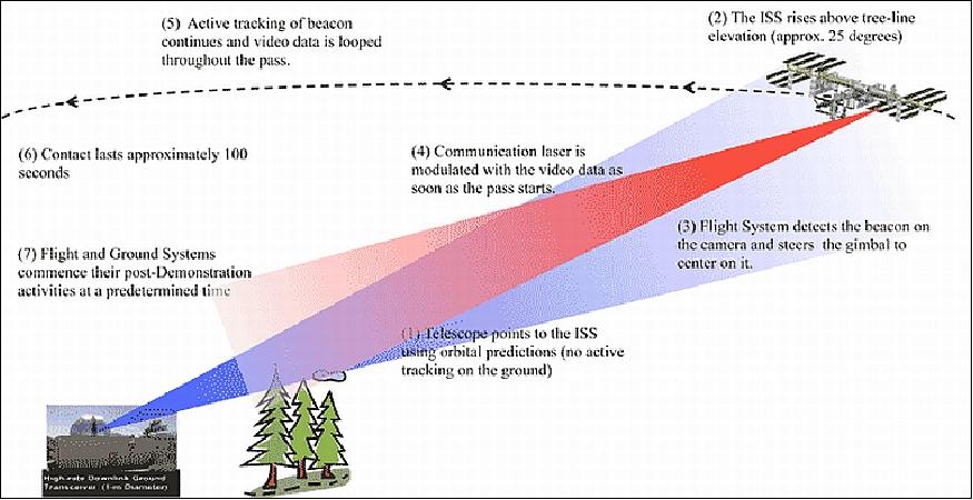
OPALS is a NASA/JPL optical technology instrument to be flown to the ISS (International Space Station) in the spring of 2014. The objective is to demonstrate optical communication by transferring a video from the OPALS payload on the ISS to a ground receiver at JPL's OCTL (Optical Communications Telescope Laboratory) in Wrightwood, California. As the ISS travels across the sky, a laser beacon will be transmitted from the ground telescope to OPALS and be tracked. While maintaining lock on the uplink beacon using a closed loop control system and a two-axis gimbal, the OPALS flight system will downlink a modulated laser beam with a formatted video. Each demonstration lasts for approximately 100 seconds as the ISS payload and ground telescope maintain line of sight. 1) 2) 3) 4)
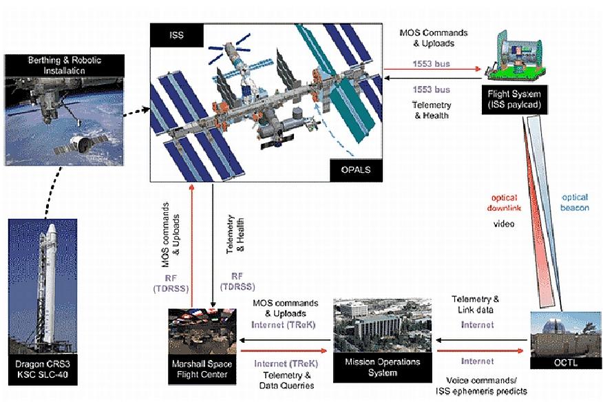
OPALS, which is part of the JPL Phaeton early career employee hands-on training program, aims to demonstrate free-space optical communications technology. During the technology demonstration, a video file from the investigation on the ISS is transmitted to JPL's OCTL (Optical Communications Telescope Laboratory). A digital video file, encoded with forward error-correction to protect against bit errors during transmission, is modulated onto the downlink laser using on-off keying (OOK); a simple form of present vs. absent carrier wave modulation. A beacon-assisted pointing architecture is used to achieve robust and accurate pointing and includes: a camera with a wide angular view used on the ISS investigation to detect the laser beacon transmitted from the OCTL, and an on-board feedback algorithm that actively tracks this beacon as long as line-of-sight is maintained. This enables reliable transfer of the video file in the presence of many disturbances, such as the ISS motion, gimbal jitter, turbulence and background noise. Because the focus of OPALS is to demonstrate end-to-end functionality of an optical communication link, the information transfer rate is chosen conservatively as 10 Mbit/s or higher. 5) 6)
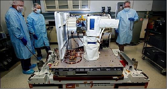
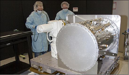
The OPALS flight system refers to the optical communications investigation assembly that is externally-mounted on the ISS. It consists of a gimbal-mounted optical head, and a sealed container to hold the electronics, laser and motor drivers. The optical head houses a camera to track the beacon and a lens collimator system to transmit the data laser. The flight system autonomously detects, acquires and tracks the uplink beacon that is transmitted from the ground telescope as a pointing reference, and uses an on-board feedback system to mitigate external disturbances. The Ground System refers to the receiver system that is located at the OCTL. It utilizes the OCTL 1 m aperture primary telescope to receive the downlink signal and transmit the reference beacon. The received optical signal is acquired and focused onto a photodetector, which converts the optical signal to a baseband electrical current. After digitization, synchronization, error-correction and post-processing, the video file is displayed on a monitor. The OCTL telescope uses ISS orbital predicts, as well as azimuth and elevation profiles to follow the ISS as it traverses its path across the sky.
Launch
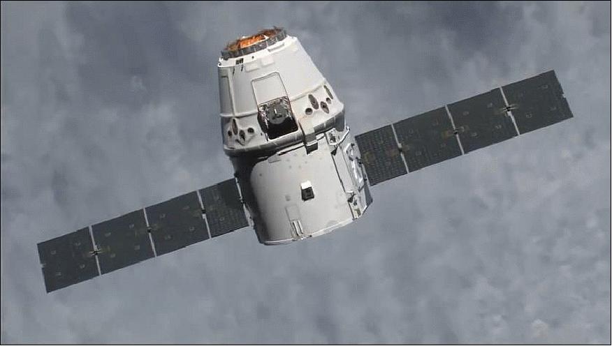
The CRS-3 (Cargo Resupply Services-3) flight of SpaceX was launched on April 18, 2014 (19:25:22 UTC) on a Falcon-9v.1.1 vehicle of SpaceX from Space Launch Complex 40 at Cape Canaveral Air Force Station in Florida. OPALS and HDEF were launched on this third ISS resupply mission. It was the fifth flight for SpaceX's uncrewed Dragon cargo spacecraft and the third SpaceX operational mission contracted to NASA under a Commercial Resupply Services contract. 8) 9) 10) 11) 12)
Orbit: Near-circular orbit, altitude of ~400 km to ISS, inclination =51.6°.
Cargo of CRS-3
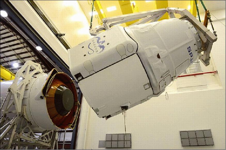
Dragon will be filled with about 2090 kg of supplies and payloads, including critical materials to support more than 150 investigations that will occur during Expeditions 39 and 40. Dragon will carry four powered cargo payloads in its pressurized section and two in its unpressurized trunk, a first for SpaceX.
The Dragon capsule is scheduled to remain attached to the station until May 18. It then will return to Earth and splash down in the Pacific Ocean, off the coast of California. It will return with about 1630 kg of cargo, which includes crew supplies, hardware and computer resources, science experiments, biotechnology, and space station hardware. 13)
The external payloads include:
• OPALS (Optical Payload for Lasercomm Science). The external OPALS payload will test the use of laser optics to transfer information to Earth from space.
• HDEV (High Definition Earth Viewing). The HDEF external investigation includes four high-definition cameras to be placed on the space station's exterior for use in streaming live video of Earth for online viewing.
The science payloads include: 14) 15)
• VEGGIE (Vegetable Production System), a unit capable of producing salad-type vegetables in space. NASA calls to the lettuce 'Outredgeous'. 16) 17)
• Micro-7 (MicroRNA Expression Profiles in Cultured Human Fibroblasts in Space) . Micro-7 is the first spaceflight study of gene and microRNA expression in non-dividing cells. The study also will investigate how spaceflight affects the response of non-dividing cells to DNA damage. 18)
• T-Cell Act in Aging (T-Cell Activation in Aging) experiment that seeks the cause of a depression in the human immune system while astronauts are in microgravity. 19)
• HEART FLIES (Heart Effect Analysis Research Team conducting FLy Investigations and Experiments in Spaceflight). HEART FLIES is the first investigation to use the fruit fly, Drosophila melanogaster, to study the effects of spaceflight on the structure and function of the heart. 20)
• Project MERCCURI (Microbial Ecology Research Combining Citizen and University Researchers on the ISS). A crowdscored mission to send the litany of microbes to the space station for research. The goal of this project was to be a citizen science project and to engage the public as much as possible. 21)
Some hardware deliveries of the CRS-3 flight:
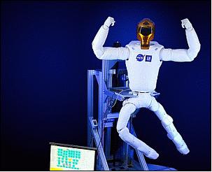
• Legs for Robonaut: After spending three years aboard the Space Station without a set of legs, Robonaut is finally set to receive its high-tech legs built by NASA. Delivered by the SpaceX Dragon, the legs will be installed on Robonaut to enable it to move around aboard the space station. Each leg has seven joints and an End Effector acting as foot used by Robonaut to hold on to handrails and sockets inside and outside ISS. 22)
• EMU (Extravehicular Mobility Unit). The CRS-3 mission will also involve the delivery of a replacement EMU, allowing for the return of a faulty suit on the same vehicle when it returns to Earth. 23)
Dragon SpX-3 will be the first post-Shuttle mission to transfer a complete EMU to and from the Space Station. Although Progress, ATV, HTV and Cygnus spacecraft have been used to transfer EMU hardware, none of these vehicles has transferred a complete space suit. When the Shuttle was flying, the Space Station's EMUs were constantly rotated - units were flown up by the shuttle stowed inside its Airlock Facilities and exchanged with units that were in use on ISS for an extended period of time. This enabled teams on the ground to perform maintenance and servicing the on the EMUs which has a number of advantages that include saving precious crew time and allowing engineers a close-up look at potential problems or damage (Ref. 3).
When the Shuttle was retired, ISS had a set of several complete EMUs and EMU parts aboard for the crew to start performing the normal maintenance and upkeep procedures that include regular battery charging, cooling loop scrubbing and oxygen re-charges/CO2 scrubber replacements as well as detailed inspections and tests.
Riding uphill aboard the Dragon will be EMU-3003 and all of its major components - the Hard Upper Torso, the Primary Life Support System, the Helmet, the Lower Torso Assembly as well as replaceable hardware including gloves and other equipment. To facilitate the EMU, a special rack was built that is installed inside Dragon to support the individual components during launch, entry and landing.
Secondary Payloads of CRS-3
In addition to the primary payload, a Dragon cargo capsule resupply space transport mission to the ISS, the second stage of the CRS-3 Falcon 9 mission carries the following secondary payloads which are contained in four P-PODs (Poly Picosatellite Orbital Deployers). The secondary payloads are part of the fifth installment of NASA's ELaNa (Educational Launch of Nanosatellite) mission. Over 120 students have been involved in the design, development and construction of the CubeSats that will be flown as auxiliary payloads on the SpaceX-3 cargo resupply mission to the International Space Station. 24) 25)
The secondary payloads are not being delivered to the ISS, but will be released from their P-PODs following the separation of the Dragon capsule from the second stage (~10.5 minutes after liftoff). The insertion orbit of the secondary payloads is at an altitude of ~325 km with an inclination of ~51.6º. 26)
The secondary payload missions are described in separate files on the eoPortal (as information is available).
• KickSat, a 3U CubeSat of Cornell University, Ithaca, N.Y., USA. KickSat will carry and attempt to deploy about 250 femtosatellites into LEO (Low Earth Orbit).
• All-Star/THEIA, a 3U CubeSat of COSGC (Colorado Space Grant Consortium).
• SporeSat, a 3U CubeSat (~5.5 kg) developed through a partnership between NASA's Ames Research Center and the Department of Agricultural and Biological Engineering at Purdue University. SporeSat will be used to conduct scientific experiments to gain a deeper knowledge of the mechanisms of plant cell gravity sensing.
• TSAT (TestSat-Lite), a 2U CubeSat developed at Taylor University of Upland, Indiana. The objective is to perform measurements of the temperature and density of the plasma in the near-Earth space environment.
• PhoneSat-2.5, a technology 1U CubeSat of NASA/ARC to continue technology demonstrations of the PhoneSat CubeSat series.
Mission Status
• October 2015: OPALS continues to be a laser sensation. Later this year, researchers hope to use OPALS to help measure platform vibration on the space station, which could provide data that will assist with space station guidance and navigation. The research team will also work with several International Partners to attempt laser transmissions to ground stations in their respective countries. Technology such as OPALS along with additional methods for improving communication between Earth and deep space will provide crew members with the ability to "phone home" on their journeys to Mars and beyond while maintaining performance and morale. 27)
• May 14, 2015: The OPALS instrument on the ISS has been conducting cutting-edge research on data transmission since June 2014. A key technology, called adaptive optics, corrects atmospheric distortions. For the first time, in March 2015, researchers from NASA/JPL used OPALS to demonstrate that the laser signal from the space station can be focused into single-mode optical fibers on the ground. Single-mode optical fiber, with one-quarter the width of a human hair, is the standard in the telecommunications industry. 28)
- In more recent experiments, researchers demonstrated a communications link between OPALS and the ground, using an adaptive optics system. Researchers were able to transmit samples of video through the corrected laser signal and decode it on the ground. "This represents the first demonstration of continuous adaptive-optics correction of a low Earth-orbiting spacecraft-to-ground optical link reported in the open literature," Wright said. "It lays the path for future robust, high-rate optical communications between low Earth-orbit and the ground."
- One of the primary challenges is that laser beams are very narrow, and the OPALS instrument on the space station must be able to very accurately point the laser beam to the receiving telescope on Earth as it travels across the sky. The narrow laser beams and the movement of the space station also mean that even small distortions in the atmosphere can make a big difference in data transmission.
- The space station's fast motion relative to the ground presents an additional challenge, compared to the traditional use of adaptive optics for static astronomical imaging. The adaptive optics instrument, which was provided by Boeing, headquartered in Chicago, uses the laser signal itself, in combination with mirrors and a high-speed camera, to sense the atmospheric differences that distort a signal from space and correct them.
• April 23, 2015: UrtheCast announced that it has teamed with NASA to stream realtime Earth video data from NASA's HDEV (High-Definition Earth-Viewing System) aboard the ISS to UrtheCast's interactive web platform. This summer the live video data feeding will begin from the HDEV cameras to UrtheCast's web platform, its interactive hub of Earth video and imagery. 29)
- The HDEV experiment aboard the ISS was activated April 30, 2014. It is mounted on the External Payload Facility of the European Space Agency's Columbus module. This experiment includes several commercial HD video cameras aimed at the Earth, which are enclosed in a pressurized and temperature controlled housing. While the experiment is operational, views will typically sequence through the different cameras.
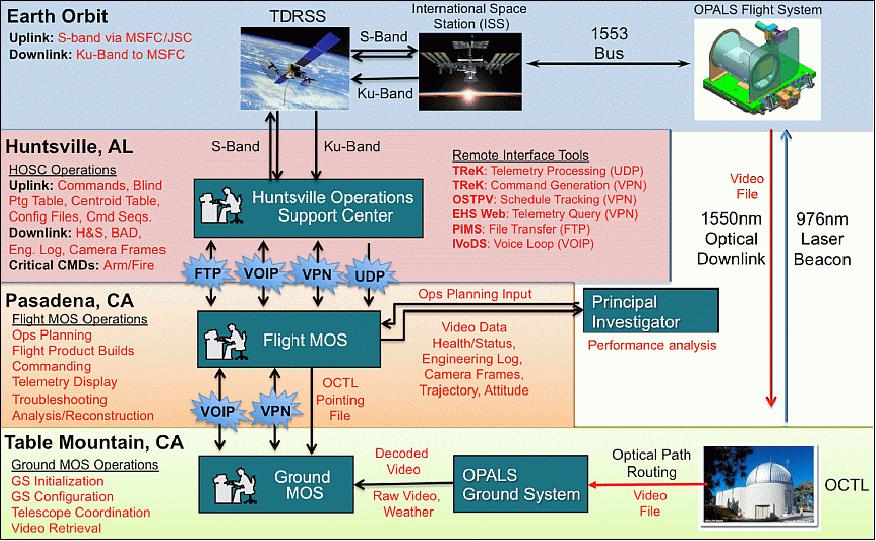
• Between May and October 2014, the OPALS project successfully established 18 optical links from the ISS to the OCTL (Optical Communications Telescope Laboratory) at JPL. The key steps in the procedure have been deploying a flight system (FS) on the ISS, readying a ground system (GS) for the OCTL, implementing a mission operations system — through the Huntsville Operations Support Center at NASA's Marshall Space Flight Center — to coordinate FS and GS operational activities, and conducting link operations. 30)
- During these tests, the project transferred error-free high-definition videos, text files, and test patterns at rates of 50 Mbit/s with a 1550 nm downlink laser. Through the OPALS demonstration, the project achieved the first known direct-detection daytime links from a LEO spacecraft.
- To initiate a link with OPALS, time-stamped predictions are generated for the FS and GS so that they can ‘blind' point to each other. The 976nm laser—transmitted by the GS—illuminates the FS using these predictions. The FS then senses the 976 nm laser by blind pointing the wide-field-of-view CCD camera, which is mounted on a two-axis gimbal. The laser spot image is centered on the camera by controlling the gimbal. This ensures that the downlink laser collimator — co-boresighted to the camera — is pointed back at the OCTL.
• On June 5, 2014, the NASA OPALS demonstration instrument beamed for the first time a high-definition video from the ISS to the OCTL (Optical Communications Telescope Laboratory) ground station of JPL, located at the Table Mountain Observatory in Wrightwood, CA. The transmission of "Hello, World!" as a video message was the first 175 Mbit message of OPALS. Due to the high orbital speed of the ISS (at ~28,000 km/h), the data transmission from the space station to Earth requires extremely precise targeting. The process can be equated to a person aiming a laser pointer at the end of a human hair 10 m away and keeping it there while walking. 31) 32)
- To achieve this extreme precision during the demonstration, OPALS locked onto a laser beacon emitted by the OCTL ground station of NASA/JPL and began to modulate the beam from its 2.5 W laser (1550 nm beam) to transmit the video. The entire transmission lasted 148 seconds and reached a maximum data transmission rate of 50 Mbit/s. It took OPALS 3.5 seconds to transmit each copy of the "Hello World!" video message, which would have taken more than 10 minutes using traditional RF downlink methods.
• On May 18, 2014, the ISS robotics arm (Canadarm2) released the SpaceX Dragon from its grip. The Dragon commercial cargo craft is returning science and cargo for retrieval after its splashdown in the Pacific Ocean. 33) 34)
- While the splashdown of SpaceX's Dragon spacecraft on May 18 will conclude the company's third contracted resupply mission to the International Space Station, it also serves as a high point for the scientists who have investigations returning to Earth who are eager to complete their analyses. 35)
• On May 10, 2014, ground personnel successfully performed the OPALS initial system checkout. This included verification of Health & Status, command capability, file transfer, gimbal activation/calibration, and laser system activation (without laser firing). 36)
• On May 7, 2014, Robotics Ground Controllers successfully installed OPALS on ELC-1 (Express Logistics Carrier-1). 37)
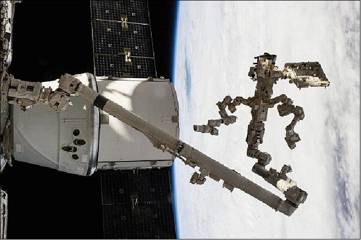
• On May 5, 2014, the robotics team at NASA Mission Control Center at the Johnson Space Center in Houston carefully guided Canada's Dextre robotic "handyman" attached to the end of Canadarm2 to basically dig out the final payload item housed in the unpressurized trunk section at the rear of the SpaceX Dragon cargo vessel docked to the ISS. 38)
• In early May, NASA is now live-streaming views of Earth from space captured by four commercial high-definition video cameras that were installed on the exterior of the ISS in April and became operational on April 30. The experiment, known as HDEV (High Definition Earth Viewing), aims to test how cameras perform in the space environment. 39)
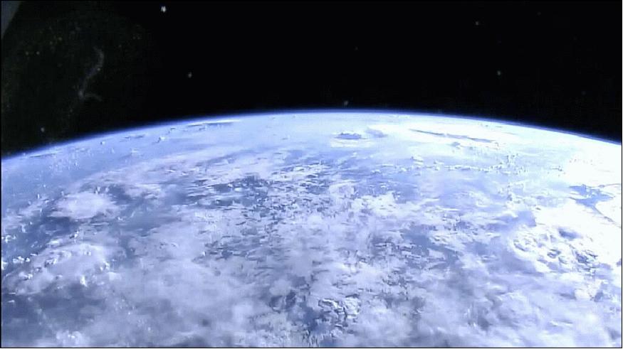
• On April 30, 2014, HDEV was installed and activated on the EPF (External Payload Facility) of the ESA Columbus module. The cameras and electronics are enclosed in a pressurized and temperature controlled box to provide protection to the equipment from the harsh environment of space. HDEV does not record video on board the ISS, but all video is transmitted to the ground in real time. 40) 41)
High school students helped design of some of the HDEV components through the High Schools United with NASA to Create Hardware (HUNCH) program. Student teams will also help operate the experiment.
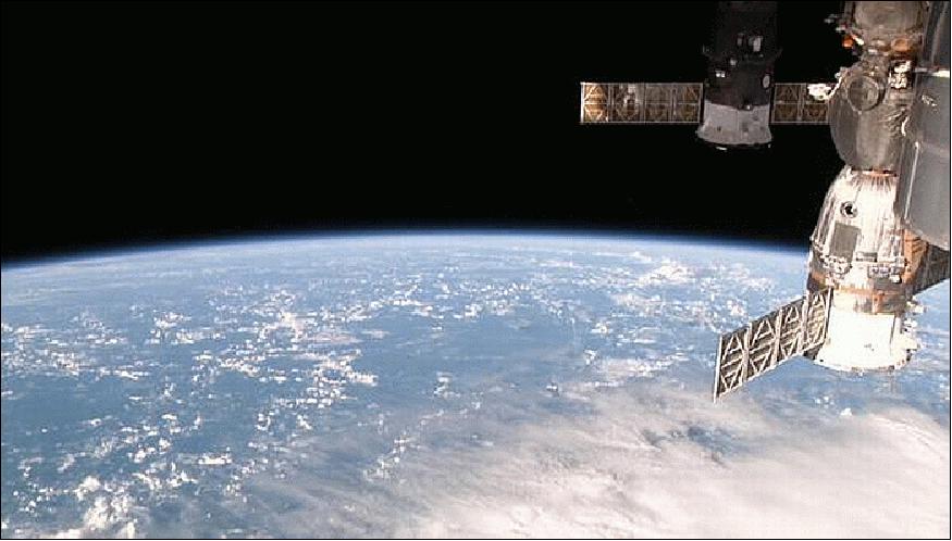
• April 29, 2014: NASA astronaut Steve Swanson joined Koichi Wakata and Rick Mastracchio for more cargo transfers from the SpaceX Dragon commercial cargo craft. Dragon will complete its mission May 18 when it splashes down in the Pacific Ocean carrying cargo and science gear for recovery. 42)
- Robotics controllers are still in the process removing external cargo from Dragon's trunk using Canadarm2 and the SPDM (Special Purpose Dexterous Manipulator). The huge robotic arm with the SPDM (Dextre) in its grasp is removing two external experiments for installation outside the orbital laboratory.
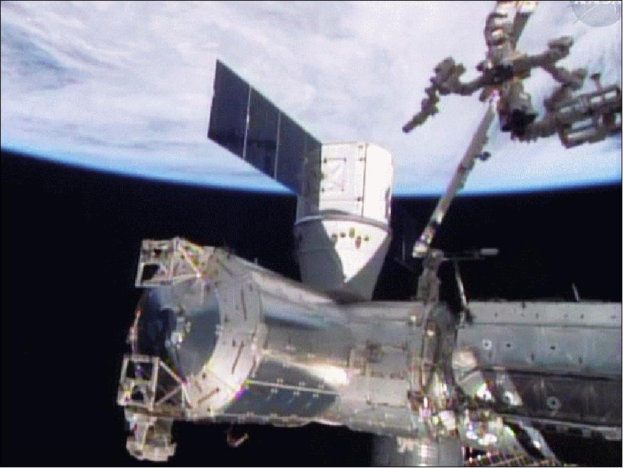
• On April 21, 2014, Expedition 39 has opened the doors to the SpaceX Dragon commercial cargo craft that arrived Sunday morning. The crew has begun unloading the nearly 2.5 tons of cargo including science hardware, a U.S. spacesuit, food and other supplies. 43)
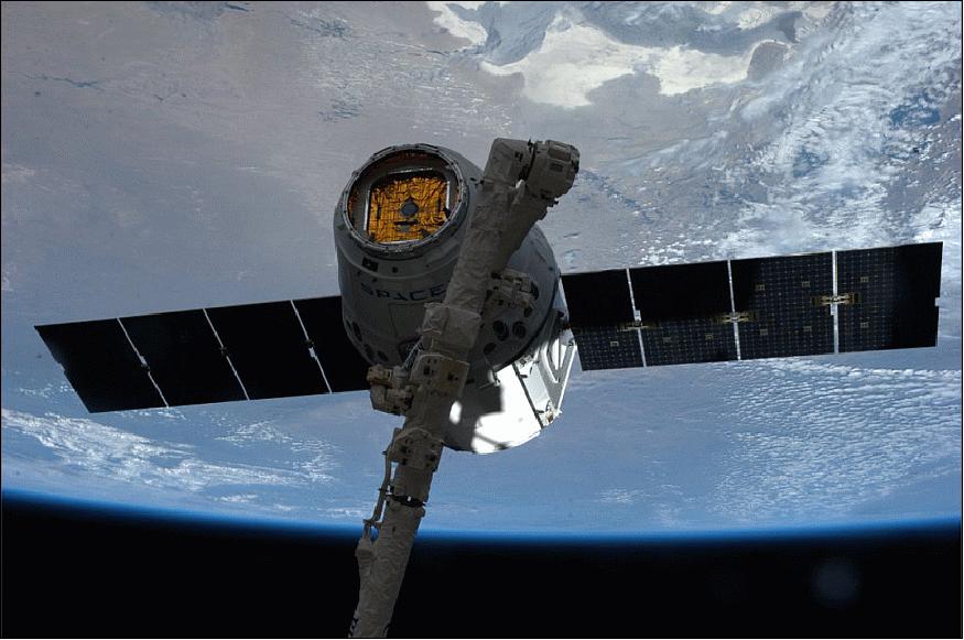
• The SpaceX 3 Dragon commercial cargo freighter successfully arrived at the ISS on Easter Sunday morning, April 20, 2014 as planned and was deftly captured by Expedition 39 Commander Koichi Wakata at 11:14 GMT at the controls of the Canadian built robotic arm (17.6 m long Canadarm2). The Dragon capsule was installed on the Earth-facing port of the Harmony module. 44) 45) 46)
- The crew spent much of the remainder of their workday pressurizing the vestibule between Dragon and the station and setting up power and data cables to prepare for the opening of Dragon's hatch on Monday (April 21, 2014).
OPALS (Optical PAyload for Lasercomm Science) System Description
1) Flight System
The optical flight system is composed of three main elements:
• Sealed Container: houses all of the COTS (Commercial-of-the-Shelf) avionics boards, the laser, and custom power board pressured at 1 atmosphere with air. Connected to the optical gimbal transceiver via cable feedthroughs.
• Optical gimbal transceiver: an optical head that contains an uplink camera and laser collimator for the downlink sits on a two-axis gimbal.
• FRAM (Flight Releasable Attachment Mechanism): both the sealed container and Optical gimbal transceiver sit on the FRAM, which provides a standard mechanical and electrical interface to both the ISS and the launch vehicle.
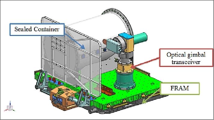
The OPALS flight hardware is a combination of in-house developed hardware and purchased COTS (Commercial Off-The-Shelf ) hardware. The Flight System's primary elements are the sealed container, the gimbaled optical transceiver, and the ExPA-based FRAM. The sealed container houses all electronics (avionics, power, laser) and also maintains 1 atmosphere of pressure to provide forced air cooling of the electronics (similar to convection-cooled fan using a large radiator as a heat dump). The gimbaled optical transceiver is comprised of a two-axis gimbal that holds the optical components essential to establishing the communication link. The ExPA-based FRAM is a standardized and modular platform used for varied purposes on the ISS, one of which is to provide a platform for experiments like OPALS (Ref. 4).
A critical payload feature is the ability to point the laser transmission signal toward the ground receiver. Due to laser safety considerations, the laser transmission cannot radiate the ISS structure. In addition, the OPALS payload is designed to avoid all volumes containing docked vehicles or rotating solar arrays in an effort to reduce dependency on ISS configuration for operations. The resulting implementation is a reduced FOR (Field of Regard), defined as the locus of unit vectors where the gimbal can be pointed. The FOR is approximately 106° wide in azimuth by 36° wide in elevation, with each gimbal axis capped by hard stops and electromechanical limit switches at the travel edges. Figure 13 depicts the alignment of the FOR with the ISS structure. The ISS orientation is typically aligned with the nadir and ram (velocity direction). Therefore, the gimbal azimuth axis is generally aligned with the ISS direction of motion, defining the duration of demonstration periods, while the gimbal elevation axis points starboard, defining the frequency of demonstration opportunities. The asymmetry of the elevation axis has a pronounced effect in that it limits demonstration opportunities to ISS passes north of the OCTL site, assuming nominal ISS attitudes.
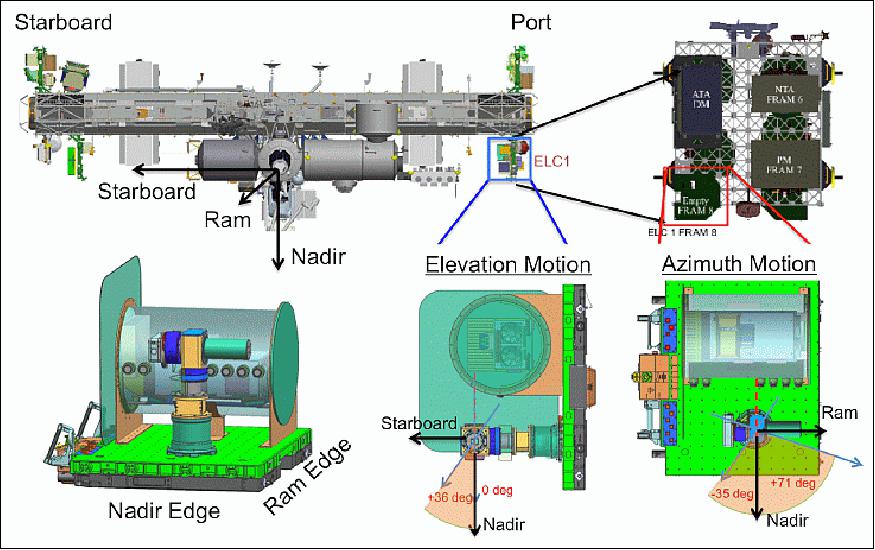
Payload Operational Interfaces
The OPALS payload features command, telemetry, and file transfer interfaces for operations. The sole interface over which packetized data flows to and from the payload is a 1553 bus data connection via the FRAM. OPALS is a command driven payload (with automated and autonomous behavior during a demonstration) that transmits its health and status (H&S) in telemetry at 1Hz, and is capable of bi-directional file transfers between itself and the ISS on command. The payload features a command handler that interprets both real-time commands and sequenced commands. Real-time commands originate from the JPL MSA (Mission Support Area) or the HOSC (Huntsville Operations Support Center), while sequenced commands are stored in onboard files. The payload also features autonomous behavior during the demonstration period when the flight software transitions between a Blind Pointing Table profile and closed loop control depending on beacon detection. For further control during closed loop tracking, a Centroid Deviation Table applies pixel offsets to the centroid target when the beacon is detected.
Commanding
Commanding the payload can occur from the ground or through a set of commands defined in a file located on the payload. Real-time commands are commands that are sent directly from the ground to the payload. A real-time command contains an execution time, which will dictate whether the command is to be executed immediately or at a scheduled time in the future. A command sequence is a set of commands defined in an onboard file that is executed sequentially when activated by a real-time command. All commands in the sequence are scheduled relative to the real-time activation command time. Once received, commands and associated fields are validated for proper syntax
by the command handler. When a command has been validated successfully, it is placed in the command queue for execution as shown in Figure 14.
The command queue, a first-in, first-out buffer, holds all commands waiting to be executed. When a command is popped off the command queue, its execution time is evaluated against the payload computer's system time. If a command is scheduled for a future time, all commands residing in the command queue must wait until the wait time has expired. Only commands to enter safe mode or clear the command queue can pre-empt the execution wait period and clear all commands residing in the command queue.
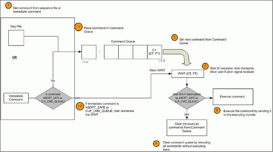
Autonomous Commanding: Blind Pointing Table and Centroid Deviation Table
The OPALS payload can perform autonomous commanding when performing a demonstration. When the command to commence a demonstration is sent, the payload will enter into autonomous behavior by initially entering into open loop search for the beacon, followed by closed loop tracking of the beacon when it has been detected on the camera CCD. A BPT (Blind Pointing Table) is a ground-generated set of azimuth and elevation coordinate positions with an associated relative time at which the gimbal is commanded to point to these positions, relative to the start of a demonstration. The BPT is used for the open loop beacon search and must reside on the payload with a specific file name. Upon command to load the BPT, the file is validated and loaded into memory. Once it has been validated, the BPT profile is interpolated and sampled at the frequency of the feedback control loop. When a Demonstration starts, the gimbal follows the profile specified by the BPT. Once the beacon is detected by the camera, the FSW (Flight Software) will enter into closed loop tracking, no longer being commanded by the BPT but instead being commanded by the closed loop controller.
During closed loop tracking, a loaded CDT (Centroid Deviation Table) is used to apply offsets to the centroid error produced during closed loop tracking. This allows the FSW to lock on to a pixel location offset from the nominal closed loop target on the camera CCD. Since the CDT is sampled at the control loop frequency, it provides the capability to command a time-varying offset profile relative to the nominal closed loop target.
H&S (Health and Status) Telemetry
Health and Status of the OPALS payload is sent to the ground at a frequency of 1 Hz. The H&S telemetry contains critical data regarding the health of the payload as well as the status of safety restraints, command handler status, gimbal pointing angles, laser power, and camera centroid calculations. The FSW sends 750 bytes of H&S data/s to the ISS via the 1553 bus to the ISS. The ISS transmits this telemetry to the HOSC (via TDRS), where it is then forwarded to the OPALS MSA and OCTL. The H&S packet provides the only real-time insight into payload operations, since the detailed onboard engineering log cannot be downlinked until the end of the activity.
2) OPALS Ground System
The OPALS ground system will be at the OCTL (Optical Communications Telescope Laboratory) at the JPL facilities on Table Mountain in Wrightwood, CA. It utilizes OCTL's 1m primary telescope aperture to receive the downlink signal and transmit the reference beacon. The received optical signal is acquired and focused onto a photodetector, which converts the optical signal to baseband electrical current. After necessary digitization, synchronization, error-correction and post-processing, the video file is displayed on a monitor. The OCTL telescope relies on orbital predicts generated by JSC (Johnson Space Center) to follow the ISS as it traverses its path across the sky.
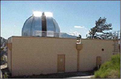
Figure 16 shows a block diagram of the telescope control system. The telescope currently has two CCD cameras that are connected to the control room via firewire-to-fiber optic interface. One camera images the acquisition telescope while the other is attached to a retrofitted motorized zoom lens that can be adjusted remotely in the control room. The zoom lens camera has a 34º x 1.7º FOV. The camera exposure time and gain can be set by the user in the control room. The wide range in field of view is useful when trying to locate objects, especially during field testing. It also simplifies acquisition and tracking of moving objects like airplanes by starting with the zoom camera and a wide field of view; zooming to a narrow field of view; and then handing the tracking to the acquisition telescope camera (Ref. 5).
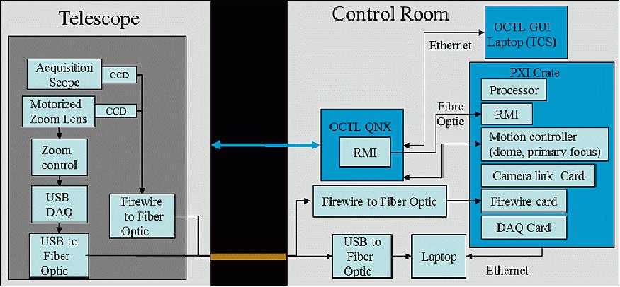
The control room computer systems are designed to allow different experiments to interface to the telescope. The OCTL QNX real time controller is the main processor for the telescope system. It is connected to the OCTL GUI laptop which retains most of the functionality of the original telescope interface. The RMI (Reflective Memory Interfacecard) from the OCTL QNX controller has its mirror in a PXI based real time computer controller. A laptop computer acts as a host to the target PXI system. All commanding and data products flow through this laptop. While the laptop currently sits next to the QNX computer controller, it could be used to operate remotely through an Internet connection.
Besides the computer processor and RMI card, the PXI crate hosts numerous standard interface boards including:
• A motion controller card that drives the telescope primary focus and the telescope dome. Inputs from the OCTL QNX controller allow an auto adjustment of the telescope focus and a dome motion slaved to the telescope azimuth position.
• A cameralink card to control and receive images from an imager
• A firewire card to control and receive images from an imager
• A data acquisition card with analog and digital inputs and outputs.
While the laptop computer can receive any pointing information format and convert it into a telescope azimuth and elevation, the current system can perform state vector tracking with the same format as the original telescope system and sidereal tracking. The telescope can feedback the centroid positions of objects from any of the imagers (zoom, acquisition or main telescope) to center the objects and track them.
Figure 17 shows a functional block diagram used for the LLOT (Lunar Lasercom OCTL Terminal) at OCTL. In this case, the laptop or LLOT controller acts as an overall host for the different sub-systems and data manager for telemetry. Via a TCP/IP protocol it commands a separate computer in the coudé room which locally controls and monitors uplink lasers, the beam divergence zoom system and the variable beamsplitter that splits the light between the tracking camera and the InGaAs camera imager

The PXI processor in Figure 17 reads the InGaAs camera and performs a centroid calculation of the downlink spot. The PXI processor then uses this centroid to center the spot by commanding the FSM (Fine Steering Mechanism). The FSM command signal is also sent to the telescope controller where it adjusts the telescope pointing in order to offload any offset that accumulates on the FSM. Since there is no point ahead mirror in this setup, the telescope itself must point ahead to the spacecraft. The FSM then looks behind with a programmed offset from the LLOT controller. The mission operations center provides a time-stamped file with both the point ahead and look behind coordinates that are read by the LLOT controller.
OPALS system requirements: The OPALS GS will also use a monostatic configuration, receiving 1550 nm from the ISS and transmitting a 976 nm beacon. The wider spectral separation of downlink and uplink made optical isolation on the ground easier. The 976 nm beacon was chosen so that a low cost silicon camera can be used by the OPALS FS. From an atmospheric propagation viewpoint higher wavelengths usually have higher atmospheric transmission and are less vulnerable to atmospheric turbulence. The lower range to the ISS was traded for the lower performance of a 976 nm beacon. The OPALS range is nominally 800 km and both downlink and beacon lasers use wider beam-divergence. Consequently the OPALS flight system (FS) will use a low complexity implementation relying on coarse pointing of a 1 mrad downlink laser with a gimbal. The OPALS beacon is also a multi-beam beacon in order to mitigate turbulence, however, the beam divergence transmitted to the ISS is 1.6 mrad. Transmitting wider beam divergence is more forgiving on pointing and is also less vulnerable to atmospheric turbulence. The OPALS beacon is a continuous wave laser and a combination of higher power transmitted from the ground and spectral filtering on the flight terminal on-board ISS will be used to reject background. The OPALS links also do not involve pointing close to the sun as was the case for LLST (Lunar Lasercom Space Terminal).
The OPALS link will be unidirectional from space-to-ground and will operate at a nominal data-rate of 50 Mbit/s using on-off-key modulation with a Reed-Solomon forward error correction code. The link design for OPALS results in 10's of nW (nanowatt) of downlink power that can be received using commercial detectors and receivers. The decoding will be done using software.
The accommodation of the OPALS FS on the nadir pointed ISS location imposes line-of-sight restrictions due to obstructions and laser safety to avoid irradiating ISS surfaces with 1 W of laser power output by the FS. As a result of this typical OPALS link durations are about 100 seconds. Of course, the slew rates for OPALS GS are much higher than LLOT and can approach 2º/s on near overhead passes.
OPALS optical layout: The optics retrofitted to OCTL for the the OPALS demonstration is shown in Figure 10. Like the OICETS demonstration, this link is made to a LEO (Low Earth Orbiting) spacecraft. The design employs a 20 cm off-axis paraboloidal (OAP) mirror, similar to the approach followed in the OICETS demonstration. The OAP serves both as a mirror for directing the 1.6 mrad beacon through the narrow telescope, as well as transmitting the downlink FOV onto the acquisition camera and the data detector. In this case 4 lasers are co-propagated and the wide beam divergence eases alignment.
The downlink is reflected from the OAP and transmit receive separation is achieved with a dichroic splitter. The downlink is transmitted through the splitter and is incident on a fast steering mirror after which it is split between an InGaAs camera and a commercially available InGaAs avalanche photodiode detector.
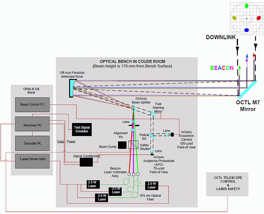
OPALS receiver: The OPALS receiver will use commercially available clock and data recovery (C&DR) circuits to extract the clock from the downlink. The output by the C&DR is digitally stored on a commercial card capable of storing 160 seconds of data at 50 Mbit/s. The stored data files can be processed with decoding software that extracts the data. The OPALS objective is to downlink a video file that is stored in the OPALS FS storage memory. The decoder extracts the video file and can play it back to ensure that the link is working properly. With the Reed-Solomon FEC (Forward Error Correction), an uncoded bit-error rate of < 1 x 10⁻⁴ is needed to receive an error free downlink.
As was done for LLOT real-time monitor and control of the link will be implemented for OPALS. In addition to monitoring the outgoing beacon power, the received power will be sampled at kHz rates and stored so that atmospheric turbulence can be evaluated with post-processing analysis. The status of the C&DR circuit will also be monitored to record any loss-of lock due to link interruptions caused due to deep-fades of other system anomalies.
OCTL laser transmitters: Ground laser transmitters are tailored for each experiment and vary from semiconductor diode lasers to high power solid state laser systems in either a continuous wave (cw) or pulsed mode depending on the link requirements. Ranging applications involved high peak power (> MW/pulse) transmitters such as Q-switched flashlamp pumped Nd:YAG systems to capture returns from retroreflector on LEO or MEO satellites. Multi-beaming is typically used to mitigate the scintillation effects of the atmosphere and also to allow lower power densities on the telescope optics with more readily available sources. For LEO based communication systems, moderate power (0.1 to 10 W) NIR fiber coupled diode lasers prove sufficient as beacon sources under cw or with low rate modulation.
The OPALS project involved four internally wavelength stabilized sources of 2.5 W each at 976 nm operated in cw mode to match the CCD based flight receiver requirements. Due to the broad beam widths, multi-spatial mode sources were sufficient.
The beacon lasers for the LLOT project required much higher powers for the lunar distances with narrower beamwidths. Hence, multiple fiber lasers with single mode output beams were utilized with low rate modulation to give an average laser output power of 60 W (10 W per beam) at 1568 nm. A master oscillator power amplifier architecture for each source was used but instead of the typical high rate modulated seed source, the final amplifier stage had direct modulation of the pump diodes synchronized at 1 kHz, enough for the flight system pointing and tracking quad sensor to lock onto for acquisition. Full monitor and control of the laser was possible remotely from the control room.
3) ISS (International Space Station)
OPALS will be mounted externally on the ISS in a nadir position on an ELC (ExPrESS Logistics Carrier).
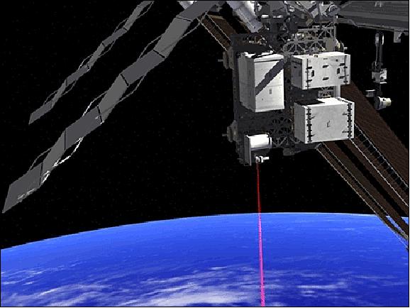
OPALS Operations
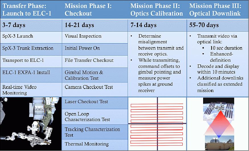
Operational requirements: After OPALS is installed and ready for operation on the ISS, a 90-day mission begins. During these 90 days, OPALS must downlink a video from the ISS to the JPL OCTL (Optical Communications Telescope Laboratory) via an optical communications link. Opportunities for a downlink demonstration occur once every three days on average. One successful downlink of a video file is required to fulfill OPALS technical mission success requirement.
Operational Protocols: OPALS operations begin with the mission operations team identifying when the ISS is predicted to pass within the field of view of the OPALS ground telescope located at the OCTL. Optical communication can only be accomplished through a direct line-of-sight during these times. The mission operations team works with an ISS operations officer to ensure that ongoing on-orbit activities [e.g., robotic, extravehicular activity (EVA) or vehicle maneuvering] do not interfere with this line of sight.
After confirming that OPALS can safely and feasibly operate during a given timeframe, the mission operations team determines the predicted ISS trajectory in the sky over OCTL. A profile of local azimuth and elevation angles is delivered from the mission operations team to the OCTL operator for tracking the ISS pass. The OCTL is then readied to point towards the ISS during this timeframe.
Just prior to a pass occurring, the mission operations team powers up the OPALS Flight System and proceeds with several calibration procedures. The team then uploads pointing products to ensure the Flight System knows where to look for the OCTL. The OCTL's uplink beacon is then turned on, and the Flight System attempts to lock onto and track this uplink beacon for the purpose of downlinking the video file during the pass.
HDEV (High Definition Earth Viewing) Payload
The HDEV experiment places four commercially available HD cameras on the exterior of the space station and uses them to stream live video of Earth for viewing online. The cameras are enclosed in a temperature specific housing and are exposed to the harsh radiation of space. Analysis of the effect of space on the video quality, over the time HDEV is operational, may help engineers decide which cameras are the best types to use on future missions. High school students helped design some of the cameras' components, through the HUNCH (High Schools United with NASA to Create Hardware) program, and student teams operate the experiment. The HDEF payload was developed at NASA/JSC (Johnson Space Center) and funded by TDO (Technology Demonstration Office). 47) 48)
The HDEV investigation places four different commercial high definition cameras external to the ISS on the Columbus External Facility of ESA. The objective is to assess the camera hardware's ability to survive and function in the extreme radioactive environment of LEO (Low Earth Orbit). Educational outreach has been an important component of the HDEV project through the entire projects life cycle. NASA HUNCH program students fabricated some of the HDEV flight components, and most of the HDEV operation will be performed by students teams.
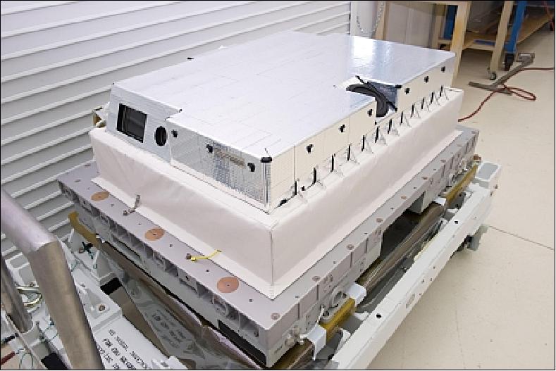
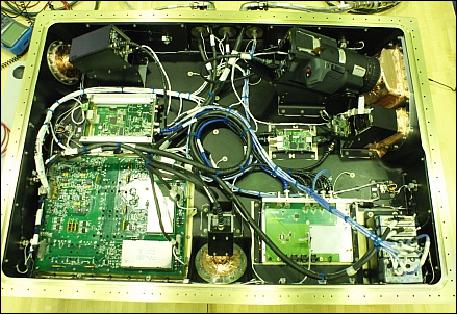
Description: The HDEV primary objective is to validate the space-based performance of the cameras in a variety of operating modes to exercise and demonstrate the features and longevity of the COTS equipment for future ISS Program usage. This payload is an external earth viewing multiple camera system using a set of Commercial-off-the-shelf (COTS) cameras. The HDEV integrated assembly is composed of a camera system of four COTS cameras, integrated Command and Data Handling (C&DH) avionics (Ethernet), and a power data distribution box that allows the integration of the payload's components interface to the ISS Columbus module.
The HDEV visible HD video cameras are a fixed payload camera system that requires no zoom, no pan or tilt mechanisms. The four fixed cameras are positioned to capture imagery of the Earth's surface and its limb as seen from the ISS (i.e., one camera forward pointed into the station's velocity vector, two cameras aft (wake), and the other one camera pointing nadir). The video imagery is encoded into an Ethernet compatible format for transmission to the ground and further distribution. In this format, the video can be viewed from any computer connected to the Internet.
The HDEV does not record video on board the ISS, all video is transmitted to the ground in real-time; any desired recording of the video occurs as ground operations. The COTS cameras, COTS encoder and other electronics are enclosed in a pressurized box to provide a level of protection to the electronics from the space environment. The enclosure contains dry nitrogen at atmospheric pressure, allowing components that are not certified for use in vacuum to be utilized. High quality camera windows are used in the enclosure.
The forward facing camera is a Hitachi GV-HD30, the nadir pointing camera is a Toshiba IK-HR1s and the two aft facing cameras are a Sony FCB-EH4300 and a Panasonic AGHMC150. All cameras have a fixed zoom and do not require any complex commanding.
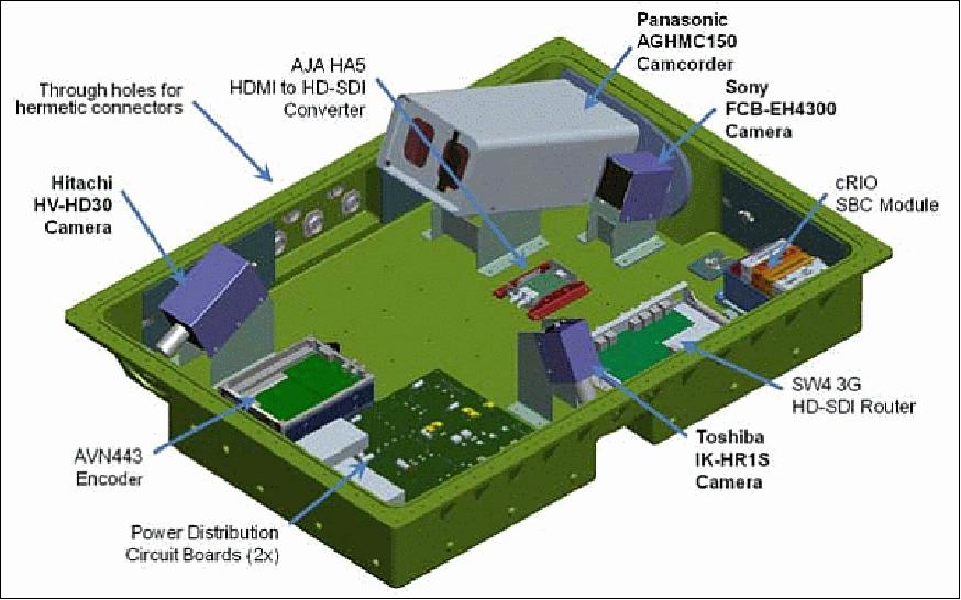
HDEV Design for Operations: The HDEV operates one camera at a time. The HDEV is designed so that when the system is initially powered on, after a 1-2 minute warm up period, the cameras are turned on one at a time in a repeating cycle. The Forward looking camera is powered first, followed by the Nadir and each aft looking camera, such that the HDEV video "follows" a location on the Earth as the ISS passes overhead. This auto-cycle mode of the HDEV does not require any input from ground operators, so the HDEV can be operated any time when the ISS power and data resources are available, without requiring a ground controller present to operate the payload. The only command required, is the initial "power on" command, which is performed by ESA's Columbus Control Center as schedule by ISS Payload Operations.
Alternately as desired by ground controllers, the HDEV video can be commanded. Ground operators have the choice to change the cycle of the images noted in the auto-cycle mode (either changing which cameras that are powered on, or changing the length of time they are powered on), or, if desired, ground controllers can command a single camera to remain powered on and no auto-cycle to take place. — The HDEV is operated from a standard ISS TReK workstation with HDEV specific software installed.
Operations: Camera/system longevity performance — Initially when installed on orbit, the cameras are turned on and video is recorded (on ground) to establish initial camera image quality. Periodically during HDEV operations the camera video images are recorded and compared to previous video. The video image analysis over time will document how well each of the camera systems hold up in the space environment.
Public Relations: The HDEV video is available to the public over the Internet, at the ISS Imagery web site. The HDEV imagery is displayed next to an ISS location map (showing where the ISS is located over the Earth as the video is viewed). The majority of HDEV operations are performed by student teams through the life of the project.
Introduction of Landing Legs for Falcon-9 Launch Vehicles
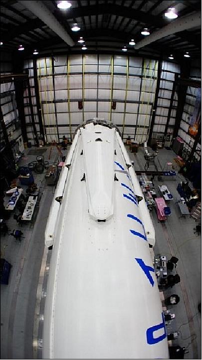
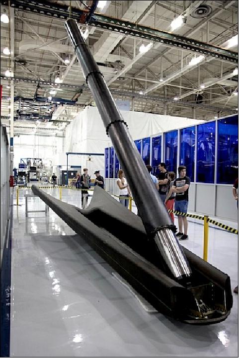
The SpaceX CRS-3 (Cargo Resupply Services-3) flight to the ISS is the first of the Falcon-9 launch vehicle, which will be equipped with a quartet of landing legs in a key test that will one day lead to cheaper, reusable boosters, as announced by Elon Musk, the company's founder and CEO. 49) 50) 51) 52)
The attachment of landing legs to the first stage of SpaceX's new and more powerful, next-generation Falcon-9 rocket counts as a major step towards the firm's eventual goal of building a fully reusable rocket. SpaceX believes a fully and rapidly reusable rocket is the pivotal breakthrough needed to substantially reduce the cost of space access.
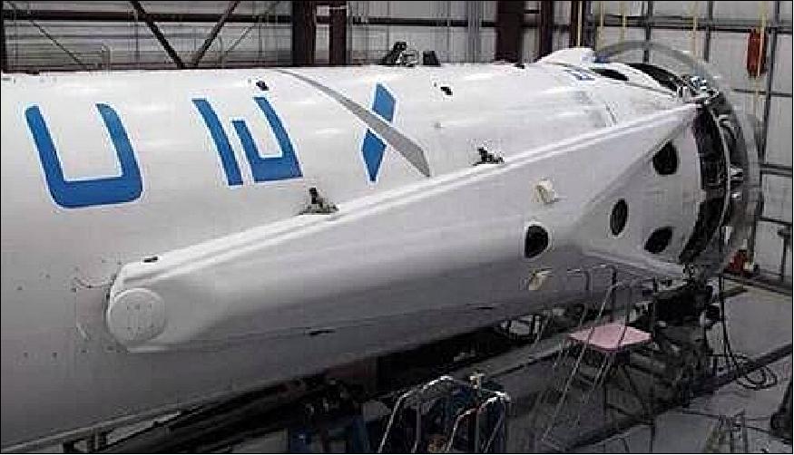
Although this Falcon-9 will be sprouting legs, a controlled soft landing in the Atlantic Ocean guided by SpaceX engineers is still planned for this trip. But SpaceX engineers will continue to develop and refine the technology need to accomplish a successful touchdown by the landing legs on solid ground back at the Cape in Florida. Extensive work and testing remains before a land landing will be attempted by the SpaceX company.
However, F-9 will continue to land in the ocean until SpaceX proves precision control from hypersonic thru subsonic regimes. Ocean recovery teams will retrieve the 1st stage and haul it back to port much like the Space Shuttle's pair of Solid Rocket Boosters.
Rationale for rocket recovery: 53)
Until now, most of the enormous expense of spaceflight has stemmed from the fact that the rockets carrying payloads to orbit have been thrown away after every flight. Each of these discarded launch vehicles costs many tens of millions of dollars, or more, for just one flight. Recovering only the first stage of a Falcon 9 for reuse on multiple flights would allow SpaceX to significantly lower the price of launches for satellites and crewed spacecraft to a level far below what its competitors charge. However, SpaceX estimates that if they are able reach a point where the whole Falcon 9 rocket is recovered and repeatedly reused in such a manner, they may achieve launch costs for around one hundredth of what they currently are.
If they successfully meet this ultimate challenge, then we are on the verge of the first true Space Age, with all of the spaceflights that have occurred before amounting to an expensive, decades-long process of baby steps leading to this new capability. People who make the false claim that NASA's now-defunct Space Shuttle proves reusability offers no economic advantage overlook three points:
1) the huge standing army of NASA and contractor personnel it took to prepare and launch the shuttle resulting in enormous manpower expenditures for that vehicle's budget,
2) the Shuttle was only partially reusable with the giant external propellant tank thrown away after each launch, and
3) the Shuttle was never able to fly frequently enough to significantly lower per-flight costs and achieve a reasonable level of safety. A fully reusable Falcon 9 would not only have a smaller, more agile launch team, but a much faster turnaround between flights as well. A more practiced and seasoned flight and maintenance crew, brought about by the higher flight frequency, will also add an extra measure of efficiency and safety.
To those who would say the above comparison is not reasonable because of the Shuttle's much greater payload capacity, it should be pointed out that eventual reusability is also anticipated for SpaceX's huge new rocket, the FH (Falcon Heavy). The first non-reusable FH flight may occur as early as this year and will have been produced without any government financing of its development. This rocket will be the most powerful since the Saturn V sent astronauts to the Moon. Furthermore, it will have a greater cargo capacity than the Shuttle, much fewer required support personnel and the proposed reusable version is anticipated to have much more rapid turn-around time between flights.
For years, commercial space station manufacturer Bigelow Aerospace has been waiting on the sidelines for economical trips to orbit to enable profitable use of its proposed stations. Industry and friendly governments would then be able to fly people and cargo to and from those stations with much smaller budgets than before. This new industry may supply a massive infusion of growth into the US economy in the coming decades. Driving this growth will be such developments as new medicines in bulk quantities from pharmaceutical companies and specialized manufacturing of novel materials, both of a type that are impossible to produce under Earth's confining gravity or contaminating atmosphere. Other job-creating industries that we cannot even imagine would come into existence as well.
But as great as this accomplishment will be if it succeeds, it is not a good thing that SpaceX is the only major launch provider risking its own assets to aggressively pursue launch vehicle reusability. Such a situation is not healthy for the space launch market. Let's hope that United Launch Alliance and Orbital Sciences Corporation (SpaceX's major American competition) take up the reusability challenge before they face a situation where they literally cannot compete and their business dries up. Failing that, it may be that Blue Origin (coming from the other direction of perfecting reusable suborbital flight before moving on to orbital launch reusability) or some other relatively new upstart will be an ultimate beneficiary of inaction on the part of SpaceX's traditional competitors.
Status of Falcon 9 1st stage recovery test:
• SpaceX engineers had preprogrammed the spent first stage to relight several Merlin 1 D engines after completing the boost phase and stage seperation to stabilize it, reduce its roll rate and then gradually lower its altitude back down to the Atlantic Ocean's surface for a soft landing attempt and later possible recovery by retrieval ships. 55) 56)
- SpaceX CEO and founder Elon Musk reported at a post launch briefing and later tweeted further updates that the Falcon 9 first stage actually made a good water landing despite rough seas, with waves swelling at least six feet.
"Roll rate close to zero (v important!)."
"Data upload from tracking plane shows landing in Atlantic was good! Several boats enroute through heavy seas," Musk tweeted.
Furthermore he reported that the 1st stage survived the ocean touchdown.
"Flight computers continued transmitting for 8 seconds after reaching the water. Stopped when booster went horizontal."
Because of the high waves, the recovery boats had difficulty reaching the booster in the recovery area located some two hundred miles off shore from Cape Canaveral.
References
1) "Optical PAyload for Lasercomm Science (OPALS)," NASA/JPL, URL: http://phaeton.jpl.nasa.gov/external/projects/optical.cfm
2) "Optical PAyload for Lasercomm Science (OPALS)," NASA Fact Sheet, January 09, 2014, URL: http://www.nasa.gov/mission_pages/station/research/experiments/861.html
3) Patrick Blau, "Dragon SpX-3 Cargo Overview," Spaceflight 101, URL: http://www.spaceflight101.com/dragon-spx-3-cargo-overview.html
4) Matthew J. Abrahamson, Oleg V. Sindiy, Bogdan V. Oaida, Santos Fregoso, Jessica N. Bowles-Martinez, Michael Kokorowski, Marcus W. Wilkerson, Alexander L. Konyha, "OPALS: Mission System Operations Architecture for an Optical Communications Demonstration on the ISS," SpaceOps 2014, 13th International Conference on Space Operations, Pasadena, CA, USA, May 5-9, 2014, paper: AIAA-2014-1627, URL: http://arc.aiaa.org/doi/pdf/10.2514/6.2014-1627
5) Abhijit Biswas, Joseph M. Kovalik, Malcolm W. Wright, William T. Roberts, "Optical Communications Telescope Laboratory (OCTL) Support of Space to Ground Link Demonstrations," SpaceOps 2014, 13th International Conference on Space Operations, Pasadena, CA, USA, May 5-9, 2014, paper: AIAA 2014-1710, URL: http://arc.aiaa.org/doi/pdf/10.2514/6.2014-1710
6) B. V. Oaida, M. J. Abrahamson, R. J. Witoff, J. N. B. Martinez, et al., "OPALS: An optical communications technology demonstration from the International Space Station," Proceedings of the IEEE Aerospace Conference, Big Sky, MT, USA, March 2-9, 2013
7) "NASA's OPALS to Beam Data From Space Via Laser," NASA/JPL, July 11, 2013, URL: http://www.jpl.nasa.gov/news/news.php?release=2013-218
8) "NASA Cargo Headed for ISS Aboard Dragon Spacecraft," NASA, April 18, 2014, URL: http://www.nasa.gov/mission_pages/station/structure/launch/index.html#.U1Hj5KKegkA
9) Joshua Buck, Stephanie L. Smith, George Diller, "NASA's OPALS to Beam Data From Space Via Laser," NASA News Release 13-214, July 11, 2013, URL: http://www.nasa.gov/press/2013/july/nasas-opals-to-beam-data-from-space-via-laser/#.Ud-CeazODWI
10) SpaceX Launch to Space Station Reset for March 30, NASA, March 21, 2014, URL: http://www.nasa.gov/mission_pages/station/structure/launch/#.UwS1s87ihqP
11) "NASA Press Kit, March 2014, SpaceX CRS-3 Mission," NASA, URL: http://www.nasa.gov/sites/default/files/files/SpaceXCRS-3_PressKit_FINAL.pdf
12) SpaceX Press Kit, URL: http://www.spacex.com/sites/spacex/files/spacexcrs-3_presskit_final.pdf
13) "SpaceX-3 Manifest Summary," NASA, URL: http://www.nasa.gov/sites/default/files/files/SpaceX3fact_Apr7_508%281%29.pdf
14) Ames' Involvement in the SpaceX-3 Resupply Launch," NASA, April 10, 2014, URL: http://www.nasa.gov/ames/spacex-3/#.U0eHm6KegkB
15) http://www.nasa.gov/sites/default/files/files/SpaceX3cargo_Apr7_508.pdf
16) Linda Herridge, "Veggie Will Expand Fresh Food Production on Space Station," NASA, April 10, 2014, URL: http://www.nasa.gov/mission_pages/station/research/news/veggie/#.U0eGf6KegkA
17) Tony Phyllips, "A new lifeform takes root on the ISS," NASA Science News, April 26, 2014, URL: http://science.nasa.gov/science-news/science-at-nasa/2014/25apr_lettuce/
18) "Micro-7 (SpaceX-3)," NASA, URL: http://www.nasa.gov/ames/research/space-biosciences/micro-7-spacex-3/#.U0ekwKKegkA
19) "T-Cell Activation in Aging (SpaceX-3)," NASA, URL: http://www.nasa.gov/ames/research/space-biosciences/t-cell-activation-in-aging-spacex-3/#.U0eieaKegkA
20) "HEART FLIES (SpaceX-3)," NASA, URL: http://www.nasa.gov/ames/research/space-biosciences/heart-flies-spacex-3/#.U0els6KegkA
21) "Project MERCCURI "Crowdsourced" Space Station Samples Take Flight," NASA, March 12, 2014, URL: http://www.nasa.gov/mission_pages/station/research/news/merccuri/#.U0eoMqKegkA
22) "NASA's Robonaut Legs Headed for International Space Station," NASA, March 12, 2014, URL: http://www.nasa.gov/content/nasas-robonaut-legs-headed-for-international-space-station/#.U0d33aKegkA
23) Chris Bergin, "SpaceX realign Dragon's CRS-3 launch to March 16," NASA Spaceflight.com, Feb. 5, 2014, URL: http://www.nasaspaceflight.com/2014/02/spacex-dragons-crs-3-launch-march-16/
24) "ELaNa V CubeSat Launch on SpaceX-3 Mission," NASA Facts, March 2014, URL: http://www.nasa.gov/sites/default/files/files/ELaNa-V-Factsheet-508.pdf
25) "Falcon 9 CRS-3 Launch 2014," URL: http://cubesat.org/index.php/missions/upcoming-launches/139-crs3-launch-alert
26) Patrick Blau, "Dragon SpX-3 Cargo Overview," Spaceflight 101, URL: http://www.spaceflight101.com/dragon-spx-3-cargo-overview.html
27) Andrea Nunn, "NASA is Laser-focused on Deep Space Communication," NASA, Oct. 6, 2015, URL: http://www.nasa-usa.de/mission_pages/station/research/news/comm_delay_assessment
28) "OPALS Boosts Space-to-Ground Optical Communications Research," NASA/JPL, May 14, 2015, URL: http://www.jpl.nasa.gov/news/news.php?feature=4590
29) Theras Wood, "UrtheCast Teams With NASA To Stream Live High-Definition Earth Video," UrtheCast, April 23, 2015, URL: http://blog.urthecast.com/updates/urthecast-teams-with-nasa-to-stream-live-high-definition-earth-video/
30) Abhijit Biswas, "Demonstration of optical communications from low-Earth orbit," 27 January 2015, SPIE Newsroom, DOI: 10.1117/2.1201501.005758, URL: http://spie.org/x112313.xml
31) Rachel Kraft, Stephanie L. Smith, "NASA Beams 'Hello, World!' Video from Space via Laser," NASA Release 14-159, Junw 6, 2014, URL: http://www.nasa.gov/press/2014/june/nasa-beams-hello-world-video-from-space-via-laser/
32) Elizabeth Howell, "Ground Control To Laser Tom! Space Video Beamed To Earth In 3.5 Seconds," Universe Today, June 9,2014, URL: http://www.universetoday.com/112446/ground-control-to-laser-tom-space-video-beamed-to-earth-in-3-5-seconds/
33) "Station Releases Dragon for Splashdown in Pacific," NASA, May 18, 2014, URL: http://www.nasa.gov/content/station-releases-dragon-for-splashdown-in-pacific/
34) Anna Heiney, "SpaceX-3 Science Payloads Return to Kennedy," NASA, May 23, 2014, URL: http://www.nasa.gov/content/spacex-3-science-payloads-return-to-kennedy/
35) "SpaceX-3 Mission To Return Dragon's Share of Space Station Science," NASA, May 16, 2014, URL: http://www.nasa.gov/mission_pages/station/research/news/spacex3_returns/
36) "NASA ISS On-Orbit Status 12 May 2014," Space Ref, May 12, 2014, URL: http://spaceref.com/international-space-station/nasa-iss-on-orbit-status-12-may-2014.html
37) "NASA ISS On-Orbit Status 7 May 2014," Space Ref, May 8, 2014, URL: http://spaceref.com/international-space-station/nasa-iss-on-orbit-status-7-may-2014.html
38) Ken Kremer, "Dangling Dextre Digs out Docked Dragon Depot prior to Station Departure," Universe Today, May 6, 2014, URL: http://www.universetoday.com/111728/dangling-dextre-digs-out-docked-dragon-depot-prior-to-station-departure/
39) Mike Wall, "NASA Now Streaming Live HD Camera Views of Earth from Space (Video)," Space.com, May 7, 2014, URL: http://www.space.com/25797-nasa-hd-earth-from-space-video-webcasts.html
40) Nancy Akkinson, "HD Livestream of Earth Now Available 24/7 from the Space Station," Universe Today, May 1, 2014, URL: http://www.universetoday.com/111631/hd-livestream-of-earth-now-available-247-from-the-space-station/
41) "ISS HD Earth Viewing Experiment," USTREAM, URL: http://www.ustream.tv/channel/iss-hdev-payload
42) "Crew Prepares for Soyuz and Dragon Departures," NASA, April 29, 2014, URL: http://www.nasa.gov/content/crew-prepares-for-soyuz-and-dragon-departures/index.html#.U2OmAqKegkD
43) "Crew Begins Week with Cargo Transfers, Redocking and Spacewalk Preps," NASA, April 21, 2014, URL: http://www.nasa.gov/content/crew-begins-week-with-cargo-transfers-redocking-and-spacewalk-preps/#.U1YdB6KegkA
44) "Dragon Berthed to Station at 10:06 a.m. EDT," NASA, April 20, 2014, URL: http://www.nasa.gov/mission_pages/station/structure/launch/index.html#.U1YaFKKegkA
45) "Dragon Delivers Science, Station Supplies," NASA, April 20, 2014, URL: http://www.nasa.gov/content/dragon-delivers-science-station-supplies/#.U1Yem6KegkB
46) Ken Kremer, "Easter Sunday Space Station Rendezvous and Berthing for SpaceX Dragon Freighter Successful," Universe Today, April 20, 2014, URL: http://www.universetoday.com/111391/easter-sunday-space-station-rendezvous-and-berthing-for-spacex-dragon-freighter/
47) "High Definition Earth Viewing (HDEV)," NASA News, Feb. 12, 2014, URL: http://www.nasa-usa.de/mission_pages/station/research/experiments/917.html
48) "High Definition Earth Viewing (HDEV)," NASA Fact Sheet, April 3. 2013, URL: http://www.nasa.gov/mission_pages/station/research/experiments/917.html
49) Ken Kremer, "Next SpaceX Falcon 9 Rocket Gets Landing Legs for March Blastoff to Space Station – Says Elon Musk," Universe Today, Feb. 25, 2014, URL: http://www.universetoday.com/109721/next-spacex-falcon-9-rocket-gets-landing-legs-for-march-blastoff-to-space-station-says-elon-musk/
50) http://www.spacex.com/falcon9
51) Patrick Blau, "Falcon 9 v1.1 & F9R Launch Vehicle Overview," Spaceflight101, URL: http://www.spaceflight101.com/falcon-9-v11.html
52) Ken Kremer, "SpaceX Unveils Gorgeous Rocket Legs for Space Station Launch on March 16," Universe Today, March 11,2014, URL: http://www.universetoday.com/110215/spacex-unveils-gorgeous-rocket-legs-for-space-station-launch-on-march-16/
53) Rick D. Boozer, "Rocket reusability: a driver of economic growth," The Space Review, March 10, 2014, URL: http://www.thespacereview.com/article/2466/1
54) Ken Kremer, "SpaceX Resets Space Station Launch with Revolutionary Rocket Legs and Robonaut Legs to March 30," Universe Today, March 22, 2014, URL: http://www.universetoday.com/110326/spacex-resets-space-station-launch-with-revolutionary-rocket-legs-and-robonaut-legs-to-march-30/
55) Ken Kremer, "SpaceX Makes Strides Towards 1st Stage Falcon Rocket Recovery during Space Station Launch," Universe Today, April 19, 2014, URL: http://www.universetoday.com/111377/spacex-makes-strides-towards-1st-stage-falcon-rocket-recovery-during-space-station-launch/
56) Stephen Clark, "SpaceX achieves controlled landing of Falcon 9 first stage," Spaceflight Now, April 19, 2014, URL: http://www.spaceflightnow.com/falcon9/009/140419reusability/#.U1Yx7qKegZM
The information compiled and edited in this article was provided by Herbert J. Kramer from his documentation of: "Observation of the Earth and Its Environment: Survey of Missions and Sensors" (Springer Verlag) as well as many other sources after the publication of the 4th edition in 2002. - Comments and corrections to this article are always welcome for further updates (eoportal@symbios.space).