SBAS (Satellite-Based Augmentation Systems)
Positioning and Navigation
SBAS (Satellite-Based Augmentation Systems) of GNSS
Augmentation of a GNSS (Global Navigation Satellite System) is a method of improving the navigation system's attributes, such as accuracy, reliability, and availability, through the integration of external information into the calculation process. There are many such systems in place and they are generally named or described based on how the GNSS sensor receives the external information. Some systems transmit additional information about sources of error (such as clock drift, ephemeris, or ionospheric delay), others provide direct measurements of how much the signal was off in the past, while a third group provides additional vehicle information to be integrated in the calculation process. 1)
The SBAS (Satellite-Based Augmentation Systems) is a civil aviation safety-critical system that supports wide-area or regional augmentation – even continental scale - through the use of geostationary (GEO) satellites which broadcast the augmentation information. The SBAS function augments primary GNSS constellation(s) by providing GEO ranging, integrity and correction information. While the main goal of SBAS is to provide integrity assurance, it also increases the accuracy with position errors below 1 meter (1 sigma). SBAS is sometimes synonymous with WADGPS (Wide-Area Differential GPS).
The GBAS (Ground-Based Augmentation System) and SBAS that have been implemented or proposed include:
• The Wide Area Augmentation System (WAAS), operated by the United States Federal Aviation Administration (FAA).
• The European Geostationary Navigation Overlay Service (EGNOS), operated by the ESSP (on behalf of EU's GSA).
• The Multi-functional Satellite Augmentation System (MSAS), operated by Japan's MLIT (Ministry of Land, Infrastructure and Transport) Japan Civil Aviation Bureau (JCAB).
• The Quasi-Zenith Satellite System (QZSS), operated by Japan, started initial operations in November 2018.
• The GPS Aided Geo Augmented Navigation (GAGAN) system being operated by India.
• The GLONASS SDCM (System for Differential Correction and Monitoring), operated by Russia with global coverage.
• The CWAAS Canadian WAAS of NavCanada
• The SENEAM WAAS of Mexico
•The BeiDou Satellite Based Augmentation System (BDSBAS) of China
•The Korean Augmentation Satellite System (KASS) of KARI Korea (Aerospace Research Institute)
• The Agency for Aerial Navigation Safety in Africa and Madagascar (ASECNA)
The GBAS (Ground-Based Augmentation System) provides Differential GPS (DGPS) corrections and integrity verification near an airport, replacing ILSs (Instrument Landing Systems). Reference receivers in surveyed positions measure GPS deviations and calculate corrections emitted at 2 Hz through VHF data broadcast (VDB) within 23 nmi (43 km). One GBAS supports up to 48 approaches and covers many runway ends with more installation flexibility than an ILS with localizer and glideslope antennas at each end. A GBAS can provide multiple approaches to reduce wake turbulence and improve resilience, maintaining availability and operations continuity.
Background on the Navigation Signal Delays
Satellite navigation is based on measuring the signal delay between transmission at the satellite and reception by the user receiver. Therefore, the modeling and correction of the additional delay due to the propagation through the atmosphere and mitigation of signal disturbances in the user environment play an important role for the accuracy of the derived position solution. 2)
The positioning with satellite navigation systems like GPS or Galileo is based on time of arrival measurements of the signals transmitted from the satellite at the receiver. The measured signal delays are converted to pseudo ranges by multiplication with the speed of light. The prefix ‘pseudo’ signifies the fact that these ranges do not correspond to the real geometrical distances to the satellites, because the receiver clock is not synchronized to the satellite system time and the measured delays include additional contributions by system and propagation errors which must be corrected for. For synchronization of the receiver clock to the system time measurement data from at least four satellites must be available. Then the receiver clock bias can be solved for as a fourth unknown together with the three unknown co-ordinates of the position x, y, z by triangulation. While system errors can normally not be corrected in real time, propagation errors can be reduced by models or advanced signal processing, where the remaining error depends on the type of measurements e.g. single frequency or dual frequency measurements, signal characteristics e.g. carrier frequency and bandwidth, and the quality of the models used.
Satellite navigation signals are extremely weak when they arrive at the user antenna; the nominal GPS power received at ground is -157 dBW, which is below the noise level. Therefore, the signals are sensitive to shadowing by buildings or vegetation. Navigation signal are spread spectrum signals, which are recovered from noise by dispreading in the receiver, i.e. by correlation with a replica of the satellite code. By this correlation process also the time of arrival, i.e. the delay of the received satellite code is determined. If the direct signal is superposed with reflected signals from the user environment due to multipath propagation, the peak of the correlation function becomes less unique and the accuracy of the delay measurement is reduced.
Table 1 shows an error budget for the GPS standard positioning services with the L1 C/A code. Shown is the UERE (UserEquivalent Range Error), which is the RMS range error that the user must expect in the average worldwide. Note, that these are the residual errors after applying corrections.
In the table the main error contributions besides orbit and satellite clock errors are by propagation effects in the atmosphere and multipath propagation in the user environment. For single frequency measurements in L-band the ionosphere error is even the dominant contributor in the whole error budget. The UERE budget demonstrates the importance of propagation modeling and improvement of correction models for high accuracy navigation, in particular when orbit and clock errors will be reduced by the technological progress in future systems like Galileo and modernized GPS. Therefore, the objective of this paper is to provide an overview about the characteristics of the main propagation effects and common correction and mitigation methods.
Component | Error |
Ephemeris | 2.1 m |
Total (RMS) | 5.3 m |
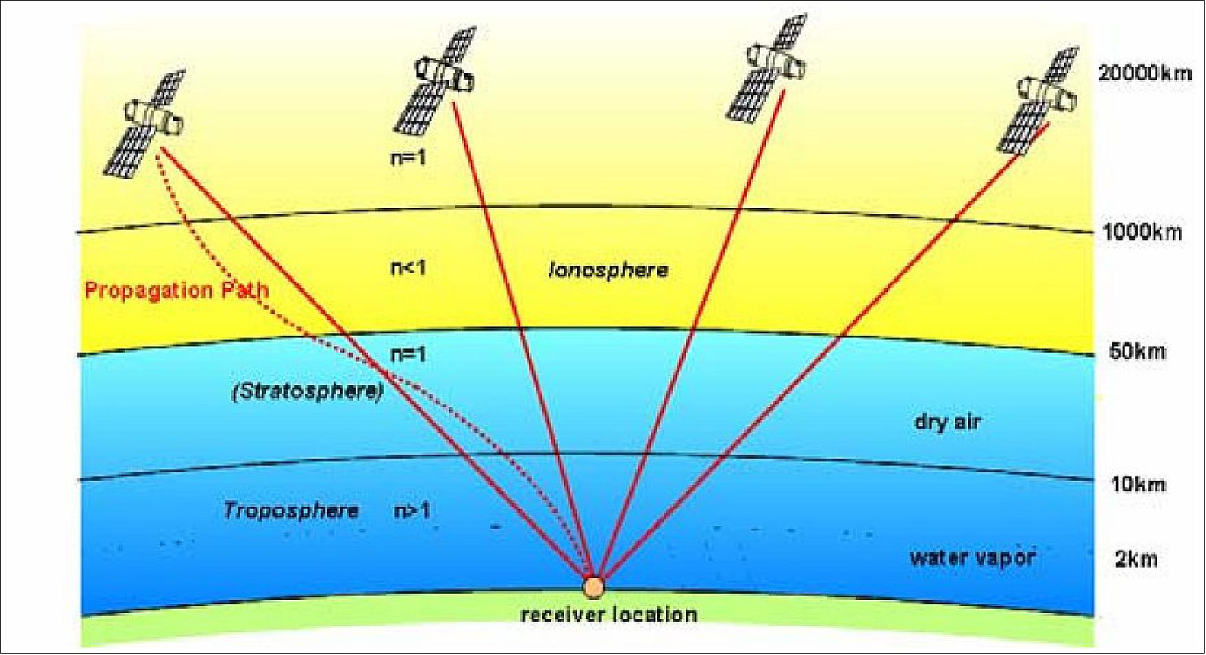
Propagation path through the atmosphere: Figure 1 shows the propagation path of the signals through the different layers of the atmosphere. Within these layers the signal path and the propagation speed is influenced by the variation and gradient of the refractive index. Starting from the top, the signals first reach the ionosphere, where due the existence of free electrons the refractive index is smaller than one. The effect is that the group velocity of the signals is lowered compared to the vacuum but the phase velocity is enhanced. The concentration of free electrons increases with lower altitudes, where the highest concentration is around 300 km above the earth surface, and then decreases again. The corresponding gradient of the refractive index causes a curvature of the propagation path as shown in the figure as dotted line.
Between 50 and 100 km above ground the free electrons disappear and the signals start to propagate through the neutral atmosphere which is composed of different atmospheric gases. With lower altitudes the air pressure and density of the atmospheric gases increase and the refractive index grows accordingly to values larger than 1. The gradient of the refractive index again causes a curvature of the propagation path, which however is in the opposite direction as in the ionosphere. Here both the group velocity and the carrier velocity are slowed down compared to the vacuum speed of light.
The lower part of the neutral atmosphere, the troposphere extends from 0 to about 8 km at the poles, from 0 to about 13 km in mid latitudes and from 0 up to 18 km at the equator. It has the main contribution to the signal delay because it is the densest layer and contains most of the air mass and practically the total amount of water vapor of the atmosphere. Therefore, in the navigation community the delay in the neutral atmosphere is usually just called troposphere delay. The contribution to the signal delay by the water vapor, the so-called wet delay, makes only about 10% of the total troposphere (i.e. neutral atmosphere) delay. However, due to the high temporal and local variability of the water vapor, it is the most crucial component for modeling and error correction. The troposphere is also the region where the daily weather phenomena take place. In the lower troposphere additionally clouds, rain and fog exist. However, their influence on the amplitude and propagation velocity of the signals is negligible in L-band, where current and planned satellite navigation systems operate.
TEC (Total Electron Content) and ionosphere delay: The ionosphere is characterized by ions and free electrons which are created by UV and X-ray radiation of the sun. Therefore, the ionosphere state is coupled to the 11 year cycle of solar activity, to day and night time and to the season. The relevant layer which contains most of these particles extends between 80 and 1000 km above the earth surface. The key parameter for navigation is the TEC, which is the integral of the total electron content in a column of 1m2 from the observation point to the satellite. Table 2 shows typical values of the ionosphere excess path dependent on the carrier frequency for low and high TEC values. The vertical excess path lies normally between these values. The GPS, GLONASS and Galileo frequencies are between 1200 and 1600 MHz.
Frequency | TEC=1016 el/m2 | TEC=1018 el/m2 |
100 MHz | 40 m | 4030 m |
Multipath: Signals which are reflected by the ground, buildings or other obstacles and superpose with the direct signal at the user antenna disturb the correlation function and reduce the ranging accuracy. The error depends on the amplitude, phase and the delay of the echo relative to the line-of-sight signal.
WAAS and EGNOS: One reason for the introduction of the American Wide Area Augmentation System (WAAS) and the European Global Navigation Overlay System (EGNOS) was the reduction of the ionosphere error for single frequency GPS users. These systems derive the ionospheric error in a grid from dual frequency measurements in a regional ground station network and transmit differential corrections and integrity data via geostationary satellites. Because the information is distributed via satellites, these augmentation systems are also called SBAS (Satellite Based Augmentation Systems) in contrast to LAAS (Local Area Augmentation Systems), where local corrections and integrity data are transmitted from ground stations GBAS (Ground Based Augmentation System), e.g. in the vicinity of an airport.
In satellite navigation the modeling and correction of the additional delay due to the propagation through the atmosphere and errors due to further propagation phenomena play an important role for the accuracy of the derived position solution. The largest additional signal delay occurs within the ionosphere. Because the ionosphere delay depends on frequency, it can be precisely determined and nearly completed eliminated by dual frequency measurements. However, for single frequency receivers, like most commercially available mass market GPS-receivers, the ionosphere delay must be corrected by modeling, and a significant error can remain.
The troposphere delay can be separated in a wet component due to water vapor and a dry component due to other atmospheric gases. While the dry delay can be modeled with high accuracy, the wet delay is a crucial component if accuracies in the decimeter or centimeter range are required, because of the high temporal and spatial variability of the water vapor content in the troposphere, although it contributes normally only with 5% to 15% of the total delay.
Since current global navigation satellite systems like GPS, GLONASS and Galileo operate in L-band, attenuation by the atmosphere is negligible. This may change for next generation systems in the future, if additionally higher frequency bands are utilized, e.g. C-Band, which is already allocated for Galileo. However, also in L-band, occasionally, fast amplitude and phase scintillations can occur due to fast variations of the total electron content in the ionosphere or tropospheric turbulences. Strong scintillations occur only rarely, but then they are critical and can even lead to complete loss of the navigation signals by the receiver.
Due to the extreme low signal power of the satellite navigation signals when arriving at the Earth, the signals can be easily attenuated and shadowed by buildings or vegetation, e.g. in urban or rural environments or in indoor applications. In these environments, additionally, multipath propagation by reflections of the signals by the ground, buildings and other obstacles before they arrive at the user antenna can significantly degrade the ranging and positioning accuracy. Multipath propagation is difficult to correct by models, because it depends strongly on the local user environment. Different techniques exist to mitigate the effect of multipath signals as far as possible either by advanced signal processing in receiver or by specially designed antennas, but multipath mitigation is still a hot topic of research.
Status Reports About SBAS Implementations
Augmented Satnav Teams Work Together for Safer Flying
March 2020: All satellite navigation is not created equal. Airliners and other safety-critical classes of users employ ‘augmented’ satnav signals, which possess additional precision plus ongoing reliability guarantees. These signals are generated by regional systems based around the globe. The teams responsible for them met recently at Delhi in India to coordinate their future development. 3)
The 36th Satellite-based Augmentation Systems Interoperability Working Group (SBAS IWG) took place in Delhi last month, hosted by the Airport Authority of India.

For more than 20 years, the IWG has been coordinating the introduction of satellite-based augmentation systems for satnav – today there are 10 either in operation or in active development. For this meeting of the group, SBAS developers and operators were joined for the first time by users of the systems, with representatives of airlines, aircraft makers and avionics manufacturers.
“Satellite-based augmentation systems deliver the necessary accuracy, integrity, availability and service continuity for aircraft to be able to rely on them though all phases of flight, from cruising in the air to being guided down for landing,” notes navigation engineer Didier Flament, head of ESA’s EGNOS and SBAS division, representing ESA at the SBAS IWG.
The US WAAS (Wide Area Augmentation System) and the European EGNOS (European Geostationary Navigation Overlay Service) are leading examples of SBAS (Satellite-based Augmentation Systems). They operate by using additional ground stations to enhance the accuracy and reliability of existing satnav services across given geographic regions.
Signal error measurements and integrity warnings highlighting reliability problems are then relayed to geostationary satellites for rebroadcast to users – messages available to any suitably equipped receiver. The resulting performance enhancements allow satnav to be employed for ‘safety of life’ services, especially aviation, but also any application requiring high precision.
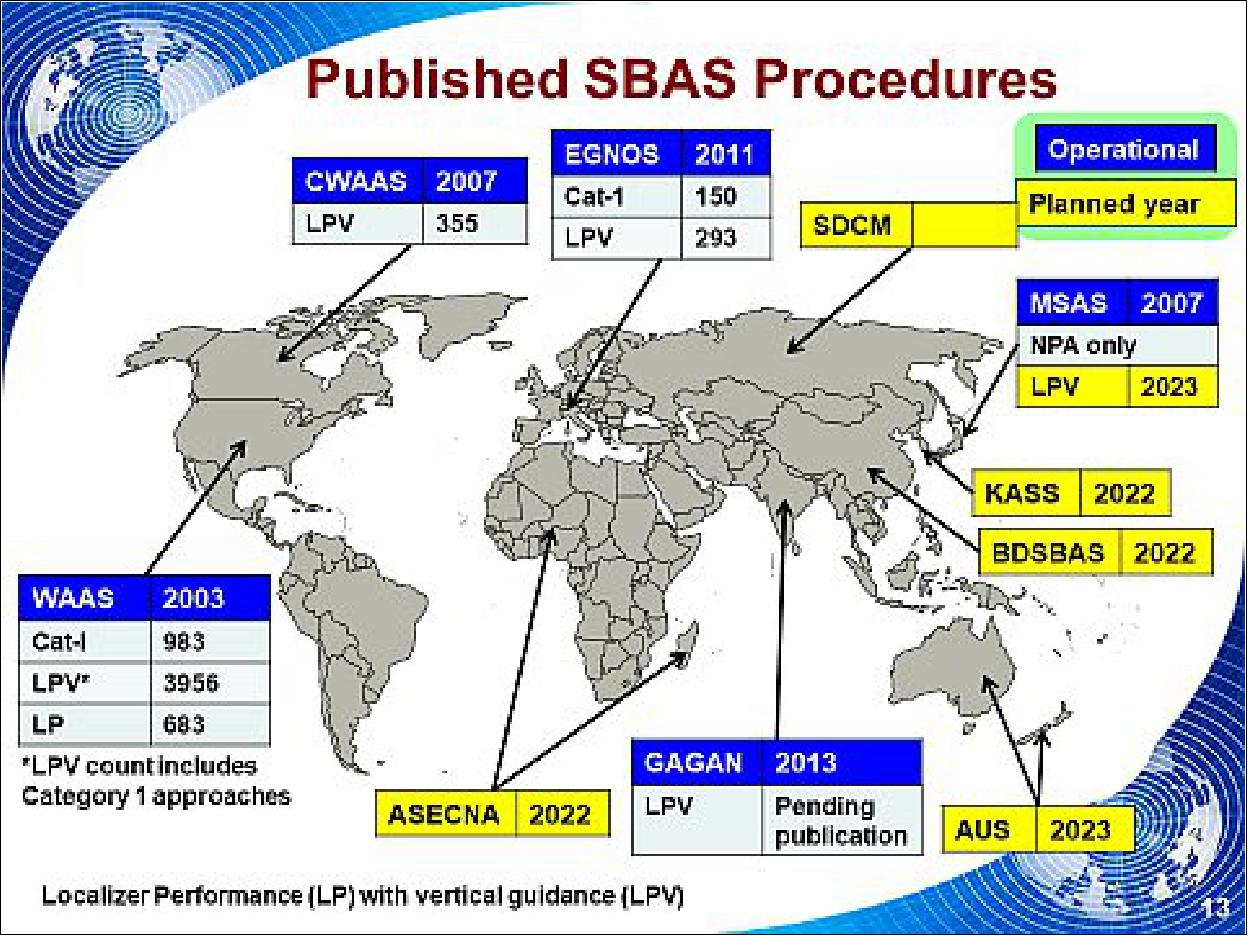
The IWG heard that since their previous gathering six months earlier, a new regional SBAS program has been born : the Southern Positioning Augmentation Network, SPAN, covering Australia and New Zealand, represented at the meeting by Geoscience Australia and Land Information New Zealand.
Also covered at the 50-strong gathering was the progress of the four SBAS currently under definition or development: China’s Beidou SBAS, BDSBAS, represented by the China Satellite Navigation Office; South Korea’s KASS, represented by the Korea Aerospace Research Institute; the African and Indian Ocean SBAS, represented by the Agency for Aerial Navigation Safety in Africa and Madagascar (ASECNA); and the Russian Federation’s System for Differential Corrections and Monitoring (SDCM), represented by Russian Space Systems, RSS.
Current systems are mostly based around the US GPS system (except for SDCM using Russia’s Glonass and BDSBAS using China’s Beidou) but plans are being laid to move to a dual-frequency, multi-constellation version making use of Europe’s Galileo, China’s Beidou and Russia’s Glonass satnav systems later this decade. The corresponding version of Europe’s SBAS will be known as ‘EGNOS v3’.
WAAS (Wide Area Augmentation System)
One of the largest and most important collateral developments in the rise of GNSS (Global Navigation Satellite Systems) is the creation of satellite-based augmentation systems (SBAS). The first of these was the U.S. Wide Area Augmentation System (WAAS). Designed originally to support air navigation in North America, WAAS has also come to be used for a variety of ground- and sea-based operations and inspired in large part the emergence of five other SBAS programs in Europe, Russia, China, India, and Japan. 4)
July 2013: WAAS is a satellite technology that has become essential in making air travel safer and more efficient for both private and commercial travelers. WAAS represents an enormous leap forward in air navigation. When it was first activated on July 10, 2003, WAAS allowed pilots for the first time to rely on the Global Positioning System (GPS) as a primary means of navigation. That means that pilots can use WAAS alone to navigate and land, in most instances. It is important that pilots have as accurate information as possible when landing; WAAS collects, processes, and corrects the GPS information to ensure that the data the pilot receives can be trusted. 5)
Pilots fly into airports with the guidance of either ground-based navigational aids such as Instrument Landing Systems (ILS) or or satellite-based navigation, i.e. GPS. The FAA (Federal Aviation Agency) must develop new approach procedures for an airport before an aircraft can use WAAS. These approach procedures are called Localizer Performance with Vertical guidance (LPV). For the past 60 years, the Category-1 Instrument Landing System (ILS) has been used at airports throughout the National Airspace System to guide aircraft to as low as 200 feet above the runway surface. WAAS now provides similar capability, but at many more runway ends, without airport infrastructure requirements.
The FAA has now published more than 3,100 LPVs based on WAAS at more than 1,500 airports. This is significant because the number of approach procedures based on WAAS has now exceeded twice the number of approach procedures based on its ground-based predecessor, the Category-1 ILS.
The number of WAAS procedures will continue to grow. WAAS has enabled a new Localizer Performance (LP) approach which provides the same lateral accuracy as LPV but without the vertical guidance. The FAA expects to develop 400-500 new LPVs and LPs per year until every qualified runway in the national airspace system has one.
The WAAS signal is provided from space so there is no need for the FAA to install and maintain navigation equipment at an airport, such as that needed for an ILS. Additionally, safety is improved as more aircraft are provided with vertically-guided approaches to more runway ends. This also improves flight planning options.
The way pilots navigate and aviation in general has definitely been transformed.
Background
By virtue of its extensive coverage area, WAAS can provide vertically-guided approach capability at thousands of airports and airstrips where this capability had previously not been available. It is also a core element in transitioning to the satellite-based air traffic control system of the future.
WAAS is designed to improve the accuracy and ensure the integrity of positioning and timing information from GPS satellites.
• GPS alone does not meet FAA’s navigation requirements for accuracy, integrity, and availability for all operations; nor does GPS provide the necessary guarantees that its signal will be accurate, available, and safe to use at all times.
• WAAS corrects for the GPS satellite position errors, ionosphere delays, and other disturbances in the GPS signals, improving the accuracy and reliability of the users’ position solution.
• More importantly, WAAS warns the pilot when the satellites are not functioning correctly and should not be used for navigation.
Although the WAAS was designed for aviation users, it supports a wide variety of non-aviation uses including agriculture, surveying, recreation, and surface transportation–just to name a few. The WAAS signal has been available for non-safety-of-life applications since August 2000, and numerous manufacturers have developed WAAS-enabled GPS receivers for the consumer market. Today, there are millions of non-aviation WAAS-enabled GPS receivers in use.
WAAS was developed for the FAA by Raytheon Corporation.
How WAAS Works
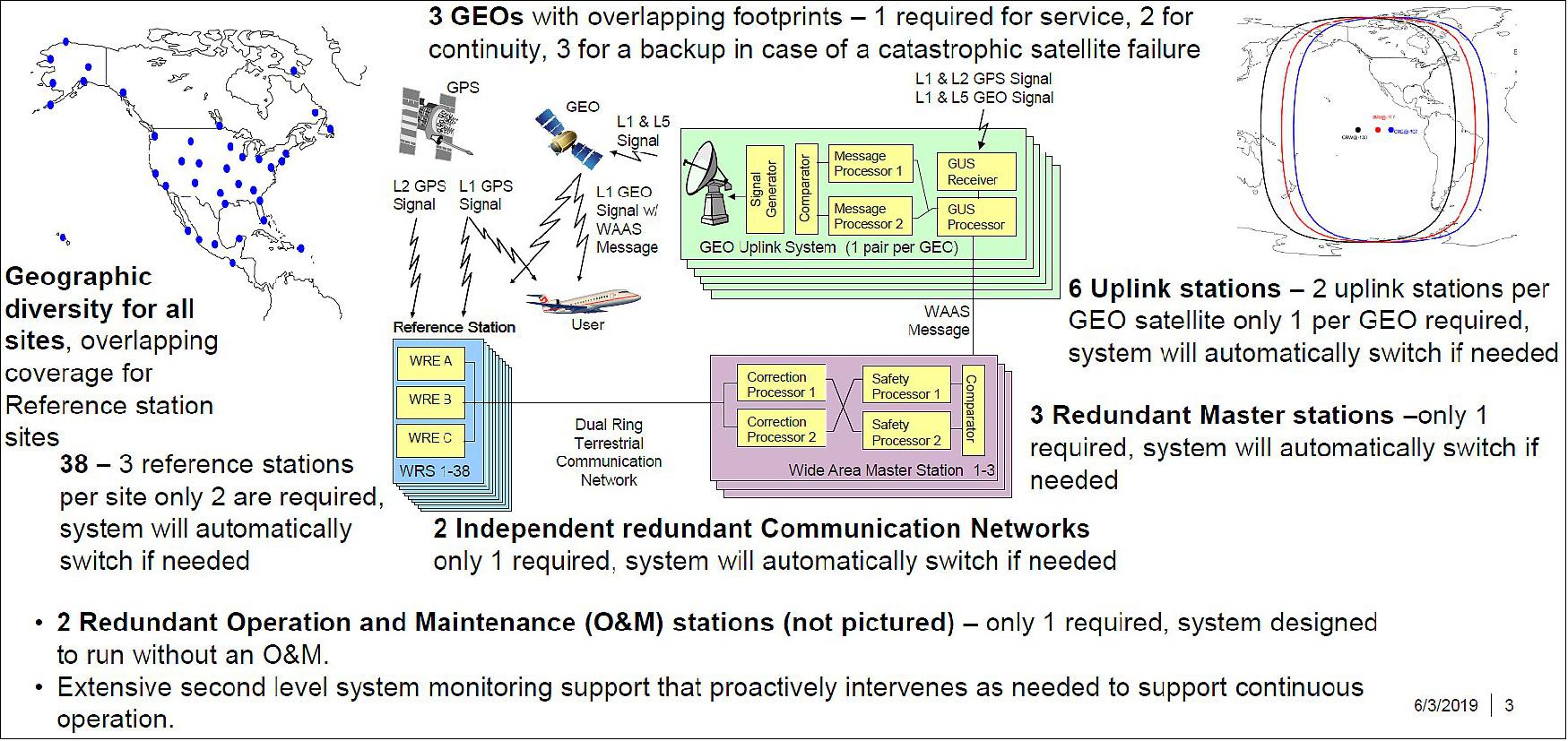
WAAS uses a network of precisely located ground reference stations that monitor GPS satellite signals. These stations are located throughout the continental U.S., Hawaii, Puerto Rico, Alaska, Canada and Mexico. The stations collect and process GPS information and send the information to WAAS master stations. The WAAS master stations develop a WAAS correction message that is sent to user receivers via a ‘GPS-like’ signal from navigation transponders onboard geostationary satellites. The WAAS message improves the accuracy, availability and integrity of GPS-derived position information. Using WAAS, GPS signal accuracy is improved from 20 meters to approximately 1.5 – 2 meters in both the horizontal and vertical dimensions. WAAS hardware consists of: 38 ground reference stations, 3 master stations, 3 geostationary satellites with navigation transponders onboard, 6 uplink stations, 2 operational control centers, and the WAAS terrestrial communications network.
Continuously Operating Reference Stations (CORS)
The U.S. CORS network, managed by the National Oceanic and Atmospheric Administration (NOAA), archives and distributes GPS data for precise positioning tied to the National Spatial Reference System (NSRS). 6)
Over 200 private, public, and academic organizations contribute data from almost 2,000 GPS tracking stations to CORS.
The Online Positioning User Service (OPUS) offers free post-processing of GPS data sets to the centimeter level using CORS information. CORS is also being modernized to support real-time users.
Global Differential GPS (GDGPS)
GDGPS is a high accuracy GPS augmentation system developed by NASA/JPL ( Jet Propulsion Laboratory) to support the real-time positioning, timing, and determination requirements of NASA science missions.
Future NASA plans include using the Tracking and Data Relay Satellite System (TDRSS) to disseminate via satellite a real-time differential correction message. This system is referred to as the TDRSS Augmentation Service Satellites (TASS).
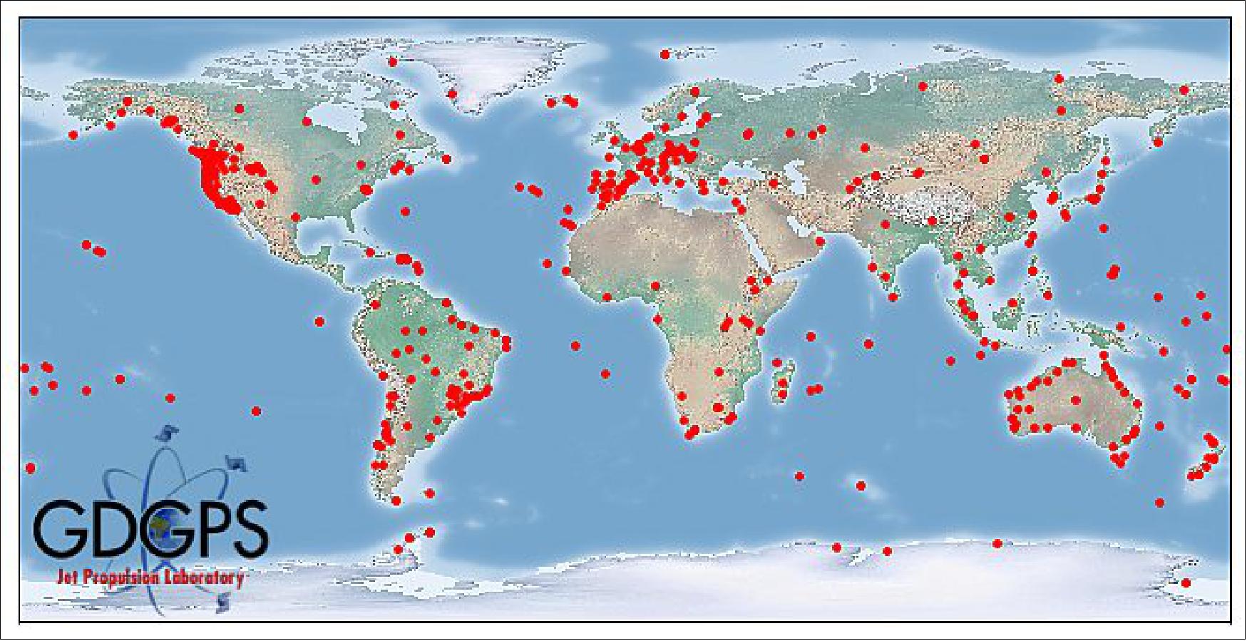
GDGPS Network: The core of the GDGPS tracking network is a JPL-owned and operated network of 75+ geodetic-quality, triple frequency receivers, distributed globally. Additional real-time sites are contributed by a variety of U.S. and international partner organizations. The result is the world's largest real-time GPS tracking network, with more than 200 global sites. All these sites stream their GPS measurements at 1 Hz to the GDGPS Operation Centers (GOCs), where it is processed and analyzed in real-time. 7)
The GDGPS network is highly redundant, by design, to provide a unique measure of reliability to the many critical applications that depend on it, such as real-time GPS integrity monitoring, and precise differential corrections. On average, the network is 25-fold redundant for GPS (meaning that at any given time each GPS satellite is observed, on average, by 25 ground sites), and is minimally 10-fold redundant. The network is 18-fold redundant, on average, for GLONASS.
A variety of communications channels are used for streaming the raw measurements from the tracking sites to the GOCs, including internet, dedicated land lines, and satellite links. When internet is used the data is sent in parallel to multiple GOCs to ensure redundancy of the internet channels. All the GOCs are inter-connected with dedicated high speed land lines.
The GDGPS system is proud to count 4 national timing laboratories among it contributing network partners. In particular, the United States Naval Observatory (USNO) contributes two monitoring sites driven by its Master Clock, allowing the GDGPS System to provide its global users the most accurate real-time realization of USNO UTC. In addition, many GDGPS sites (35+) are driven by atomic frequency standards, enabling robust data quality schemes.
Because we fully own and operate a vast, redundant, global tracking network, we can configure our network receivers to extract any and all GNSS data. These include all L1, L2, and L5 phase and pseudorange measurements, the navigation messages on the various channels, SNR values, and any other publicly available data.
It typically takes about 1 second for the tracking data from most of the monitoring sites to reach the GOCs, and a few more seconds for processing and quality control. The final products, such as the precise corrections to the GNSS broadcast ephemeris, are available within 5 seconds of data collection at the remote site.
To ensure the integrity of the GDGPS products, the data from JPL-owned core of the tracking network can be authenticated. Consequently, the system is immuned to data spoofing. The extremely high redundancy of the network is another powerful measure against spoofing of data from any site or region, as strong majority voting schemes are employed to detect any anomalous sites.
We continue to expand our network, and welcome contributions from interested organizations. We offer our network partners a variety of benefits, including real-time positioning, timing, and environmental monitoring, as well as data archiving and data distribution through the NASA CDDIS facility. Timing laboratories are able to monitor in real-time their frequency standards relative to some of the world's best standards. In some cases we may be able to contribute equipment and expertise toward the installation of a real-time monitoring site.
International GNSS Service (IGS)
IGS is a network of over 350 GPS monitoring stations from 200 contributing organizations in 80 countries. Its mission is to provide the highest quality data and products as the standard for global navigation satellite systems (GNSS) in support of Earth science research, multidisciplinary applications, and education, as well as to facilitate other applications benefiting society.
Benefits
Two of the FAA’s top goals are increased aircraft safety and greater air traffic capacity in a defined airspace. WAAS provides for both, along with additional significant benefits:
• More vertically-guided approach procedures, which are proven to be safer than those without vertical-guidance.
• More flexible approach and departure routings, which will cut arrival times as well as enhance safety and noise abatement.
• More direct, fuel efficient and timely routings through the air traffic control system.
• Augmented navigation source for Automatic Dependent Surveillance-Broadcast (ADS-B). Using WAAS, ADS-B can report a more accurate position to controllers and other aircraft flying in the area than can be provided by GPS alone.
• Navigation source for Terrain Avoidance Warning Systems, which warn pilots and controllers of proximity to the ground.
• Significant government cost savings due to the elimination of maintenance costs associated with older, more expensive ground-based navigation aids.
• Does not require any additional runway infrastructure.
WAAS is a pioneering technology. Currently, no other navigation technologies exist to meet FAA requirements and user needs for the expansion of vertically-guided landing capabilities at thousands of additional airports.
WAAS Milestones
• July 2003 — WAAS is commissioned by the FAA for instrument flight use supporting minimums as low as 250’.
• September 2003 — The first WAAS LPVs are published.
• October 2004 — FAA Administrator Marion C. Blakey announces that U.S. avionics manufacturers are building new WAAS receivers or upgrading existing GPS receivers to WAAS capability and urges aviation users to equip.
• December 2004 – The FAA installs four additional WAAS reference stations in Barrow, Bethel, Fairbanks, and Kotzebue, AK as initial steps in a planned WAAS expansion.
• March 2005 — The FAA finalizes a Geostationary Satellite Communications Control Segment contract with Lockheed Martin for WAAS geostationary satellite leased services through 2016.
• June 2005 — The first international WAAS reference station is installed in Canada.
• March 2006–Due to outstanding system performance, WAAS is approved to support lower minimums, as low as 200’ (feet).
• August 2006 — WAAS service is expanded to cover all of Alaska.
• November 2006 — A new WAAS GEO, the PanAmSat Galaxy XV, is integrated into WAAS, increasing WAAS availability throughout the U.S.
• July 2007 — A second new WAAS GEO, the Telesat ANIK-F1R, is integrated into WAAS, completing the implementation of enhanced WAAS GEO coverage. Later in the same year, the original WAAS Inmarsat GEOs are phased out.
• September 2007 — WAAS service is expanded to cover large portions of Canada and Mexico.
• August 2008– Final Full LPV release integrated into the WAAS, improving service availability to the WAAS and initiating LPV-200 service.
• September 2008– Awarded WAAS Follow-on Contract to the incumbent WAAS contractor to support WAAS technology refresh and to migrate maintenance capability to the FAA’s maintenance organization.
• October 2011 – Third WAAS GEO, the Inmarsat I4F3, is integrated in WAAS providing a ‘3 for 2’ WAAS GEO Satellite constellation which improves computed WAAS availability and continuity of operation.
• September 2012 – Contract is awarded for two new GEOs to replace two operational satellites nearing the end of their 10 year service leases.
• October 2012– WAAS algorithmic and ionospheric modeling improvements fielded to improve WAAS robustness and availability ahead of the upcoming increase in Solar activity.
• May 2013 — The number of runways served by WAAS LPVs exceeds twice the number of runways served by ILS.
• May 2013 — The number of WAAS LPV-capable avionics passes the 90,000 mark and continues to climb steadily each month.
WAAS (Wide Area Augmentation System) Status and Upgrades
• September 22, 2020: The WAAS monitors and evaluates all GPS signals over North America to enable pilots to fly using augmented GPS data for safety of life missions like precision landing and en-route navigation. The system allows pilots to safely land in places that were previously inaccessible because of the airport location and/or weather. It also makes airports without ground-based navigation available to pilots. 9)
Development of Precision Landing with WAAS
- Raytheon Intelligence & Space developed the WAAS system starting in the mid-1990s. From system commissioning in 2003, the RI&S team continued to work with the FAA to implement key enhancements to WAAS as well as training FAA Engineering on WAAS maintenance activities. Starting in 2008, RI&S trained the FAA Engineering team on WAAS maintenance activities. Since 2014, RI&S and the FAA Engineering team have collaborated together to perform many WAAS program modifications and technology upgrades.
WAAS for the Future
- Raytheon and the FAA have introduced many significant changes to WAAS over the 17 years of operational service with no major impact to the user community. System performance has improved over the years in parallel with adding to WAAS LPV and LPV-200 approach procedures catalogue opening up most of the airports in the U.S. for a WAAS-based landing.
- With the next planned WAAS upgrade (called WAAS Phase 4B), the FAA is moving WAAS into a more modern and therefore sustainable processing and network architecture while also adding dual frequency service for those users who equip for the dual frequency capability. Single frequency service will continue to be available for users so all users don’t have to upgrade to dual frequency service in order to continue using WAAS.
- With the addition of dual frequency service anticipated by 2028, WAAS users with dual frequency WAAS-equipped receivers will find that WAAS service will support better positioning determination even during solar storm periods.
• February 4, 2020: Wide Area Augmentation System (WAAS) –Program Overview. 10)
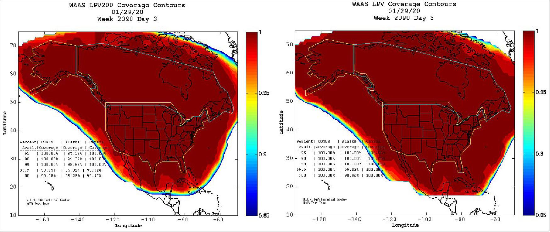
Parameter | CONUS Site/Maximum | CONUS Site/Maximum | Alaska Site/Maximum | Alaska Site/Maximum |
95% Horizontal Accuracy | Arcata,CA | Dallas | Barrow | Bethel |
95% Vertical Accuracy | Arcata | Seattle | Barrow | Cold Bay |
LP Availability | All sites 100% | All sites 100% | All sites 100% | All sites 100% |
LPV Availability | All sites 100% | All sites 100% | Multiple sites 100% | Barrow 99.99% |
LPV200 Availability | Multiple sites 100% | Miami 99.82% | Multiple sites 100% | Barrow 99.35% |
99% HPL | Cleveland 16.434 m | Denver 11.034 m | Cold Bay 20.899 m | Juneau 13.190 m |
99% VPL | Arcata 30.602 m | Billings 19.669 m | Barrow 32.711 m | Anchorage 22.178 m |
Localizer Performance (LP) service is available when the calculated Horizontal Protection Level (HPL) is < 40 m. Localizer Performance with Vertical Guidance (LPV) service is available when the calculated HPL is < 40 m and the Vertical Protection Level (VPL) is < 50 m. Localizer Performance with Vertical Guidance to 200 foot decision height (LPV200) service is available when the calculated HPL is < 40 m and the VPL is < 35 m.
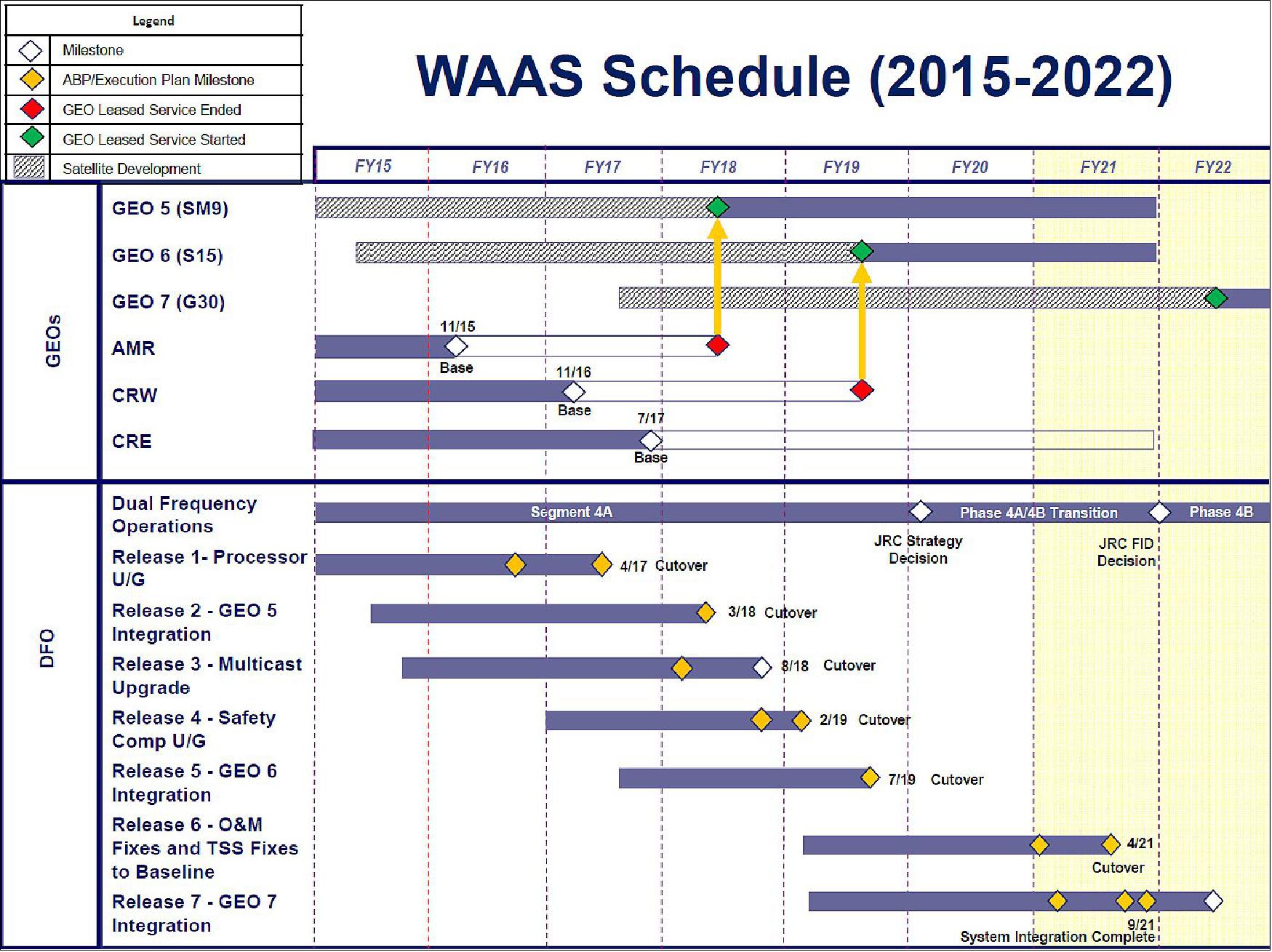
WAAS GEOs
- Anik F1R (CRE): On contract thru July 2020 with options thru July 2022
- Eutelsat 117 WB [ex SatMex 9] (GEO 5): Completed WAAS integration on March 27, 2018
- SES-15 (GEO 6): Completed WAAS integration on June 15, 2019

WAAS Phase 4A – 4B Transition (FY20/21)
- Two year continuation of the WAAS program prior to Phase 4B FID
- Two releases to focused on continued sustainment of the operational WAAS (Releases 6 and 7)
a) Release 6 will improve WAAS performance enhancements by correcting anomalies to the O&M, Test Support Software (TSS) and network critical message logging capabilities
b) Release 7 will integrate GEO 7 into WAAS and upgrade with new Signal Generator including the retrofitting of new
c) SIGGENs at the GEO 5 and GEO 6 legacy GUS sites. GEO 7 projected to be operational by September 2021
- Continued definition of DFO (Dual Frequeny Operations) Phase 4B requirements and alignment with GPS modernization schedule
- Demonstration of alternatives to transition the communications network from Time Division Multiplexing (TDM) to Internet Protocol (IP)
- Additional work will include:
a) Completion of L5 Dual Frequency (DF) signal analysis and support Minimal Operational Performance Standards (MOPS) development to facilitate requirements definition
b) Resolution of WAAS Operations & Maintenance software reliability and maintainability issues
c) Integration of GEO 7
d) Replacement of obsolete Signal Generator (SIGGEN)
e) Generation of WAAS Phase 4B FID Artifacts.
WAAS Dual Frequency Operations (DFO)
WAAS Phase 4 DFO, began in 2014 to leverage improvements the Department of Defense (DoD) will make as part of its GPS modernization program, specifically the introduction of the second civil frequency (L5). Current US Air Force GPS plans predict declaration of GPS L5 Initial Operational Capability (IOC) in FY2022 and Full Operational Capability (FOC) in late FY 2028. FAA plans are for a 24-month transition leading to a WAAS DFO FOC in FY2030.
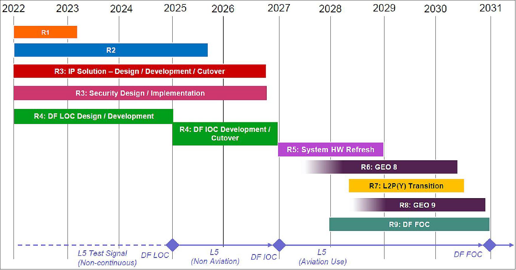
DFO Expected Deliverables
a) DFO development work
b) Re-baseline Dual Frequency (DF) Prototype
c) Develop DF capability from Single Frequency (SF) Code base
d) Separate Correction and Verification (C&Vs) for SF and DF services
e) Develop a shadow environment DF approach
f) Integrate Covariance User Differential Range Error (UDRE) algorithm
g) Modify G-III to track higher GPS PRNs
h) Hardware updates to meet new FAA-E-2892e DF requirement standards
- The WAAS System requires continual modification and updates to meet the safety standards set forth by the FAA. In support of the new DF capability the program office will make updates to the Wide Area Master Stations (WMS) C&V subsystem, Operations and Maintenance (O&M) and the GUS Processor (GPT)
- Further critical DFO work will be identified during the next two years and integrated into the new WAAS DFO Prime Contract projected to be awarded by 2022.
• November 5, 2019: Raytheon has delivered the Wide Area Augmentation System Geosynchronous Earth Orbiting 6 satellite navigation payload to the U.S. Federal Aviation Administration (FAA) to broadcast the WAAS message, which corrects errors in GPS satellite signals, provides expanded coverage, improves accuracy and increases reliability. 11)
- The WAAS GEO 6 payload is now operational and fully integrated into the WAAS network, working with two other WAAS satellite payloads already in orbit.
- The SES-15 satellite hosting Raytheon’s WAAS GEO 6 payload was launched in 2017 and completed extensive system integration in July 2019.
- GEO 6 replaces an older WAAS geostationary satellite that had reached its end-of-service life.
- Operational since 2003, the WAAS network consists of three geostationary satellites and 49 terrestrial-based stations dispersed across the continental U.S., as well as Alaska, Canada, Hawaii, Puerto Rico and Mexico.
• August 16, 2016: Wide Area Augmentation System (WAAS) Update. 12)
Overview
- WAAS provides precise navigation and landing guidance covering the entire National Airspace System (NAS)
- Combination of ground-based and space-based assets
- Augments the Global Positioning System (GPS) Standard Positioning Service (SPS)
- Enables Operators to fly Required Navigation Performance (RNP) 0.1
- Provides both safety and capacity improvements in the NAS and has been operational since 2003
Benefits of WAAS
- Augments GPS: Real-time GPS Corrections and Integrity Information
a) Greater Position Accuracy
b) High Confidence in Computed Position.
- Enhances navigation in all phases of flight
- Enroute, Arrival, and Departure:
a) Provides 100% Availability Of GNSS For Even The Most Critical RNP or RNAV Operations
b) Provides Coverage At All Altitudes Up to 100,000 Feet
c) Provides Navigation Services To Areas Not Served by Any Navigation Aid before WAAS Existed
- Approach:
a) Enhances Safety By Providing Vertical Guidance To Every Runway End In the Coverage Area
b) No Ground Hardware Required At Airport
c) Allows IFR (Instrument Flight Rule) Operations To All Qualified Airports
d) Supports Closely Spaced Parallel Operations (CSPO)
- Enabling technology for NextGen programs
- Automatic Dependent Surveillance Broadcast (ADS-B)
- Performance Based Navigation (PBN)
- Future reductions of ground-based navigation aids
- ILS (Instrument Landing System) rationalization decision closely tied to the implementation and sustainment of WAAS
- 2011 Federal Register Notice (FRN) identified all future Category I approaches to be supported by LPV
- GEO Sustainment (GEOs 5/6/7)
- GEO 5: Successful launch June 2016
- GEO 6: CDR (Critical Design Review) completed February 2016. Expected to be Operational in 2019
- GEO 7: Satellite acquisition. Targeting 2019 for a contract award.
WAAS Now Available in Canada and Mexico
• On 28 September 2007, the WAAS (Wide Area Augmentation System) coverage was expanded into Canada and Mexico. This achievement was made possible by the integration of nine new international wide-area reference stations (WRS) into the WAAS network. In addition to extending WAAS coverage to users throughout large portions of Canada and Mexico, this expansion also benefits the U.S. WAAS users within the U.S., formerly on the fringes of WAAS coverage, are now well within its coverage boundaries. The new WRSs are located in Canada (Goose Bay, Gander, Winnipeg, and Iqaluit) and in Mexico (Mexico City, Puerto Vallarta, Mérida, Tapachula, and San Jose del Cabo). 13)
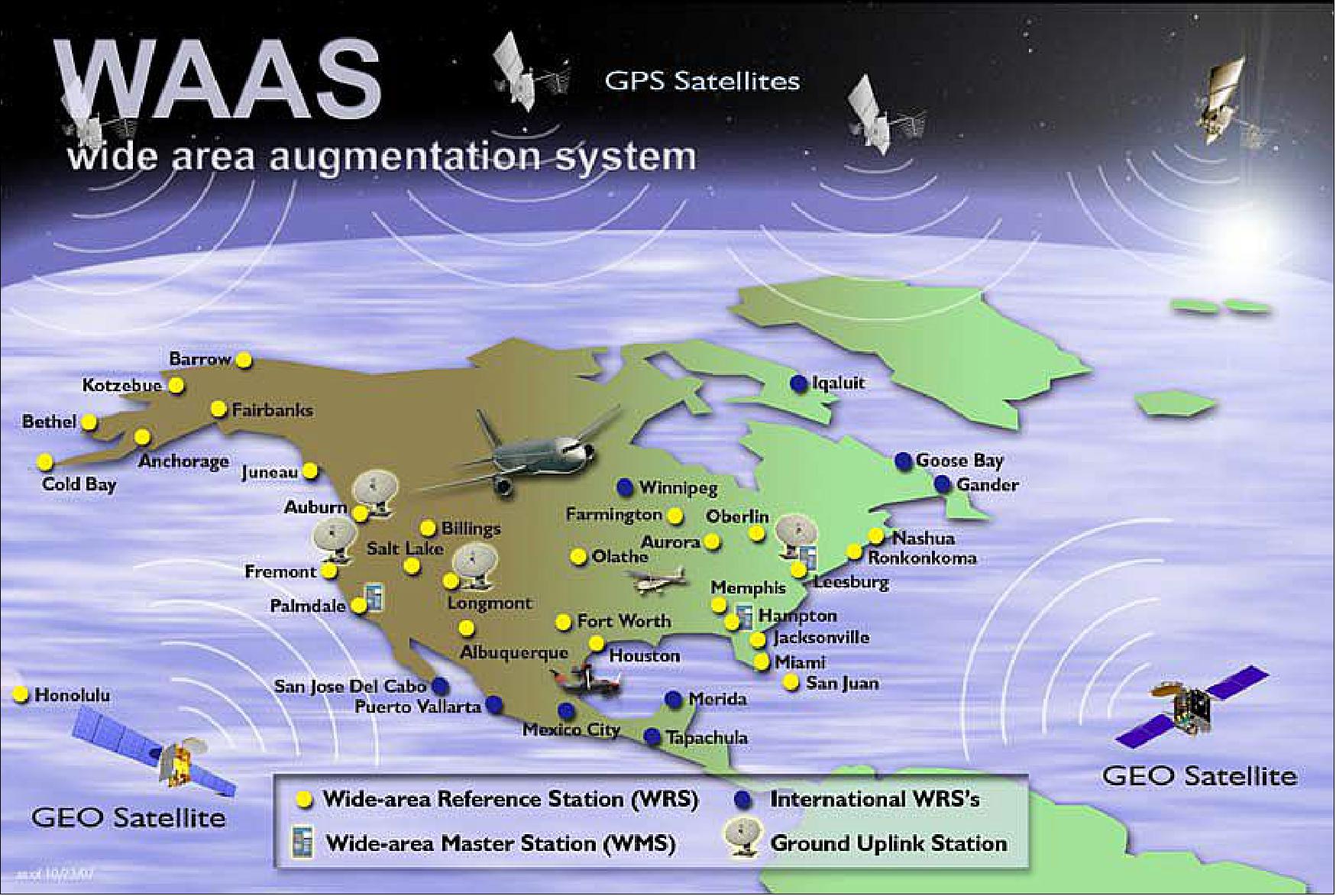
The incorporation of these new WRSs into WAAS meets the FAA Administrator’s Flight Plan goals to bring all nine WAAS international WRSs into operational status by the end of the year, a goal which was met four months ahead of schedule.
For WAAS users, this expansion of service means more locations where vertically-guided approach procedures based upon GPS/WAAS can be developed and used. The FAA has already published over 900 LVP (Localizer Performance with Vertical) approaches throughout the U.S. As such, WAAS equipage has also been steadily increasing. There are currently over 20,000 aircraft equipped to fly LPVs and this number also continues to grow. This latest expansion of WAAS coverage increases the number of locations that can benefit from LPVs, providing even more incentive for users to equip.
This significant milestone for satellite navigation would not have been possible without the commitment and valuable contributions of the Canadian and Mexican aviation authorities who have supported this work at the highest levels under the auspices of the North American Aviation Trilateral Agreement. The result is a highly accurate and reliable navigation service that will benefit all three nations. Although the international WAAS stations are operational, the cooperative work does not end. The FAA has signed supporting agreements with its counterparts in Canada and Mexico documenting a continued commitment to work together to ensure the ongoing operation of this expanded service. For WAAS users in North America, this expansion is the next step on the road of continuous WAAS enhancements. For the world, this is another step in the maturity of the International Civil Aviation Organization’s (ICAO) Global Navigation Satellite System (GNSS) vision.
• July 11, 2007: New WAAS GEO Integrated into System; Coverage Improved
- On July 11th, the WAAS Signal in Space (SIS) broadcast from the Telesat ANIK-F1R geostationary satellite completed integration into WAAS and became usable by WAAS-enabled avionics receivers. The SIS broadcast by Telesat provides higher power and better coverage than the Inmarsat satel-lites initially commissioned with WAAS. The combination of the Intelsat Galaxy XV satellite, integrated in November 2006, with the Telesat satellite provides WAAS users with significantly improved WAAS availability. Further, the orbital location of Telesat extends WAAS coverage into northeastern Canada.
- With the WAAS SIS broadcast successfully deployed on the Telesat and Intelsat GEOs, the initial WAAS GEOs were transitioned out. On July 30, 2007, both the INMARSAT Atlantic Ocean Region – West (AOR-W) satellite (PRN # 122) and INMARSAT Pacific Ocean Region (POR) satellite (PRN #134) were removed from WAAS operation.
- WAAS receivers certified for instrument flight rule (IFR) op-erations are designed so that the addition of the Telesat GEO and the removal of the AOR-W and POR GEOs will be seam-less to the operation of the receiver. The only visible change will be that of the different satellite GPS identification codes noted by the unit; the identifier for the new Telesat ANIK-F1R GEO is PRN #138.
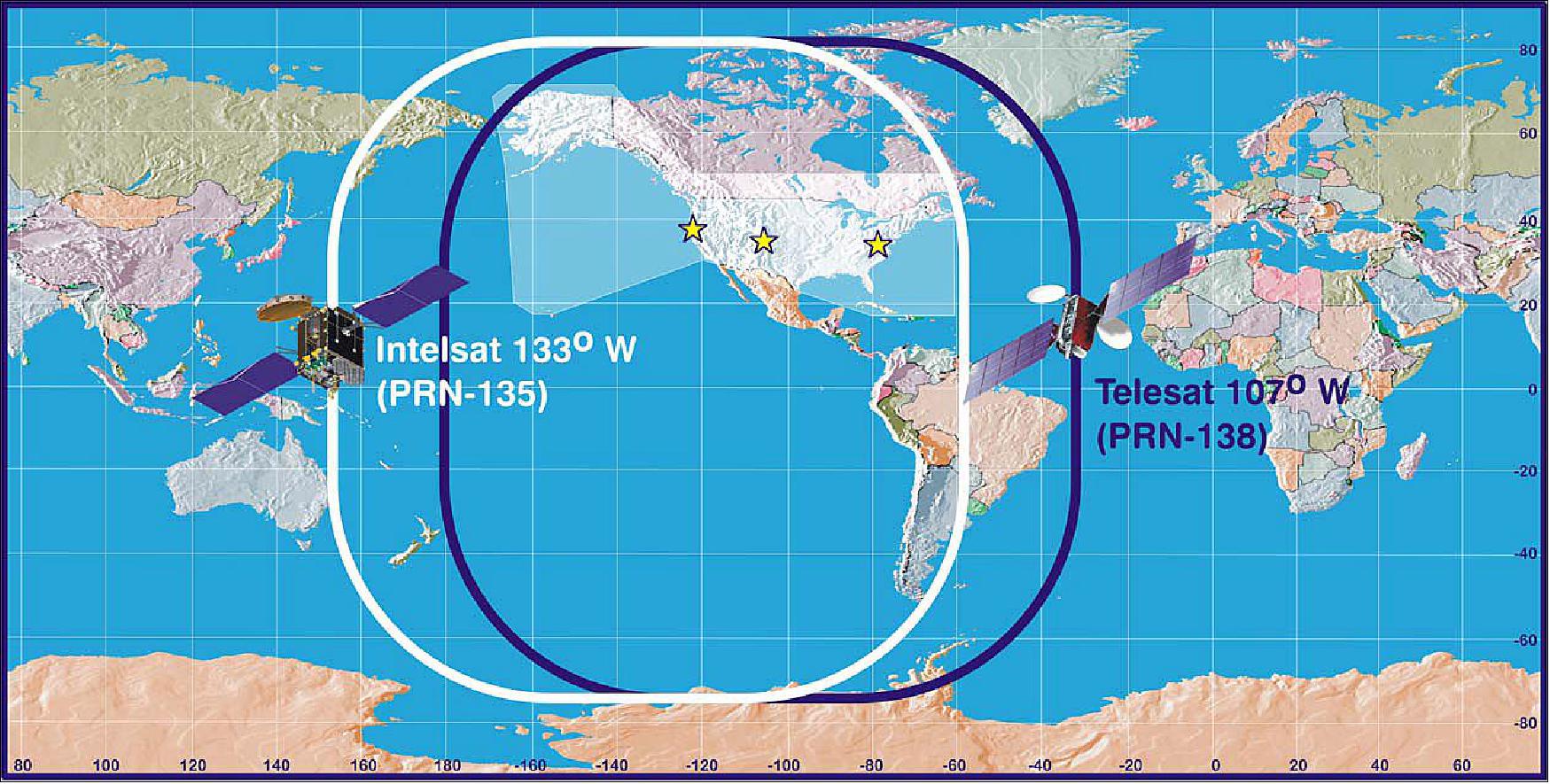
• January 2007: WAAS Agreements Signed with Canada and Mexico
- To prepare for the international expansion of WAAS, implementation agreements were signed between the U.S., Canada, and Mexico. The FAA’s Wide Area Augmentation System (WAAS) program office participated in separate bilateral operational implementation meetings with authorities in Canada (NavCanada) and Mexico (Servicios a la Navegación en el Espacío Aéreo Mexicano, referred to as SENEAM) to refine plans for the implementation of the wide-area reference stations (WRS) in those countries.
- During the meetings, the FAA WAAS program manager and her counterparts in NavCanada and SENEAM signed the international program implementation plans (IPIP). The first of these agreements was signed in December 2006 between the FAA and NavCanada. The second agreement was signed in January 2007 when the FAA met with SENEAM in Mexico. The IPIPs, one for each country, have been jointly developed between the FAA and NavCanada/SENEAM and provide the details of how the higher-level joint agreements to install and implement international WAAS assets will be accomplished. Additionally, the IPIP describes how operation and maintenance of the WRSs will be conducted now that the Canadian and Mexican WRSs have been integrated into the WAAS. The international assets are operated by U.S.-based WAAS operations specialists and maintained by Canadian and Mexican personnel. The international WAAS sites are managed nearly identically to the management of the U.S. assets.
- Training for the initial staff of maintenance technicians for each of these locations was completed prior to the operational date for each of these nine international sites. Requisite resources for were also procured and deployed to the international sites to support the operation and maintenance.
EGNOS (European Geostationary Navigation Overlay Service)
EGNOS is Europe's regional satellite-based augmentation system (SBAS) that is used to improve the performance of GNSSs (Global Navigation Satellite Systems), such as GPS and Galileo. It has been deployed to provide safety of life navigation services to aviation, maritime and land-based users over most of Europe. 14)
EGNOS is owned by European citizens. The European Commission took over ownership of the EGNOS infrastructure from the European Space Agency (ESA) on behalf of the European Union on 1 April 2009. Since 1 January 2014, the exploitation of EGNOS has been fully delegated to the European GNSS Agency (GSA) by the European Commission.
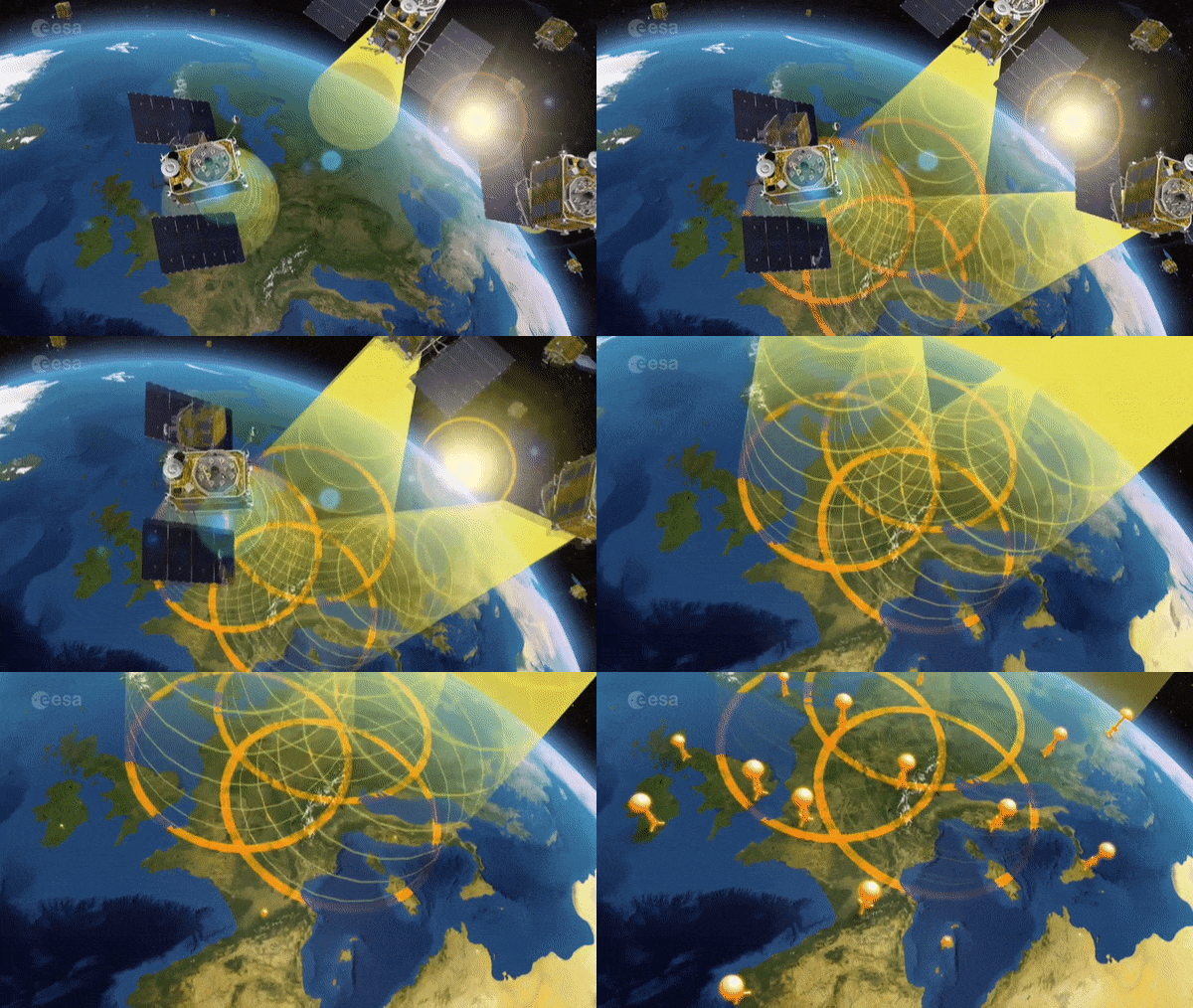
EGNOS uses GNSS measurements taken by accurately located reference stations deployed mainly across Europe and North Africa. All measurements are transferred to a central computing center where differential corrections and integrity messages are calculated. These calculations are then broadcast over the covered area using geostationary satellites that serve as an augmentation, or overlay, to the original GNSS message.
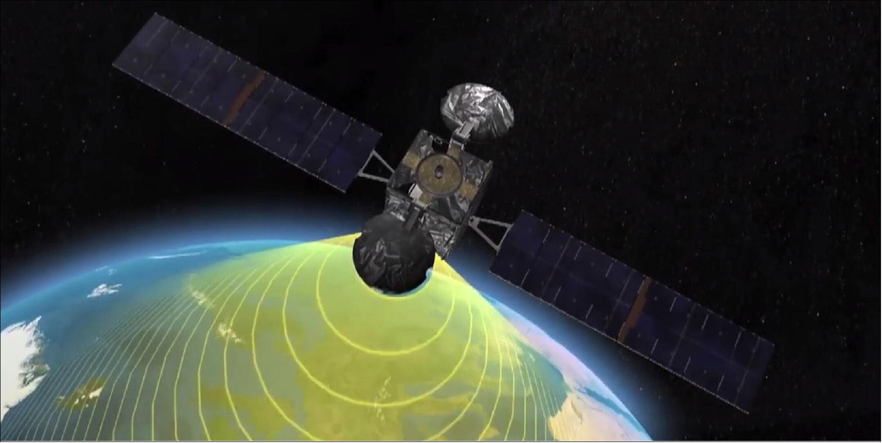
EGNOS augments the GPS L1 (1575.42 MHz) Coarse/ Acquisition (C/A) civilian signal by providing corrections and integrity information for GPS space vehicles (ephemeris, clock errors) and most importantly, information to estimate the ionosphere delays affecting the user. EGNOS messages are broadcast through two geostationary satellites in compliance with applicable standards (MOPS and SARPS). The information provided by EGNOS improves the accuracy and reliability of GNSS positioning information while also providing a crucial integrity message. In addition, EGNOS also transmits an accurate time signal.
As a result, EGNOS improves the accuracy and reliability of GNSS positioning information, while also providing a crucial integrity message regarding the continuity and availability of a signal. In addition, EGNOS also transmits an extremely accurate universal time signal.
Benefiting Numerous Market Segments
EGNOS is essential for applications where accuracy and integrity are critical. For example, in the aviation sector GNSS alone does not satisfy the strict operational requirements set by the International Civil Aviation Organization (ICAO) for use in such critical flight stages as final approaches. However, with the addition of EGNOS, which has been certified for civil aviation since 2011, systems such as GPS can satisfy ICAO standards.
Beyond the aviation sector, EGNOS improves and extends the scope of such GNSS applications as precision farming, on-road vehicle management and navigating ships through narrow channels – to name a few.
Today, EGNOS is benefiting numerous market segments, including aviation, road, rail, maritime, surveying/mapping, location-based services and agriculture.
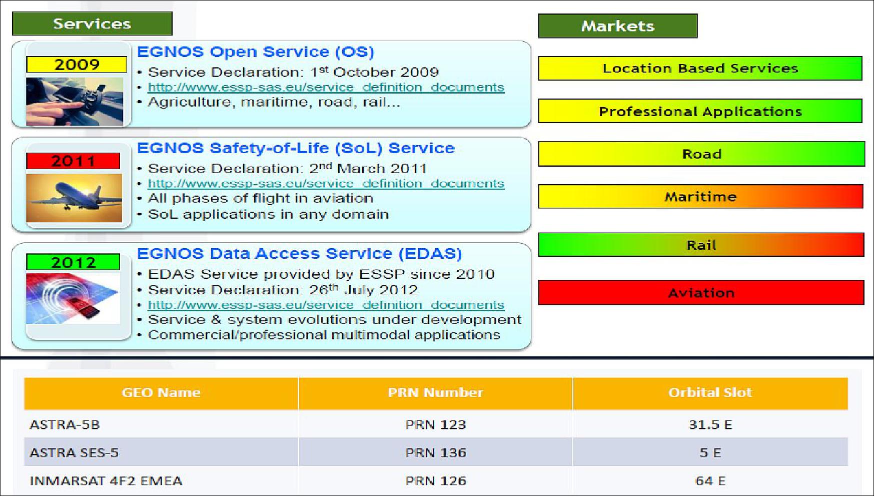
EGNOS Services
EGNOS provides corrections and integrity information to GPS signals over a broad area centered over Europe and it is fully interoperable with other existing SBAS systems. EGNOS provides three services: 15)
1) Open Service (OS): The main objective of the EGNOS OS is to improve the achievable positioning accuracy by correcting various error sources affecting the GPS signals. The corrections transmitted by EGNOS help mitigate the ranging error sources related to satellite clocks, satellite position and ionospheric effects. EGNOS can also detect distortions affecting the signals transmitted by GPS and prevent users from tracking unhealthy or misleading signals. The EGNOS OS is accessible free-of-charge in Europe to any user equipped with an appropriate GPS/SBAS compatible receiver for which no specific receiver certification is required. The EGNOS OS has been available since 1 October 2009.
2) Safety of Life (SoL) Service: This service provides the most stringent level of signal-in-space performance to all Safety of Life user communities. The main objective of the EGNOS SoL service is to support civil aviation operations down to Localizer Performance with Vertical Guidance (LPV) minima. To date, a detailed performance characterization has been conducted only against the requirements expressed by civil aviation. However, the EGNOS SoL service might also be used in a wide range of other application domains (e.g. maritime, rail, road…) in the future. In order to provide the SoL Service, the EGNOS system has been designed so that the EGNOS Signal-In-Space (SIS) is compliant with the ICAO SARPs for SBAS. The EGNOS SoL Service has been available since 2 March 2011.
3) EGNOS Data Access Service (EDAS): This service is aimed at users who require enhanced performance for commercial and professional use. EDAS is the EGNOS terrestrial data service and offers ground-based access to EGNOS data in real time and also in a historical FTP archive to authorized users (e.g. added-value application providers). EDAS is the single point of access for the data collected and generated by the EGNOS ground infrastructure distributed over Europe and North Africa. Application providers can connect to the EGNOS Data Server and use EGNOS products to offer high-precision services to their customers. The EGNOS EDAS has been available since 26 July 2012.
The IWG (Interoperability Working Group) is working to ensure that the future evolutions of all these systems will operate on a similar basis with common technical requirements, allowing the easy transition of continent-crossing air traffic from one system to another. This will be especially important in regions where system coverage overlaps.
The gathering also included an exchange of information on SBAS research and development, including applying SBAS to Europe’s railways.
EGNOS Architecture
EGNOS is divided into four functional segments:
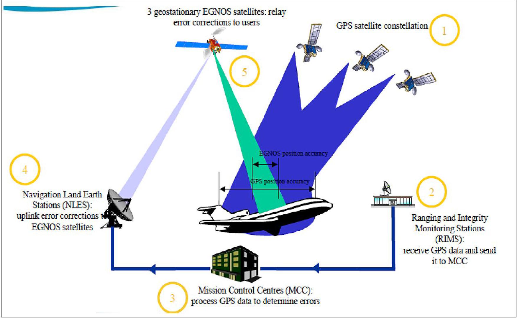
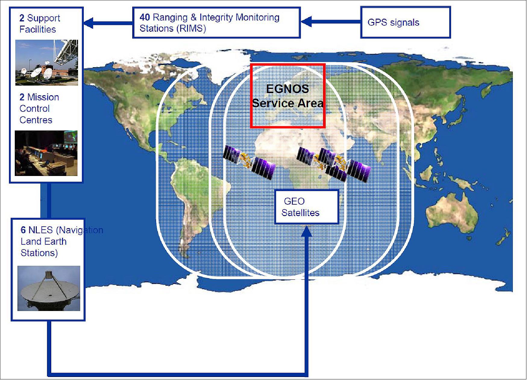
1) Ground segment: comprises a network of 40 Ranging Integrity Monitoring Stations (RIMS), 2 Mission Control Centers (MCC), 2 Navigation Land Earth Stations (NLES) per GEO, and the EGNOS Wide Area Network (EWAN), which provides the communication network for all the components of the ground segment.
• 40 RIMS: the main function of the RIMS is to collect measurements from GPS satellites and to transmit these raw data every second to the Central Processing Facilities (CPF) of each MCC. The configuration used for the initial EGNOS OS includes 40 RIMS sites located over a wide geographical area.
• 2 MCC (control and processing centers): these receive the information from the RIMS and generate correction messages to improve satellite signal accuracy and information messages on the status of the satellites (integrity). The MCC act as the EGNOS system’s 'brain'.
• 2 NLES per GEO: the NLES transmit the EGNOS message received from the central processing facility to the GEO satellites for broadcasting to users and to ensure synchronization with the GPS signal.
2) Support segment: In addition to the above-mentioned stations/centers, the system has other ground support installations involved in system operations planning and performance assessment, namely the Performance Assessment and Checkout Facility (PACF) and the Application Specific Qualification Facility (ASQF) which are operated by the EGNOS Service Provider (ESSP).
• PACF (Performance Assessment and Check-out Facility): provides support to EGNOS management in the form of performance analysis, troubleshooting, and operational procedures as well upgrading specifications and validations and providing maintenance support.
• ASQF (Application Specific Qualification Facility): provides civil aviation and aeronautical certification authorities with the tools to qualify, validate and certify the different EGNOS applications.
3) Space Segment: composed of at least three geostationary satellites broadcasting corrections and integrity information for GPS satellites in the L1 frequency band (1575.42 MHz). This space segment configuration provides a high level of redundancy over the whole service area in the event of a failure in the geostationary satellite link. EGNOS operations are handled in such a way that, at any point in time, at least two GEOs broadcast an operational signal.
4) User Segment: the EGNOS user segment is comprised of EGNOS receivers that enable their users to accurately compute their positions with integrity. To receive EGNOS signals, the end user must use an EGNOS-compatible receiver. Currently, EGNOS compatible receivers are available for such market segments as agriculture, aviation, maritime, rail, mapping/surveying, road and location based services (LBS).
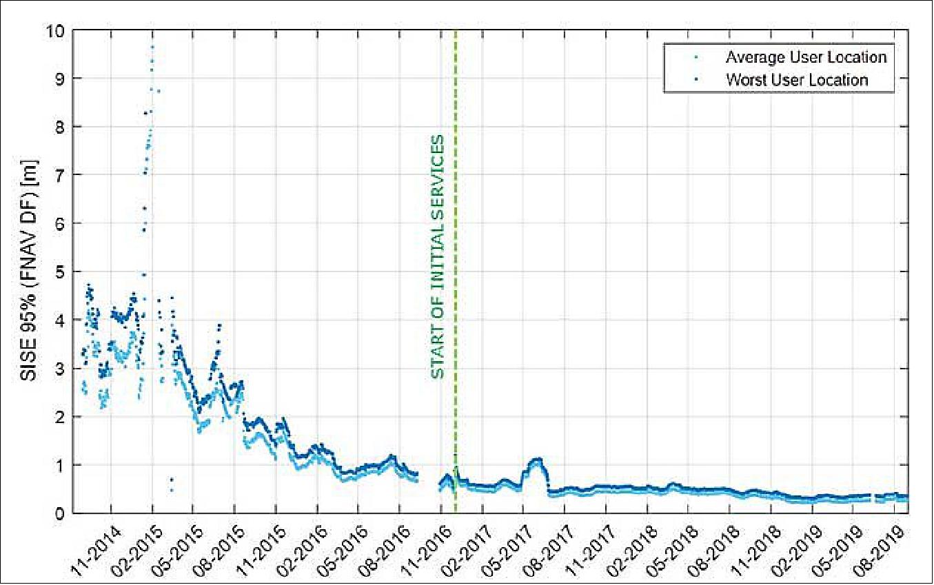
Galileo’s signal-in-space quality has steadily improved over the past few years, reaching in 2019 a best signal-in-space error (SISE) of about 0.25 meters (95%, global average; Figure 19). This has been achieved through a combination of several factors, including the increased number of operational satellites, enhanced versions of the Ground Mission Segment, and higher uplink rate of the navigation message (lower age of data). This performance is well within Galileo’s initial service accuracy commitments, as defined in the public Open Service – Service Definition Document (OS SDD). 18)
EGNOS Status and Upgrades
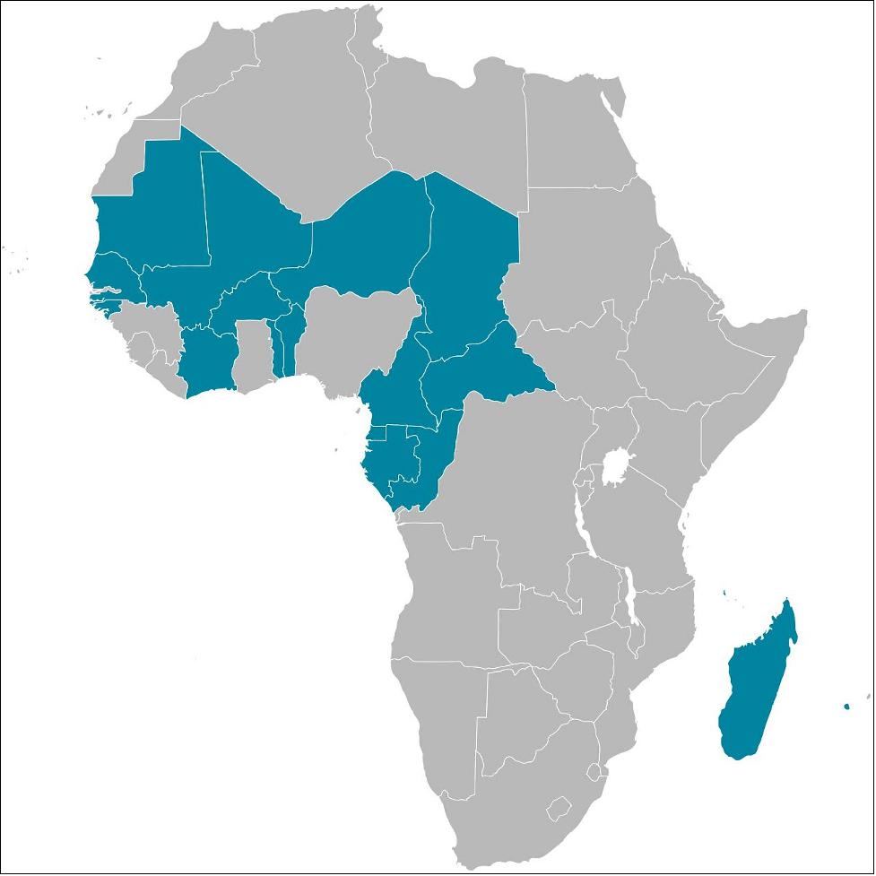
• June 29, 2022: European technology that allows satellite navigation signals to safely guide aircraft down for landing in the majority of Europe’s airports will now be put to use across Africa and the Indian Ocean. ASECNA, the Agency for Air Navigation Safety in Africa and Madagascar, and ESA today signed an agreement to deploy a Satellite-based Augmentation System (SBAS) across a service region of more than 16.5 million km2, one and a half times the size of Europe’s coverage area. 19)
- ESA will provide technical support to ASECNA based on Europe’s EGNOS technology and using the Galileo satellites. The system initial operational capabilities are projected to enter into service from 2025.

- ESA Director General Josef Aschbacher comments: “I welcome this exciting new partnership with Africa. International cooperation has always been an ESA priority; space technology has the potential to improve everyone’s lives, and by working together we get to make that happen. EGNOS technology – designed, developed and demonstrated in Europe – will have its clear safety, environmental and economic benefits extended to African airports, airlines and passengers.”
- ASECNA Director General Mohamed Moussa remarks: “The implementation of satellite-based augmentation infrastructure will represent a huge step forward towards the unification of the African airspace. Airspace users will benefit across the continent from the most advanced navigation services and will significantly improve the safety and efficiency of their operations, and reduce their environmental impact. This service sufficiently accurate and reliable to guide aircraft for critical flight operations will also be valuable across many other important sectors, such as land and maritime transport, precision agriculture, drone navigation, mapping and surveying.”
- ASECNA Chairman of the Board Jean Lamy added: “This program is part of the Africa-EU strategic partnership on satellite navigation. It provides a solution for the implementation of the navigation and positioning component of the Space Policy of the African Union. It will support the development of a continuum airspace purpose of the single Sky for Africa Project (CUPA Project) developed by ASECNA and which contribute to the African Union’s Single Air Transport Market initiative (SAATM)”.
- ESA Director of Navigation Javier Benedicto adds: “Together with Galileo, EGNOS is Europe’s other satellite navigation system, which is today in routine use at around 367 European airports and helipads. Through the use of EGNOS, satellite navigation signals become sufficiently accurate and reliable for all kinds of ‘safety-of-life’ uses. ESA, as the original designer of the EGNOS system, is well-placed to advise on the design and establishment of a new augmentation system with our ASECNA partner.”
- Didier Flament, overseeing EGNOS for ESA, adds: “Building on past knowhow, this new system will deliver positioning with metre-level accuracy and with a high level of Integrity with a progressive coverage of the continent.”
- Louis Bakienon, Director of the ASECNA SBAS Programme, adds “SBAS services will enhance navigation operations for all phases of flight, from en-route down to precision approaches, and surveillance operations as well, as providing a source of position for terminal and surface surveillance.”
- Julien Lapie, Manager of the ASECNA SBAS programme adds : “The ASECNA SBAS programme primarily aims to provide, through a self-sufficient infrastructure, airspace users with advanced navigation services to enhance significantly flight safety and efficiency, reduce their environmental impacts and improve airport accessibility. This programme is a key enabler to the implementation of the Space Policy and Strategy of the Africa Union, and is recognised by the International Civil Aviation Organisation.”
- ASECNA provides air navigation services within an airspace of 16.5 million sq. km, divided into six flight information regions covering its Member States Benin, Burkina Faso, Cameroon, Central African Republic, Comoros, Congo, Côte d’Ivoire, France, Gabon, Guinea Bissau, Equatorial Guinea, Madagascar, Mali, Mauritania, Niger, Senegal, Chad and Togo.
- EGNOS, the European Geostationary Navigation Overlay Service sharpens the accuracy of GPS signals over European territory up to metre-scale precision while also giving a real-time‘integrity’ – or reliability – level of the signals and of the final corrected position thanks to EGNOS. The current EGNOS system relies only on US GPS signals but an updated version is being prepared for implementation later this decade (by 2028) – EGNOS v3 – which will also utilise Galileo signals, further increasing its accuracy and robustness. Moreover, this second generation will also provide an increased level of resilience to security (in particular cyber security) threats.
- The current EGNOS allows aircraft to be guided safely down in any visibility to within 60 metres of height from the runway while the new EGNOS V3 aims at delivering a future capability of an auto-landing service (a first feasibility demonstration of this capability was performed in November 2019 with an Airbus A350 at Toulouse Airport).
- The Satellite-based Augmentation system of ASECNA will provide the same levels of services, based on an fully-fledged African infrastructure, composed of a ground segment (reference stations, mission control centres, uplink stations) and a space segment.
- ASECNA signed an international agreement with the European Union in 2018 on satellite navigation, and is benefiting from funding and access to the EGNOS technology. ESA will deploy a team of around ten experts, providing technical support focused on ground infrastructure for the SBAS while French space agency CNES will advise on engineering of the demonstrator, the space segment and performance.
• March 17, 2021: With 26 satellites in orbit and more than two billion receivers in use, Europe’s Galileo satellite navigation system has made a massive impact. But our continent has another satnav system that has been providing safety-of-life services for ten years now – chances are that you’ve benefited from it without noticing. 20)
- Its name is EGNOS, the European Geostationary Navigation Overlay Service. Transmitting signals from a duo of satellite transponders in geostationary orbit, EGNOS gives additional precision to US GPS signals – delivering an average precision of 1.5 meters over European territory, a tenfold improvement over un-augmented signals in the worst-case – and also confirmation of their ‘integrity’ – or reliability – through additional messaging identifying any residual errors.

- While its Open Service has been in general operation since 2009, EGNOS began its EU-guaranteed safety-of-life service in March 2011.
- ESA designed EGNOS as the European equivalent of the US WAAS, Wide Area Augmentation System, working closely with the European air traffic management agency Eurocontrol, passing it to the European GNSS Agency, GSA, to run operationally.

Guiding Airliners Down
- First and foremost its primary customer is aircraft. Imagine an airliner coming into land at Charles de Gaulle, or another major European airport, in bad weather. The pilots cannot see their runway through clouds and rain, but without needing any guidance from the ground they can still confidently descend all the way down to just 60 meters’ altitude before needing to make visual contact with the tarmac – thanks to EGNOS.
- France’s Pau Pyrénées Airport was the first airport to utilize EGNOS, on 17 March 2011. Today, more than 385 airports and helipads and 60 airlines across Europe are today utilizing such EGNOS-based LPV-200 approaches, short for ‘Localizer Performance with Vertical guidance – 200 ft (60 m)’. The freely-available EGNOS service requires no ground equipment whatsoever, replacing the radio guidance beamed upward by traditional CAT I Instrument Landing System (ILS) infrastructure with no decrease in performance.
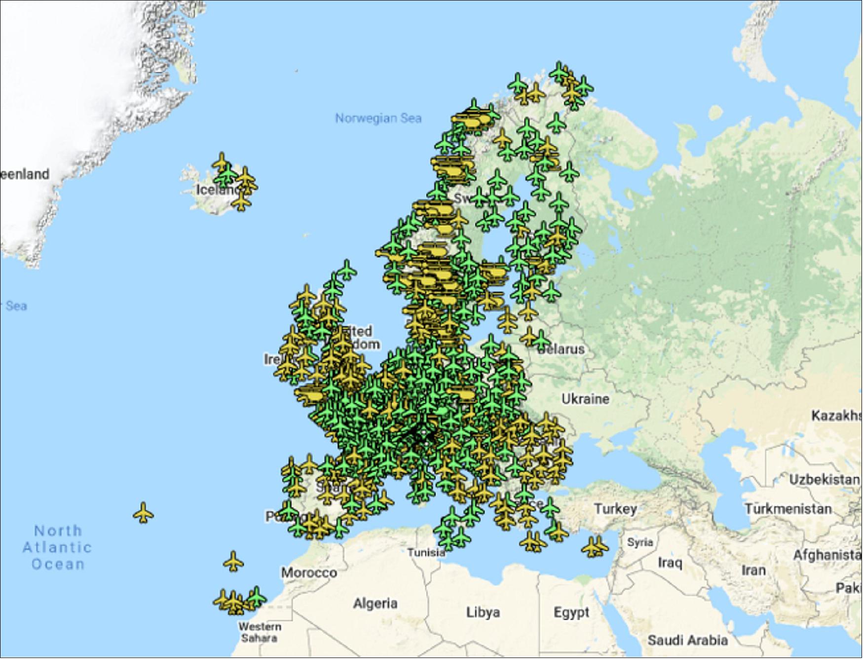
EGNOS Serving Drones
- Having guided hundreds of thousands of passengers down safely during the past decade – and employed widely in additional sectors such as maritime navigation – EGNOS is now being eyed as the enabler of smaller aerial vehicles making safe use of airspace, in the shape of autonomous drones.
- The GSA has supported numerous trials of ‘remotely piloted aircraft systems’ equipped with EGNOS as well as Galileo through its EGNSS4RPAS project. The projection is that crewed aircraft will be vastly outnumbered in our skies by all kinds of automated aerial vehicles, employed for everything from weather and environmental monitoring to personalized delivery services.

- The traditional person-based traditional air traffic control model will need to evolve to accommodate such a shift, based on automated monitoring, traffic management and collision avoidance. This highly automated version of air traffic control is termed ‘U-space’.
- EGNOS’s safety-of-life service is seen as essential to making this happen, moving from today’s situation where drones are limited to specific air corridors and line-of-sight operations to let them roam freely but safely in busy airspace and built-up areas.
- “The whole idea behind EGNOS’s safety-of-life has been to render satellite navigation sufficiently reliable for any kind of use,” explains Didier Flament, leading ESA’s EGNOS team. “After ten years of faultless operations, new applications are becoming plain: drone flight is one example, and EGNOS is also being evaluated for train positioning as well as assisted and autonomous automobile driving.”
New Generation of Service
- ESA retains responsibility for the system’s future evolution, and the middle of this decade should see the debut of its new generation, known as ‘EGNOS v3’.
- Didier adds: “While the current system only works with single-frequency GPS signals, EGNOS v3 will operate on a multi-frequency, multi-constellation basis, able to augment all available satellite signals in both L1 and L5 bands, including Galileo. The result will be far enhanced performance and reliability.
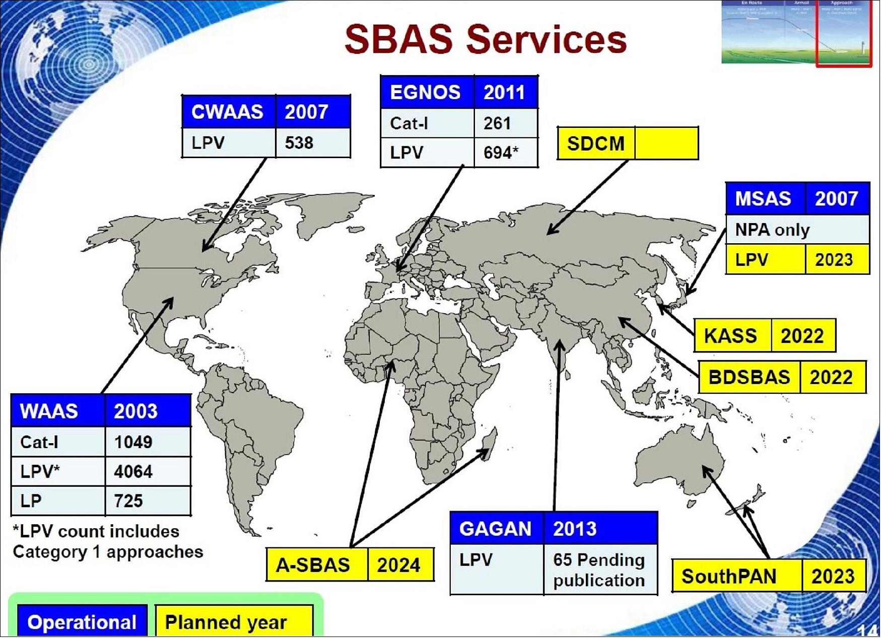
- “In addition, we are working with developers of other satellite-based augmentation systems around the globe to ensure they stay fully interoperable so for instance EGNOS-equipped aircraft can fly between continents on a seamless basis. Such Interoperability combined with the arrival of the other SBAS systems under development in other regions will lead to a quasi-global worldwide safety of life service coverage in the year 2030.”
• February 9, 2021: The European GNSS Agency (GSA) has selected Eutelsat Communications (Euronext Paris: ETL) for the development, integration and operation of its next-generation EGNOS GEO-4 service. 21)
- The contract agreed between Eutelsat and GSA covers 15 years of service provision and represents a total value of €100m, of which €85m subject to the confirmation of funds allocated to the EGNOS program from the European Union budget for the period 2021-2027.
- EGNOS is the European Geostationary Navigation Overlay Service that acts as an augmentation service to global positioning systems, to improve the reliability of positioning information. This is ensured by a crucial integrity message which is essential in aviation where the Global Navigation Satellite System (GNSS) alone does not satisfy strict operational requirements set by the International Civil Aviation Organization (ICAO). It is especially important during critical flight stages such as the final approach. Other transport means including maritime and rail benefit from this EGNOS Safety of Life service. EGNOS also increases the positioning accuracy for other land-based applications, notably precision farming, geomatics, and land management.

- Eutelsat already operates the EGNOS GEO-3 payload on its EUTELSAT 5 West B satellite which entered into service in February 2020. Built by Airbus Defence and Space, EUTELSAT HOTBIRD 13G satellite, which will host the EGNOS GEO-4 payload, is scheduled to be launched in the first half of 2022.
- Commenting on the agreement, Rodolphe Belmer, Chief Executive Officer of Eutelsat said: “We are delighted to have been entrusted once again by the GSA for this critical mission. It showcases the unparalleled coverage of our fleet as well as our technological expertise and reliability. Space technology continues to change the way we live, and we are delighted to support the GSA to ensure that European citizens get the most out of satellite navigation programs. We are looking forward to collaborating on other projects of this nature with GSA.”
• October 8, 2020: Sindal Airport in Denmark, the Czech Air Force, Slovenia Control and European Air Cargo in Sweden as Air Navigation Service Providers finally confirmed the availability of the EGNOS service in 2020. 22)
- The demand for EGNOS-based procedures across European airports is growing rapidly, with twenty new organizations signing EGNOS Working Agreements with ESSP SAS in 2019.
- The EGNOS service has also been successfully extended into non-ATS environments and in particular in Helicopter Emergency Medical Services (HEMS) operations. The first EWA signed with HEMS providers was established in summer 2019 with Norsk Luftambulanse, a HEMS rotorcraft operator which operates flights in Scandinavia.

- Over 2019 and 2020, 27 Air Navigation Service Providers (ANSPs) signed an EGNOS Working Agreement bringing their total number to 95 across Europe:
- ORO Navigacija (LT), Arendal Airport-Gullknapp (Norway), High Coast Airport (Sweden), ATS Hagfors (Sweden), SAERCO (Spain), Torsby Airport (Sweden), ESKM ATS (Sweden), Lycksele Airport (Sweden), Seinäjoki Airport (Finland), Ireland West Airport (Ireland), ANA Luxembourg (Luxembourg), Tréner Kft (Hungary), LGS (Latvia), Norsk Luftambulanse (Norway), SafeSkys (United Kingdom), Avinor AS (Norway), Györ-Per Airport (Hungary), Békés Airport (Hungary), Newcastle Airport (United Kingdom), Glasgow Prestwick Airport (United Kingdom), Trentino Trasporti (Italy), ANSP LHPP (Hungary), South Lapland Airport (Sweden), Sindal Airport (Denmark), Czech Air Force (Czech Republic), Slovenia Control (Slovenia) and European Air Cargo (Sweden).
- Sweden had the highest growth in terms of implementation of EGNOS closely followed by Hungary.
- The so-called PBN IR (Performed Based Rating, Instrument Rating) will further stimulate the implementation of EGNOS based procedures in most of the remaining airports because this Regulation makes it mandatory for the Air Navigation Service Providers to publish RNP approaches at all the runway ends without precision approaches before the end of 2020 and at all the rest of runway ends (already with a precision approach) by the beginning of 2024. ESSP will continue providing support to ensure that EGNOS is well served where needed.
- A recently-closed activity with Capgemini, in France, wanted to progress the market by building, integrating and testing a Prototype Multi Global Navigation Satellite System (GNSS) Reference Station.
- The prototype was to be based, to a large extent, on commercial off-the-shelf equipment and had to be able to demonstrate the compliance of this equipment with regards to stringent performance specifications.
- The contracting company, Capgemini, intended to use this activity to build its capacity and experience and make a name for itself as a Prime in the field of antenna and receiver technologies for ground stations.
- As such, this activity was primarily to de-risk the technology, develop the market and advance the consortium’s knowledge in the ground station arena.
- The activity led to the development of a prototype for the full sensor station - complete with computer technology, two receiving chains and the antenna.
- Characterization tests showed that the proposed Multi GNSS Reference Station has globally good performances in terms of acquisition and tracking of GNSS signals. The prototype software for the receiver was able to track Galileo signals with no functional issue. A prototype antenna also saw improved performance, and was able to meet the challenging reference station requirements of the Korean satellite-based augmentation system.
- Next, the system will continue to evolve to meet changing European station requirements (e.g. the transition from EGNOS v2 to EGNOS v3) and also integrating for new signals.
• June 10, 2020: GNSS and Earth observation experts came together at a webinar organized by the European GNSS Agency (GSA) on 26 May to discuss how combining Galileo and EGNOS navigation and positioning tools with the data and services offered by EU Earth observation program Copernicus can be used to improve food security and make agriculture in general more efficient and sustainable. 24)
- Disruptions caused by the COVID-19 pandemic have thrown the importance of our food supply chain into sharp focus. At the same time, synergies between positioning data from Galileo and EGNOS and Earth observation data from Copernicus offer huge untapped potential for making the agriculture sector more efficient, resilient and sustainable.
- It was to explore this potential and to drive the use of space technology in the service of sustainable agriculture and a more secure food chain that the EO4AGRI H2020 project organized this webinar, in collaboration with GSA, targeted at students, researchers, data analysts, participants in European, national and international projects, service and application developers, and other stakeholders.
Early Adopter
- The agricultural sector was an early adopter of Europe’s satellite augmentation service EGNOS and over 95% of agricultural receivers in Europe are currently EGNOS-enabled, with more than 65% of receivers Galileo-enabled also. “Galileo plays a key role in precision agriculture not only in positioning but also when combined with other technologies such as Copernicus. The coming High Accuracy Service and Navigation Message Authentication will mean a turning point in smart farming applications”, said María-Eva Ramírez from the European GNSS Service Centre (GSC).
- In agriculture, EGNOS-based solutions are used for low-value crop cultivation and low-accuracy operations such as ploughing, fertilizing and harvesting while Galileo receivers are used in a multi-constellation environment for high-value crop cultivation and precision operations such as sowing and transplanting. “EGNOS usage in European farming is a reality. Hundreds of thousands of cereal farmers benefit from free enhanced GPS accuracy. Thanks to EGNOS, crop productivity is increased and more sustainable farming is possible”, said Sofía Cilla from the European Satellite Service Provider (ESSP).
- “GNSS has become an integral part of smart, connected and integrated farm management solutions and is a key driver for precision farming across the whole crop cycle”, said Joaquín Reyes González, Market Development Technology Officer at the GSA.
Strength Through Synergy
- But it is when EU GNSS and Earth observation services work in synergy that the benefits are most keenly felt. Synergies between EGNSS (GSA) and Copernicus support a number of agriculture solutions, such as variable rate application, which enables the precise use of fertilizers and pesticides where and when they are most needed, thereby making the sector more resource-efficient and reducing its environmental footprint.
- “We just scratched the surface of what is possible when these two core components are put into use operationally. The combination of these two European flagship space projects is a key enabler of the Farm to Fork Strategy, the core of the European Green Deal, allowing for a fair, healthy and environmentally-friendly food system in Europe and beyond”, said David Kolitzus from GeoVille Information Systems and Data Processing.
- EGNSS and Copernicus also enable soil moisture monitoring, providing timely information on water availability and reducing the amount of water used by linking it to the moisture level needed in the soil for a particular crop. Synergies between the two programs also support the implementation of the Common Agricultural Policy, simplifying and digitizing processes related to subsidies control and enabling more efficient checks. “EGNSS and Copernicus are core components in digital farming,” Reyes González said.
• March 30, 2020: In response to the ongoing Coronavirus pandemic, ESA’s Directorate of Navigation has shifted to teleworking while also ensuring the continuity of essential tasks, in particular the continued delivery of positioning, navigation, and timing services of the European satellite navigation system Galileo and the augmentation system EGNOS. 25)
- The national, local and industrial decisions on travel, meetings and quarantine are impacting the ability to deliver all ongoing commitments, so measures are being taken to minimize their impact.
- Priority has been given to ensure continued operations of both EGNOS and Galileo, so the ESA Navigation Directorate has been supporting the European Global Navigation Satellite System Agency, GSA – the operator of Galileo and EGNOS, on behalf of the European Commission.
- In addition to ensuring business continuity in critical areas, the team is maintaining constant contact with the various stakeholders and several measures have been taken as follows:
a) The first two satellites of Galileo’s Batch 3 are currently based at the ESTEC Test Center in the Netherlands, for engineering tests ahead of launch. This test campaign has been suspended, based on the medical advice that too high a concentration of people would be needed on-site if testing were to continue.
b) These stored satellites are being monitored by staff visiting ESTEC every few days, to verify that all is in order.
c) Other Galileo-related testing continues with the aim of supporting future launches. ESTEC-based lifetime testing of the next set of rubidium atomic clocks is set to continue, involving on-site monitoring every few days.
d) Testing of passive hydrogen maser atomic clocks is also continuing, at the ESA-VSC High-Power Radio Frequency Laboratory in Valencia, Spain. The University of Valencia, hosting the Lab, has given permission for a few specialists to oversee the tests.
- In addition, the Directorate team has shifted to teleworking, using video and audio-conferences to continue meetings with the industries involved and thereby minimize the impact on the deliveries of EGNOS upgrades, Galileo Batch 3 satellites, and the preparatory work for Galileo Second Generation.
• March 27, 2020: The EGNOS geostationary satellite (GEO) ASTRA SES-5 (GEO-1/PRN 136) has been introduced in the operational platform replacing satellite INMARSAT 4F2 (PRN 126), which has become part of the EGNOS TEST Platform broadcasting the TEST Signal-In-Space (SiS). 26)
- With the successfully completion of the last scheduled GEO Swap, all swaps planned for the first quarter of 2020 have been finalized and the Operational EGNOS Space Segment is back to the nominal configuration with both ASTRA GEOs (PRN 123 and PRN 136).
• December 5, 2019: TAS (Thales Alenia Space) announced today that it has signed a new contract with ESA (European Space Agency), on behalf of the European Commission, to upgrade Europe’s EGNOS satellite navigation system. Via this contract Thales Alenia Space will develop a new version of EGNOS (version V242B), incorporating new advanced functionalities. 27)
Worth a total of about 78 million euros, this contract includes the following:
- expansion of the EGNOS SBAS coverage zone;
- installation of a new generation of reference stations (RIMS);
- improved algorithms in the computation center (CPF) to boost system performance;
- enhanced system security.
Certification and commissioning of this latest version is slated for 2023.
“Safety of Life” service an export success: The EGNOS system “Safety of Life” service, available since 2011, is used in aviation to allow aircraft to make precision approaches for landing, without requiring ground-based landing aids. Building on its expertise in this field, Thales Alenia Space signed a contract with the Korean space agency in 2016 to supply the Korean Augmentation Satellite System (KASS). Including “Safety of Life” navigation services, South Korea’s KASS regional system will initially be used for aeronautical applications. It will provide indispensable assistance during certain flight phases, especially landing, meaning that operators will not need landing aid infrastructures at airports. In the same dynamic, ASECNA selected Thales Alenia Space in early 2019 to conduct a Phase B project, including the provision of a pre-operational service from 2020 as well as a SBAS (Satellite-based Augmentation System) in sub-Saharan Africa, to support the significant growth of air traffic in this area thanks to an optimized satellite solution.
• January 26, 2018: EGNOS V3 will offer improved and secure Civil Aviation Safety of Life services for the next decade over Europe Program will ensure a full continuity of service and will be the first operational SBAS using both GPS and Galileo. 28)
- Developed by ESA on behalf of the European Commission and the European GNSS Agency (GSA), EGNOS V3 (European Geostationary Navigation Overlay Service) will provide augmented operational Safety of Life services over Europe that improve the accuracy and availability of user positioning services from existing GNSS (Galileo and GPS) and provides crucial integrity messages to EGNOS users with alerts within a few seconds in case of system degradation, consolidating EGNOS’ position as one of the leading edge GNSS Systems in the future.
- EGNOS V3 will thus offer improved Safety of Life (SoL) services performances (where people’s lives are potentially at stake) over Europe to Civil Aviation community and new applications for Maritime or Land users, and will improve robustness against increasing security risks, in particular cyber-security risks.
- EGNOS V3 will ensure a full continuity of service for the next decade and will be the first operational SBAS implementing the dual frequency and multi constellation world standard, with both GPS and Galileo, replacing EGNOS V2 which has been in operation since 2011.
• March/ April 2017: Aviation is increasingly using GNSS as the primary means for navigation. In particular, regional aerodromes are benefiting from the increased accessibility offered by EGNOS. The European Satellite Services Provider (ESSP) and the European GNSS Agency (GSA) explain how. 29)
- Funded by the European Union and managed by the European GNSS Agency (GSA), EGNOS services are provided by ESSP SAS, a pan-European Air Navigation Service Provider (ANSP) certified in accordance with Single European Sky Regulation 2096/2005. Developed in compliance with applicable ICAO standards, the EGNOS Safety of Life (SoL) service has been available since March 2011.
- Galileo benefits for aviation: Galileo is Europe’s global navigation satellite system with full operational capability planned for 2020. Galileo will bring multiple additional benefits to aviation since its OS provides two navigation signals, in the E1/E5a frequencies, interoperable with GPS (L1/L5), the most extensively currently used GNSS constellation in aviation. Thus, more frequencies, signals and satellites are available for aircraft receivers to compute its position, enabling improved navigation performances and higher robustness compared to those attainable when using only one constellation or just one frequency. The future standards required for operational approvals and upgraded augmentation systems [ABAS (Aircraft Based Augmentation System), SBAS and GBAS] are being developed to ensure interoperability and to take full advantage of the DFMC (Dual Frequency Multi-Constellation) scenario, in particular: RAIM (Receiver Autonomous Integrity Monitoring); EGNOS V3; and CAT II-III operations.
- Finally, additional benefits will come from the use in aviation of the Galileo Search and Rescue Service (SAR), the EU contribution to the COSPAS-SARSAT international system, which enables near real-time reception of distress messages transmitted from anywhere on Earth and feedback to the distress emitting beacon, in some cases.
MSAS (Multi-functional Satellite Augmentation System), Japan
The MTSAT Satellite Augmentation System (MSAS) is the Japanese Satellite Based Augmentation System (SBAS) System: a GPS Augmentation system with the goal of improving its accuracy, integrity, and availability, and that uses the Multifunctional Transport Satellites (MTSAT) owned and operated by the Japanese Ministry of Land, Infrastructure and Transport and the Japan Meteorological Agency (JMA).
The Japanese government launched the MTSAT (Multifunctional Transport SATellite) in 2005 and 2006 for preparing MSAS in the west Pacific area. First tests were accomplished successfully, and MSAS system for aviation use was declared operational in September 27, 2007 providing a service of horizontal guidance for En-route through Non-Precision Approach 30)
MSAS Architecture
MSAS works by processing GPS data collected by a network of reference stations to generate the SBAS message which is uploaded to the GEO satellites. The GEO satellites broadcast this information to the user receivers, which compute the aircraft positioning and inform on potential alert messages. 31)
The main layers of MSAS architecture are:
• MSAS Ground Segment: The ground segment is composed of four Ground Monitor Station (GMS) that collect information on the GPS and MTSAT signals. Then, the GMS send their data to two Master Control Station (MCS) in Kobe and Hitachiota, that compute precise differential corrections and integrity bounds and send them to the MTSAT satellites for rebroadcast to the User Segment. The MSAS Ground Segment is completed with two Monitor and Ranging Station (MRS), whose purpose is primarily the correct orbit determination of the MTSAT satellites.
• MSAS Space Segment: The space segment consists of two geosynchronous satellites (GEO): the Multifunctional Transport Satellites (MTSAT). These satellites are used also for meteorological purposes. Their navigation payloads are in charge of broadcasting the correction messages generated by the Master Control Stations for reception by the User Segment.
• MSAS User Segment: The user segment is the GPS and SBAS-enabled receiver, which uses the information broadcast from each GPS satellite to determine its location and the current time, and receives the MSAS corrections from the Space Segment.
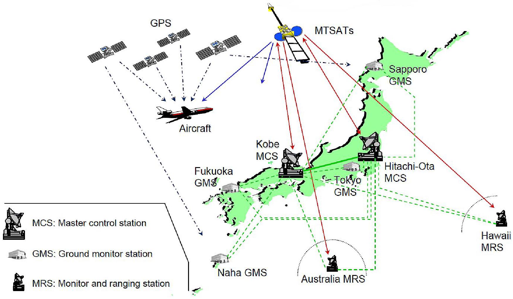
Kobe/Hitachiota: 2 MCS (Master Control Stations)
- System Monitoring/Control
- Satellite Error Calculation
- MTSAT Orbit Determination
- Ionospheric Delay Correction Calculation
- Integrity Augmentation Processing
- GPS/MTSAT Signal Reception/Collection
Sapporo/Tokyo/Fukuoka/Naha: 4 GMS (Ground Monitor Stations)
- GPS/MTSAT Signal Reception/Collection
Hawaii/Australia: 2 MRS (Monitor & Ranging Stations)
- GPS/MTSAT Signal Reception/Collection
MSAS provides augmentation information, which improves the accuracy, reliability and safety of GPS, for aircraft using GPS navigation. MSAS receives GPS signal at the Ground Monitor Stations and the Monitor & Ranging Stations, checks operational status of GPS, analyze GPS error and ionospheric delay, and then broadcasts augmentation information through MTSAT (Multi-functional Transport Satellite) from the Master Control Stations.
NEC manufactured and delivered MSAS under contract with the Civil Aviation Bureau, Ministry of Land, Infrastructure, Transport and Tourism. 32) 33)
![Figure 31: RNAV / RNP implementation [image credit: ENRI (Electronic Navigation Research Institute)]](https://www.eoportal.org/ftp/satellite-missions/s/SBAS_300622/SBAS_Auto19.jpeg)
The RNP (Required Navigation Performance) is similar to RNAV (Area Navigation); but, RNP requires on-board navigation performance monitoring and alerting capability to ensure that the aircraft stays within a specific containment area.
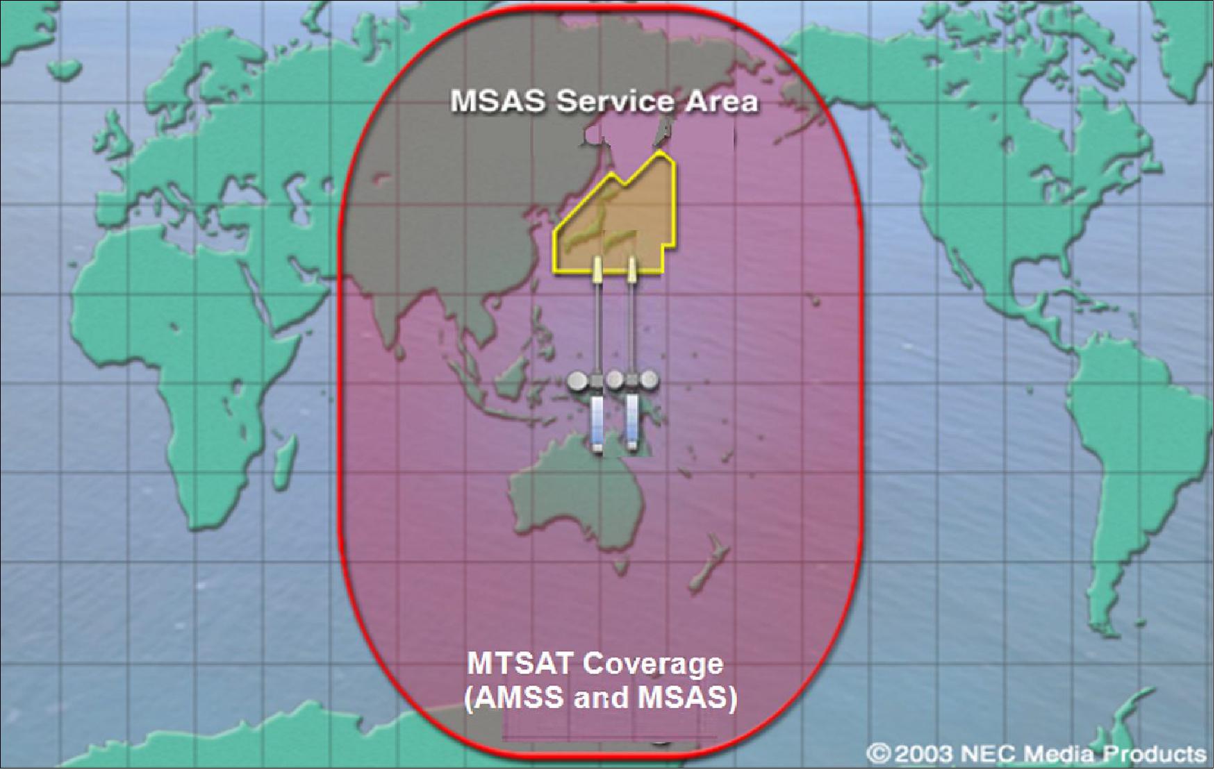
MSAS Upgrade
• MSAS V2 (2020-)
- System update with QZSS (Quasi-Zenith Satellite System , Michibiki). QZSS (Michibiki) has been in operation since November 2018 to develop a satellite positioning service that can be used stably in all locations at all times. This system is compatible with GPS satellites and can be utilized with them in an integrated fashion. In this way, the satellite positioning service environment was advanced dramatically.
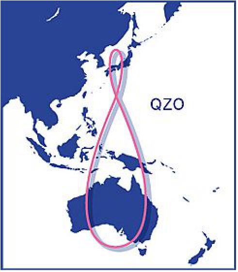
- RNAV (en-route to RNP-0.3) in Fukuoka FIR (Same as current MSAS)
• MSAS V3 (2023 (TBD)-)
- Additional GEOs and GMSs
- LPV (Localizer Performance and Vertical) guidance implementation
• MSAS V4
- DFMC (Dual-Frequency and Multi-Constellation) SBAS
- Validation activities by ENRI (2017-)
GAGAN (GPS Aided Geo Augmented Navigation)
ISRO (Indian Space Research Organization) is committed to provide the satellite based Navigation services to meet the emerging demands of the Civil Aviation requirements and to meet the user requirements of the positioning, navigation and timing based on the independent satellite navigation system. To meet the Civil Aviation requirements, ISRO is working jointly with Airport Authority of India (AAI) in establishing the GPS Aided Geo Augmented Navigation (GAGAN) system. To meet the user requirements of the positioning, navigation and timing services based on the indigenous system, ISRO is establishing a regional satellite navigation system called Indian Regional Navigation Satellite System (IRNSS). GAGAN/IRNSS is the Indian SBAS (Space Based Augmentation System) jointly developed by ISRO and AAI to provide the best possible navigational services over the Indian FIR (Flight Information Region) with the capability of expanding to neighboring FIRs. 34)
GAGAN Stability tests were successfully completed in June 2013. The overall performance of the systems was reviewed by the review committee. As part of certification activity, DGCA (Directorate General of Civil Aviation) personnel visited GAGAN complex, Kundalahalli in Bengaluru and carried out final inspection activities on Indian Land Uplink Station (INLUS), Indian Master Control Centre (INMCC), Indian Reference Earth Station (INRES) and other facilities.
The implementation of GAGAN has numerous benefits to the aviation sector in terms of fuel saving, saving in equipment cost, flight safety, increased air space capacity, efficiency, enhancement of reliability, reduction in work load for operators, coverage of oceanic area for air traffic control, high position accuracy, etc. The quantum of benefits in the aviation sector would depend on the level of utilisation of such benefits.
Some of the benefits GAGAN is expected to bring for Civil Aviation sector are:
• Safety benefits – Vertical guidance improves safety, especially in adverse weather conditions
• Reduction of circling approaches
• Environmental benefits–Approach with Vertical Guidance procedures will help facilitate better energy and descent profile management during the final approach
• Global seamless navigation for all phases of flight including arrival, departure, oceanic and en route
• Allow direct routings, multiple approaches resulting in considerable fuel savings to airlines and provide for capacity enhancement of airports and airspace.
In addition to the aviation sector, GAGAN is expected to bring benefits to other sectors like:
• Navigation and Safety Enhancement in Railways, Roadways, Ships, Spacecraft
• Geographic Data Collection
• Scientific Research for Atmospheric Studies
• Geodynamics
• Natural Resource and Land Management
• Location based services, Mobile, Tourism, etc.
IRNSS will provide two types of services, namely, Standard Positioning Service (SPS) which is provided to all the users and Restricted Service (RS), which is an encrypted service provided only to the authorised users. The IRNSS System is expected to provide a position accuracy of better than 20 m in the primary service area.
Some applications of IRNSS are:
• Terrestrial, Aerial and Marine Navigation
• Disaster Management
• Vehicle tracking and fleet management
• Integration with mobile phones
• Precise Timing
• Mapping and Geodetic data capture
• Terrestrial navigation aid for hikers and travellers
• Visual and voice navigation for drivers.
GAGAN Architecture
The GAGAN system is interoperable with other international SBAS systems such as the U.S. WAAS (Wide Area Augmentation System) , the EGNOS (European Geostationary Navigation Overlay Service), and the Japanese MSAS (MTSAT Satellite Augmentation System), and provides seamless air navigation across regional boundaries. 35)
GAGAN Elements: The GAGAN system consists of the following elements for the effective implementation of SBAS over India (Figure 34).
1) Indian Reference Station (INRES) — at 15 locations across India
2) Indian Master Control Center (INMCC) —two at Bangalore
3) Indian Land Uplink Station (INLUS) — three stations, two at Bangalore and one at New Delhi
4) Geostationary satellites (GSAT8/ GSAT10) in orbit and one on-orbit spare in GSAT-15 launched on November 10, 2015
5) A data communication subsystem —two optical fiber communication (OFC) circuits and two very small aperture terminal (VSAT) circuits. The following sections describe each element in greater detail.
INRES (Indian Reference Station). The INRES stations collect measurement data and broadcast message from all the GPS and GEO satellites in view and forward them to the INMCC for further processing. The 15 INRES stations are established a t Ahmedabad, Bangalore, Jammu, Guwahati, Kolkata, New Delhi, Port-Blair, Trivandrum, Jaisalmer, Goa, Porbandar, Gaya, Dibrugarh, Nagpur and Bhubaneshwar.
INMCC (Indian Master Control Center). The data collected by each INRES across the country are transmitted to INMCC in real time (every second) and processed for the generation of correction and integrity parameters,in the form of SBAS messages. The generated SBAS messages are sent to INLUS for further processing.
INLUS (Indian Land Uplink Station). The INLUS receives the SBAS messages from INMCC, formats them for GPS compatibility and uplinks the SBAS messages to GEO Stationary satellite for broadcast to the user community. The SBAS messages contain information that allows SBAS receivers to remove errors in the GPS position solution, thereby allowing for a significant increase in location accuracy with reliability. Along with the corrections, the confidence parameters (integrity) are also computed and provided to the users as messages. The messages are up linked in C-band to GSAT-8/GSAT-10 GEO satellite through Indian Land Uplink Station (INLUS) which are down linked in L1 & L5 band to the users. The broadcast messages are used by SBAS compatible receivers which compute its position while applying corrections over GPS signals.
GEO Satellite. ISRO is responsible for providing GEO Satellites (SPACE segment) to the GAGAN program. Three GEO satellites GSAT-8 (see accompanying photo), GSAT-10, and GSAT-15 carry the GAGAN payload. GSAT-8 (located at 55 º East) and GSAT-10 (83º East) are already transmitting GAGAN SIS (Signal in Space) with PRN127and 128. The GSAT-15 carrying the GAGAN payload is stationed at 93.5 degrees East and has been allocated PRN132.
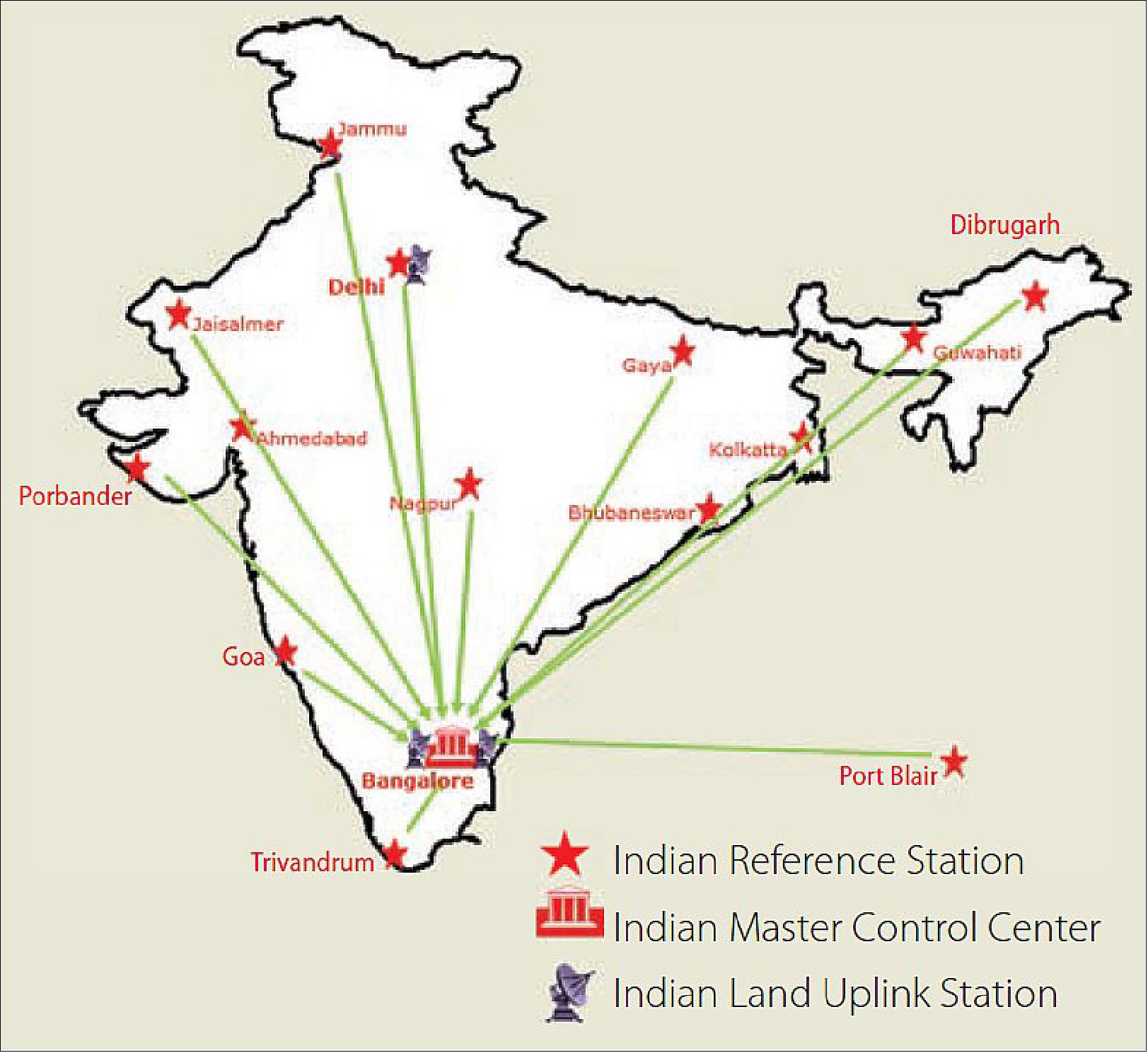
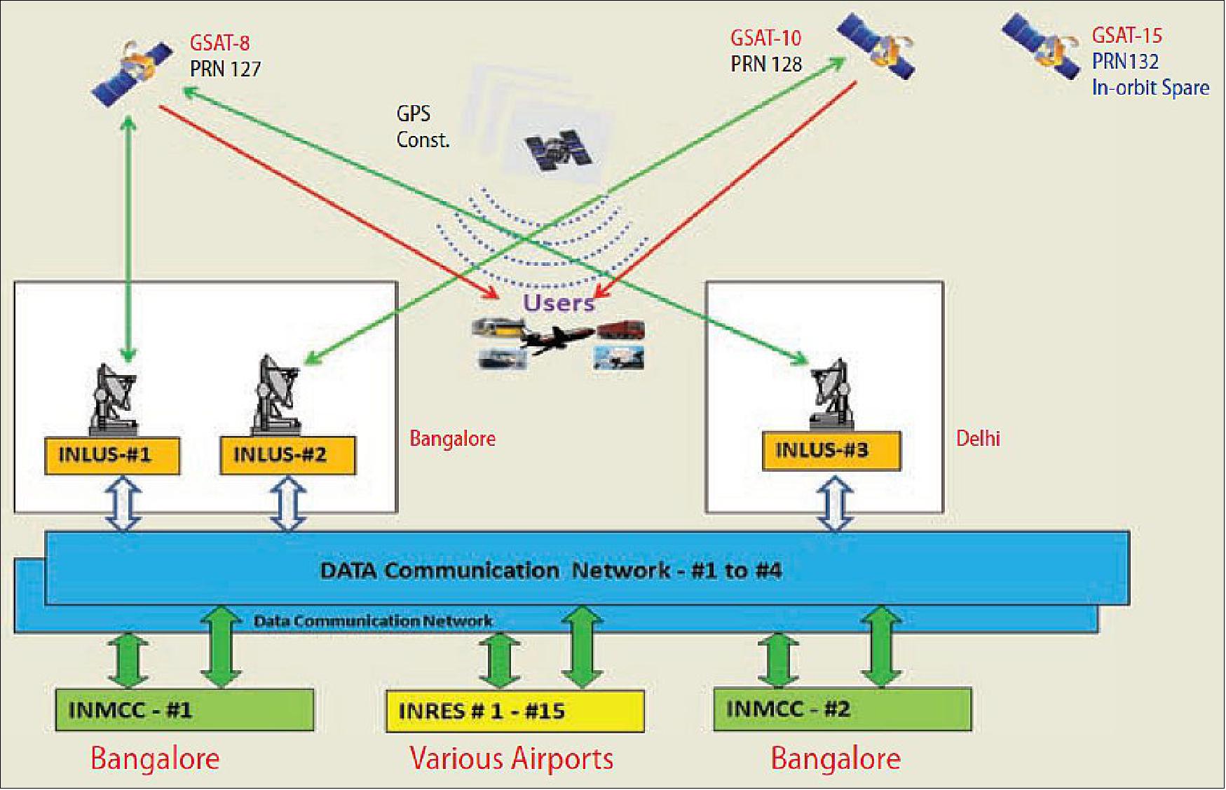
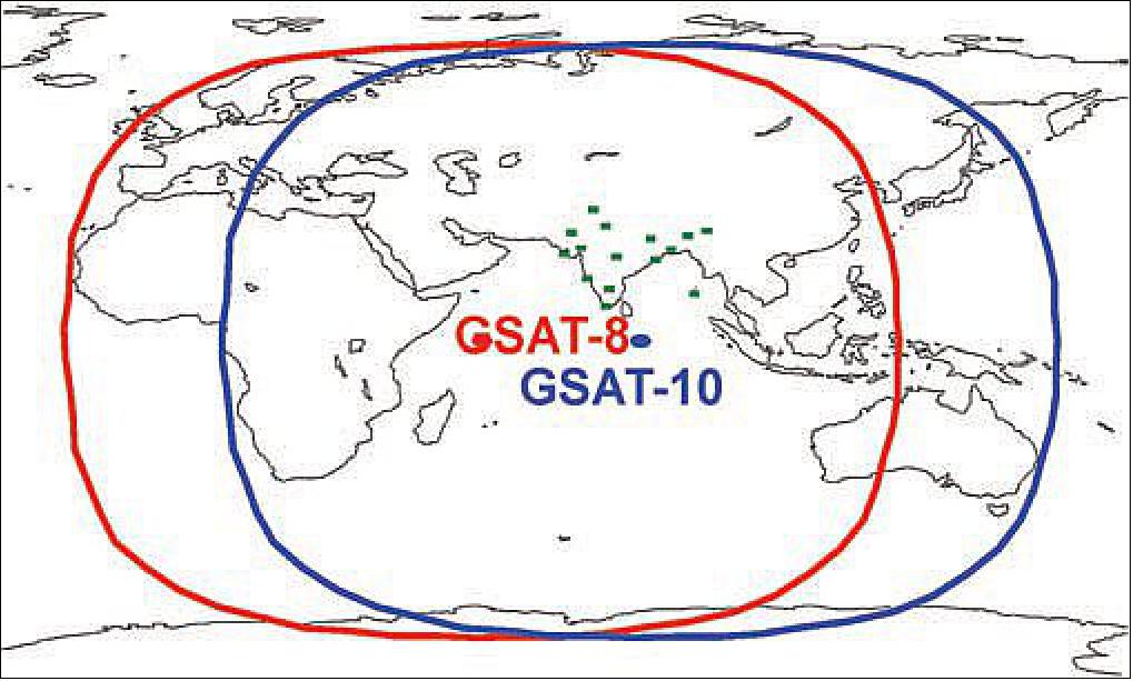
Ionospheric Model Development
The ionospheric behavior over the low-latitude Indian regions is not quiet and is characterized by such features as scintillation, plasma depletion, large-scale energy density gradients, and so forth. To ensure optimal performance of GAGAN, ionospheric irregularities must be detected and the statistical confidence bounds adjusted accordingly.
Need for a Region-Specific Model. To meet the required GAGAN performance, development and implementation of the best suitable ionosphere model were needed, a model that would be applicable to the Indian region. Moreover, preferentially the selected ionosphere-model algorithm should not call for changes in the existing SBAS message structure because any changes in the ICAO Minimum Operational Performance Requirements (MOPS) for GPS/WAAS airborne equipments-DO-229 would require agreement among all member states. Certifying GAGAN system with MOPS changes would have been a very time-consuming process.
In constructing the model, grid ionosphere vertical error (GIVE) confidences must bind the errors not only at the ionosphere grid points but also for all interpolated regions between the grid points. Moreover, the error bound must be valid for both the nominal and the disturbed ionosphere. In order to capture large-scale features of the equatorial ionosphere anomaly, the model must provide an approach to overcome the inadequacy of the thin shell model (of electrons) over equatorial regions and capture the complex three-dimensional nature of the equatorial ionosphere.
Features of the Region-Specific Model Required for Indian SBAS. The region specific ionosphere model must have the following characteristics:
• implementable
• able to demonstrate integrity
• provide adequate availability for the precision user
• backward compatibility
• reduce modeling errors and support precision approach service in the Indian region
• define the equatorial ionosphere with sufficient accuracy and integrity
• upon safety certification, be able to support operationally useful availability of vertical guidance in the service area over the landmass of the Indian FIR (Flight Information Region).
ISRO GIVE Model – Multi Layer Data Fusion (IGM-MLDF). In order to model the vertical movement of the ionosphere, the IGM-MLDF Model is designed to capture the ionosphere variability at two different ionospheric electron shell heights and finally provide a value for the user at a 350-kilometer shell height using a weighted average method. The model ensures that the broadcast GIVEs have a sufficiently high level of integrity so that the user ionosphere vertical errors (UIVEs) computed by user receivers will bound their vertical ionosphere errors with a very high probability. The GIVE guarantees the integrity of UIVEs, not only at the grid point but at all points of the four grid cells surrounding the grid point. The algorithm provides the delay and the confidence values for the user, resulting in improved accuracy and availability.
The algorithms were analyzed and reviewed, and performance of each of these was examined based on exhaustive studies carried out using INRES and total electron count (TEC) data over Indian region (Figure 37). Several nominal and storm (disturbed ionosphere) days were selected and the performance of the candidate algorithms was tested on these days.
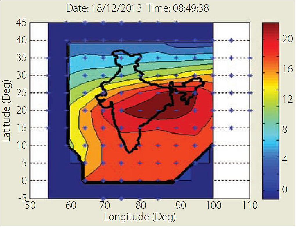
A down-selected IGM-MLDF algorithm was further improved through extensive review by expert teams aiding in a series of performance enhancements followed by an extensive analysis to tune parameters in the algorithm and determine the achievable accuracy, availability, continuity, and integrity of GAGAN service. The key function of the algorithm is to compute the delays and confidences (fit error) at various shell layers and combine them at 350 kilometers, which does not require any MOPS changes.
This model is incorporated into the main GAGAN operational software by M/S Raytheon to compute and provide ionospheric corrections and integrity factors needed to meet the APV requirements.
Performance Evaluation
Regular performance evaluation is a key activity to estimate a system’s utility, effectiveness, and suitability to meet the desired requirements. Figures 38 through 41 provide a few snapshots of performance monitoring of GAGAN.
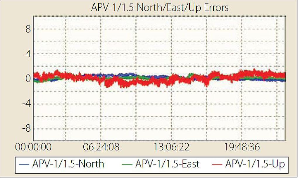
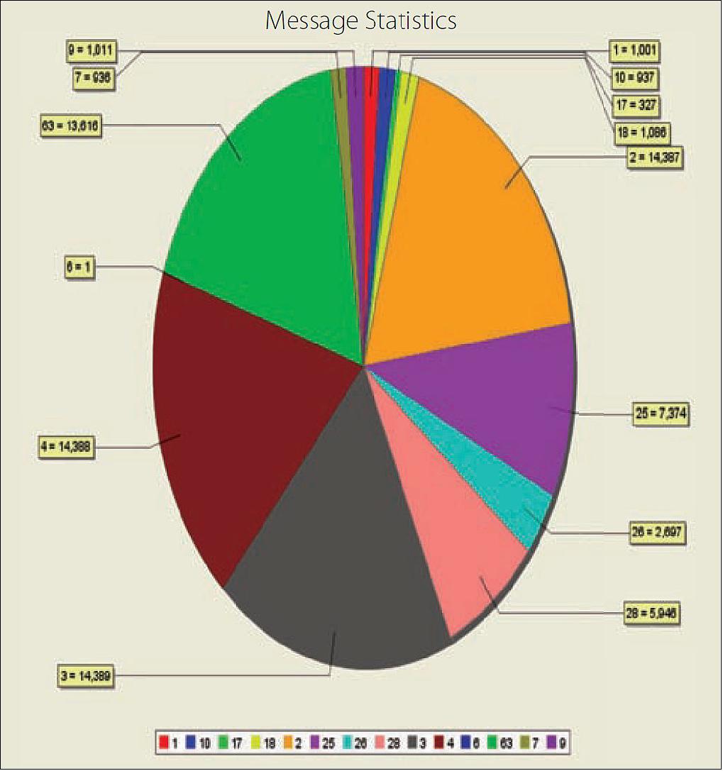
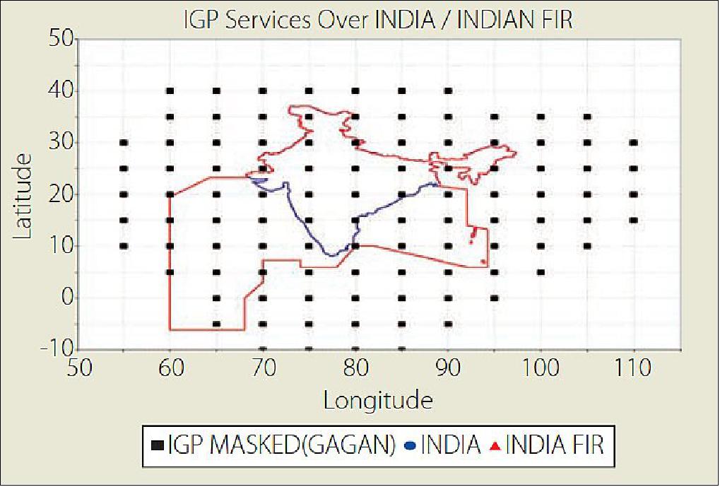
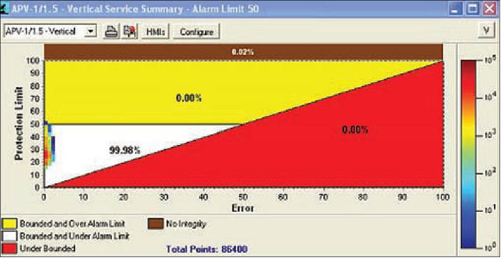
Signal-In-Space Validation Through Dynamic Test
To obtain a preliminary assessment of GAGAN performance, a dynamic flight test was conducted between Hyderabad and Bangalore (Figure 10) using a GAGAN receiver on board an ISRO aircraft.
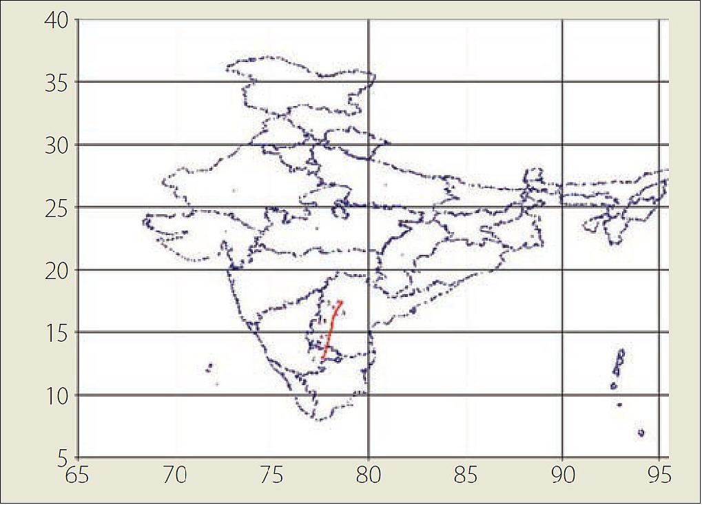
The dynamic flight test results revealed the following:
1) The accuracy of GAGAN along East with reference to the truth (DGPS East reference) is less than 7.6 meters, 100 percent of the time, which is within the GAGAN performance requirement for all the sorties.
2) The accuracy of GAGAN along North with reference to the truth (DGPS North reference) is less than 7.6 meters, 100 percent of the time, which is within the GAGAN performance requirement for all the sorties.
3) The accuracy of GAGAN along Up with reference to the truth (DGPS Up reference) is less than 7.6 meters.
4) The position standard deviation of latitude, longitude, and altitude were found to be less than 4 meters, which indicates that the position accuracies of the GAGAN are well within the 7.6-meter requirement.
GAGAN Certification
The Director General of Civil Aviation (DGCA) formed a Technical Review Team (TRT) to examine specific safety-related artifacts and hazard records and to provide recommendations for resolving any observed issues. AAI had engaged the MITRE Corporation to support the certification effort. A two-step certification decision was adopted for GAGAN implementation. The TRT reviewed the integrity-related artifacts and hazard records and recommended the findings to the certifying authority (DGCA) for certification.
Status of GAGAN Operations
• January 7, 2019: India’s civil aviation regulatory agency is postponing the requirement for aircraft registered in India to be equipped with GAGAN (GPS Aided Geo Augmented Navigation system) compatible avionics. 36)
- GAGAN is a satellite based augmentation system (SBAS) designed to enable aircraft to fly precision approaches with vertical guidance to airfields with charted approaches. India’s ministry of civil aviation mandated GAGAN equipage by Jan. 1, 2019 in June 2016 and has now moved the deadline to June 30, 2020.
- “All the aircraft being imported for registration on or after 30.06.2020 shall be required to be suitably equipped with GAGAN equipment,” the public notice published by the Director General of Civil Aviation (DGCA) said.
- GAGAN works by augmenting and relaying data from GPS satellites with the help of two geostationary satellites, and 15 earth-based reference stations operating throughout the Indian flight information region.
- The reference stations pick up signals from the satellites and relay them to GAGAN-enabled receivers on aircraft. The aircraft’s signal accuracy is then determined and any errors, such as those caused by electrical disturbances in the atmosphere, are corrected and sent to the satellites. The satellites then relay the corrected information back to the aircraft to provide better accuracy than can be achieved using GPS alone.
- DGCA has struggled to incentivize India’s airlines and smaller aircraft operators to equip with GAGAN avionics since then. For example, in December 2016, DGCA met with airlines and other stakeholders to discuss the low usage rate of GAGAN 18 months after its launch to warn them of consequences if usage did not increase. Those consequences never materialized.
- The regulator has also witnessed presentations from airlines showing how expensive the upgrade would be for aircraft within their fleet. Cost has been the primary inhibitor preventing airlines from equipping with GAGAN receivers.
- “We understand the GAGAN implementation has been deferred to June 30, 2020," a representative for IATA (International Air Transport Association) told Avionics International.
- "We expect that individual airlines should have the freedom to assess whether to invest in SBAS based on their operational needs and if there is a business case to justify the investment," he said.
- Many of India’s large and small commercial carriers will find the delay as a financial relief while dealing with surging jet fuel prices. Indigo, a low cost airline based in Haryana, India, reported a net loss of $89 million for its second quarter fiscal year 2019 in October. During that same period, India’s longest running private airline, Jet Airways, reported a net loss of $178 million.
- State run Air India and Spice Jet also reported quarterly losses throughout 2018. All of the carriers note that their losses were primarily driven by rising jet fuel costs.
- DGCA has not indicated that there will be any type of exemption policy implemented with the postponing of its GAGAN mandate.
GLONASS — SDCM (System of Differential Correction and Monitoring)
The Soviet Union began development of GLONASS in 1976 just a few years after work started on GPS. The first satellite was launched in 1982 and a fully populated constellation of 24 functioning satellites was achieved in early 1996. However, due to economic difficulties following the dismantling of the Soviet Union, by 2002 the constellation had dropped to as few as seven satellites. But the Russian economy improved, and restoration of GLONASS was given high priority by the Russian government. The satellite constellation was gradually rejuvenated using primarily a new modernized space-craft, GLONASS-M. 37)
The new design offered many improvements, including better onboard electronics, a longer lifetime, an L2 civil signal, and an improved navigation message. The GLONASS-M spacecraft still used a pressurized, hermetically sealed cylinder for the electronics, as had the earlier versions. Today, 26 functional GLONASS-M satellites are on orbit, 22 of them in service and providing usable signals, with four more having reserve status. A full constellation of 24 satellites should be available later this year with launches of several GLONASS-M satellites and the latest variant, the GLONASS-K satellite
GLONASS-K satellites are markedly different from their predecessors. They are lighter, use an unpressurized housing (similar to that of GPS satellites), have improved clock stability, and a longer, 10-year design life. They also include, for the first time, CDMA (Code Division Multiple Access) signals accompanying the legacy FDMA (Frequency Division Multiple Access) signals. There will be two versions: GLONASS-K1 will transmit a CDMA signal on a new L3 frequency, and GLONASS-K2, in addition, will feature CDMA signals on L1 and L2 frequencies. The first GLONASS-K1 satellite was launched on February 26 and is now undergoing tests.
GLONASS is being further improved with a SBAS (Satellite-Based Augmentation System). Called the SDCM ( System of Differential Correction and Monitoring), it will use a ground network of monitoring stations and Luch geostationary communication satellites to transmit correction and integrity data using the GPS L1 frequency. The first of these satellites, Luch-5A, will be launched this year. In this month’s column, a team of authors from Russian Space Systems, a key developer of navigation and geospatial technologies in the Russian aerospace industry, describes the new L3 CDMA signal to be broadcast by GLONASS-K satellites and the progress to date in developing the SDCM augmentation system.
The Joint Stock Company “Russian Space Systems” (JSC RSS) is a developer of ICD (Interface Control Document) and a head responsible for SDCM creation. JSC RSS is responsible for development, coordination, revision, maintenance an official distribution of ICD. ICD shall be approved by duly authorized representatives of Federal Space Agency (Roskosmos) and enters into effect upon approval by Head of Roskosmos. 38)
Navigation Signals
The main task for GLONASS development is an extension of the ensemble of navigation signals. This extension means that new CDMA signals in the L1, L2, and L3 bands will be added to the existing FDMA signals. The GLONASS satellites will keep broadcasting the legacy signals until the last receiver stops working.
The first phase in the implementation of CDMA technology on GLONASS-K satellites includes a new signal in the L3 band on a carrier frequency of 1202.025 MHz. The first GLONASS-K satellite was launched on February 26, 2011, and is undergoing tests. The ranging code chipping rate for the CDMA signal is 10.23 megachips per second with a period of 1 milliseconds. It is modulated onto the carrier using quadrature phase-shift keying (QPSK), with an in-phase data channel and a quadrature pilot channel. The signal spectrum is shown in Figure 43.
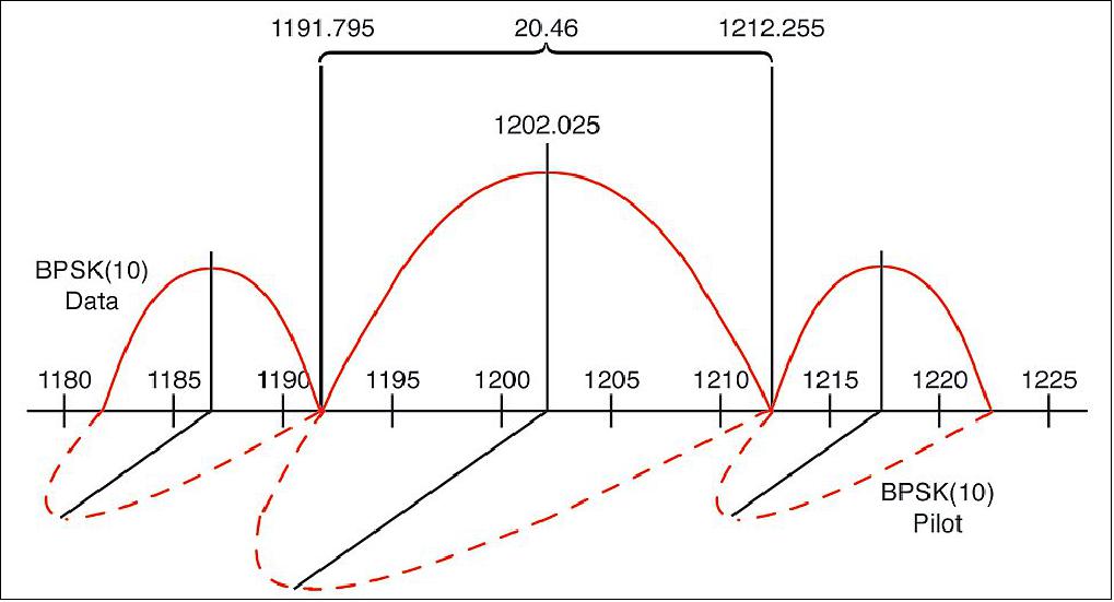
A block diagram of how the GLONASS L3 signal is formed is presented in Figure 44. The set of possible ranging codes consists of 31 truncated Kasami sequences. (Kasami sequences are binary sequences of length 2m – 1 where m is an even integer. These sequences have good cross-correlation values approaching a theoretical lower bound. The Gold codes used in GPS are a special case of Kasami codes.) The full length of these sequences is 214 – 1 = 16,383 symbols, but the ranging code is truncated to a length of N = 10,230 with a period of 1 milliseconds and with the following initial state (IS) in the generator (G) registers: G2 – IS = 00110100111000, G1 IS = n, G3 IS = n + 32. It these equations, n is the system number of the satellite in the orbit constellation. For these codes, inter-channel jamming is about –40 dB.
The navigation message symbols (NSs) are transmitted at a rate of 100 bits per second with half-rate convolution coding (CC) with a memory of 6. This means that the duration of an NS is 10 milliseconds and the duration of the CC symbols is 5 milliseconds. The CC switch (see Figure 44) should be in the lower position for the first half of each NS.
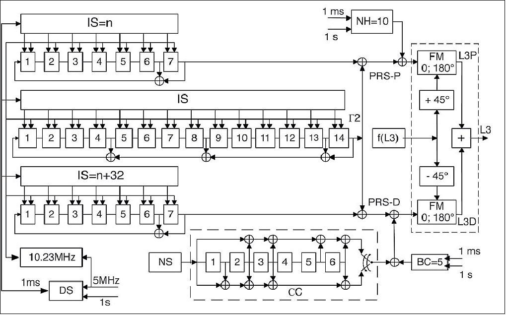
The pseudorandom sequence of the L3 data signal, PRSD, is modulo-2 summed with a periodic 5-bit Barker code (BC = 00010) before phase modulation. Barker code symbols have a duration of 1 millisecond and are synchronized with the pseudorandom code symbols. The pseudorandom sequence of the L3 pilot signal, PRS-P, is modulo-2 summed with a 10-bit Neuman-Hoffman code (NH = 0000110101). The Neuman-Hofman code symbols have a duration of 1 millisecond and are synchronized with the information symbols. The Barker and Neuman-Hoffman codes are used for CC synchronization in the L3 user’s receiver.
The navigation message superframe (2 minutes long) will consist of 8 navigation frames (NFs) for 24 regular satellites in the GLONASS first modernization stage and 10 NFs (lasting 2.5 minutes) for 30 satellites in the future. Each NF (15 seconds long) includes 5 strings (3 seconds each). Every NF has a full set of ephemerides for the current satellite and part of the system almanac for three satellites. The full system almanac is broadcast in one superframe. A time marker is located at the beginning of a string and given as a number of a string within the current day in the satellite time scale.
The GLONASS system and the satellites’ time scales are coordinated with the Russian national time scale, UTC(SU), which is periodically adjusted for a leap seconds. A special flag, A, is used in each frame to inform users about an anomalous fifth string of this frame. If A = 0, the fifth string will be normal with a 3-second duration; if A = 1, the fifth string will be either 2 seconds or 4 seconds. The correction value (+1 second or –1 second) is also transmitted in the special NF flag, KP. If KP = 11, the fifth string will be shorter due to a correction of –1 second; if KP = 01, it will be longer due to a correction of +1 second. A user should not use the short string. A string is lengthened by adding “0” to the normal string. This algorithm is implemented with the objective of simplifying the time scale correction process in user equipment.
Modulation and Multiplexing. There are intensive studies being carried out for developing new CDMA signals in the L1 and L2 bands in addition to the L3 signal described above. The main difficulties to be overcome in these studies are to ensure a low-power spectral density (PSD) of –238 dBW/m2/ Hz in the 1610.6–1613.8 MHz radio astronomy band and the multiplexing of more than two signal components, providing a constant signal level.
The first task could be solved by using a modulation with a low PSD level in the radio astronomy band, such as a binary offset carrier (BOC) modulation with a subcarrier frequency of 5.115 MHz and a spreading code chipping rate of 2.5575 megachips per second (BOC(5, 2.5)) as shown in Figure 45.
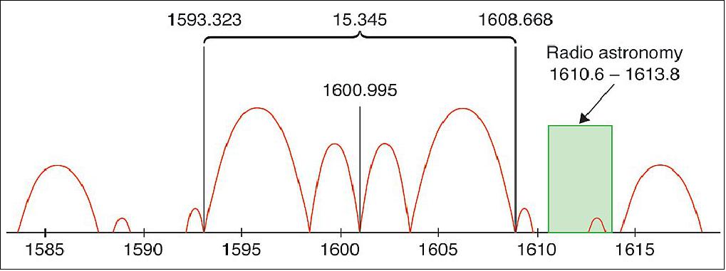
There are two well-known methods of signal multiplexing — time multiplexing and amplitude equalizing. The time multiplexing technique is used for the GPS L2C signal, while the amplitude equalizing method is used for the composite BOC (CBOC) signals in the Galileo E1/L1 band and the alternative BOC (AltBOC) signals in E5a-E5b bands. This method has the disadvantage of about 10–16 percent loss of the transmitter power on the equalization. However, it has an advantage: simple user equipment architecture and, more importantly, the possibility of step-wise implementation of the multicomponent signal. The step-wise approach is compatible with older receivers. New user equipment will be able to track both old and new signal components, as well as a combined signal consisting of old and new components. Vector and phase diagrams for two-, four-, and six-component AltBOC signals are shown in Figure 46. Even with six components, losses are lower than about 16 percent, but it is possible to avoid any loss using time multiplexing. That is why the final decision about future GLONASS signals has not yet been made.
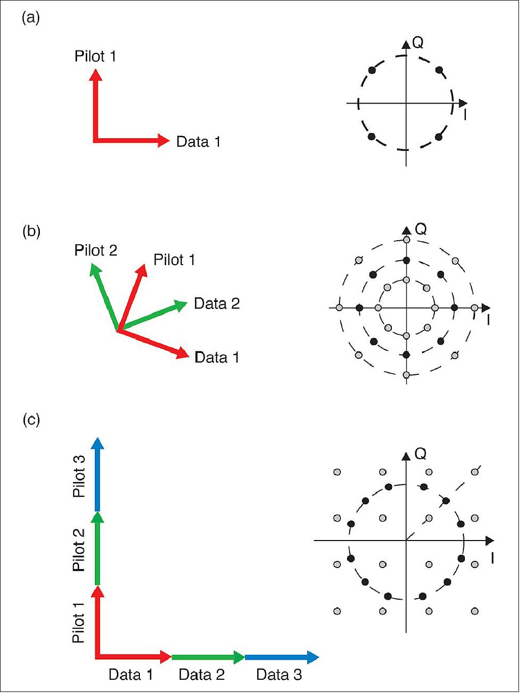
There have been extensive studies on the definition of the ensemble of code sequences with a minimum level of interchannel jamming. It was found that the jamming level for random shifts does not depend on the code type, but rather depends on the number of symbols, N, in a period. Crosscorrelation functions for Kasami 4095 and Weil 10230 codes are shown in Figures 47 and 48. (Kasami codes, as previously mentioned, are being used for the GLONASS L3 CDMA signal. Weil codes are prime length sequences constructed from the well-known Legendre sequences and are used for the GPS L1C signal.) For comparison, we show cross-correlation functions for random codes with equal lengths on the same figures. It is obvious that the histograms of predefined and random codes are close to being equal. Sidelobe dispersion levels are lower than 0.1 dB.
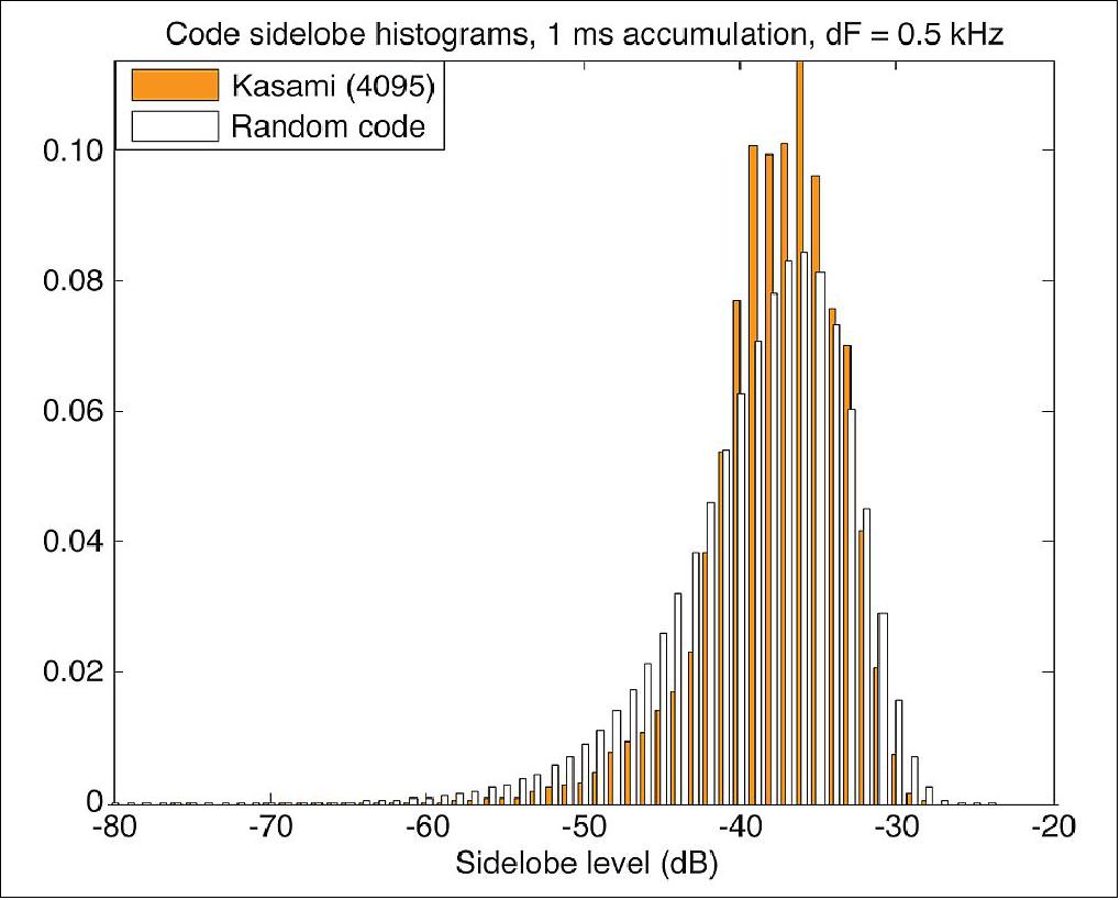
The results obtained from the studies allow us to draw a conclusion about the invariance of the stochastic characteristics of inter-channel interference using a code structure with a fixed length of N symbols. That is why it is possible to choose an ensemble of binary code sequences on the basis of generation simplicity.
GLONASS Augmentation Development
SDCM has been under development since 2002. The main elements of the system, including the network of reference stations in Russia and abroad, the central processing facility (CPF), and the SDCM information distribution channel, have been designed.
Ground Stations. The SDCM uses 14 monitor stations in Russia and two in Antarctica at Russia’s Bellingshausen and Novolazarevskaya research stations. Eight more monitor stations will be added in Russia and several more outside Russia. The additional overseas stations may include sites in Latin America and the Asia-Pacific region.
Central Processing. Raw measurements (GLONASS and GPS L1 and L2 pseudorange and carrier-phase measurements) from the ground stations come to the SDCM CPF (Central Processing Facility). The CPF calculates the precise satellite ephemerides and clocks, controls integrity, and generates the SBAS messages. The format of these messages is compliant with the international standard also used by the Wide Area Augmentation System (WAAS), the European Geostationary Navigation Overlay Service (EGNOS), and the Japanese Multi-functional Transport Satellite (MTSAT) Satellite-based Augmentation System (MSAS).
Format Limitations. The current SBAS format has a limited capability for broadcasting corrections for GLONASS and GPS satellites combined. There is space for only 51 satellites, insufficient for the current number of satellites on orbit. As a result, studies are looking into the efficiency of SDCM data broadcasting in an attempt to resolve this contradiction. The three main options are: use a dynamic satellite mask, use two CDMA signals, or provide an additional SBAS message.
Under the first option, SDCM satellites would only broadcast corrections and integrity data for those GLONASS and other GNSS satellites in view of users in the territory of the Russian Federation. For the second option, SDCM satellites would transmit two CDMA signals with independent sets of corrections and integrity data on each signal. The third option assumes that the SDCM data stream would have additional messages with information about satellites not included in the initial list of 51.
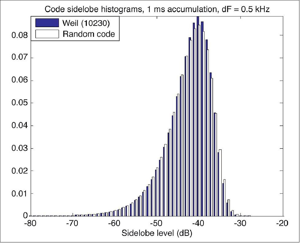
The first scenario is possible with the current version of the SBAS format. The other two options require some changes in the format of SBAS messages and international coordination. But the SDCM CPF is ready to operate in all of these modes.
Distribution. The main advantage of SBAS is its universal space channel to users. The SDCM orbit constellation will consist of three geostationary satellites from the multifunctional space relay system Luch (see Figure 49). Luch, which means “ray” or “beam” in Russian, will be used to relay communications between low Earth-orbiting spacecraft and ground facilities in Russia in a similar fashion to that of NASA’s Tracking and Data Relay Satellite System. The satellites will also include transponders for relaying SDCM signals from the CPF to users. The first satellite, Luch-5A, will be launched this year and will occupy an orbital slot at 16º west longitude. Luch-5B will be launched in 2012 to a slot at 95º east longitude. The full constellation will be deployed by 2014 with the launch of Luch-4 into a slot at 167º east longitude.
Wideband transponders (22 MHz) will be installed on board the Luch-5A and Luch-5B satellites. These transponders will transmit signals on a carrier frequency of 1575.42 MHz. As the SDCM service area is Russian territory, the main beam will be directed to the north with an angle of 7 degrees relative to the direction to the equator. The transmitted power will be 60 watts and will give a signal power level at the Earth’s surface roughly equal to that of GLONASS and GPS signals, about –158 dBW.
Parameter | Luch-5A | Luch-5B | Luch-5V |
Orbital position | 167ºE | 95ºE | 16ºW |
PRN (Pseudo Random Noise) | 140 | 125 | 141 |
Eccentricity | 0 | 0 | 0 |
Inclination | 0 | 0 | 0 |
Radius (Geostationary Orbit) | 42,164 km | 42,164 km | 42,164 km |
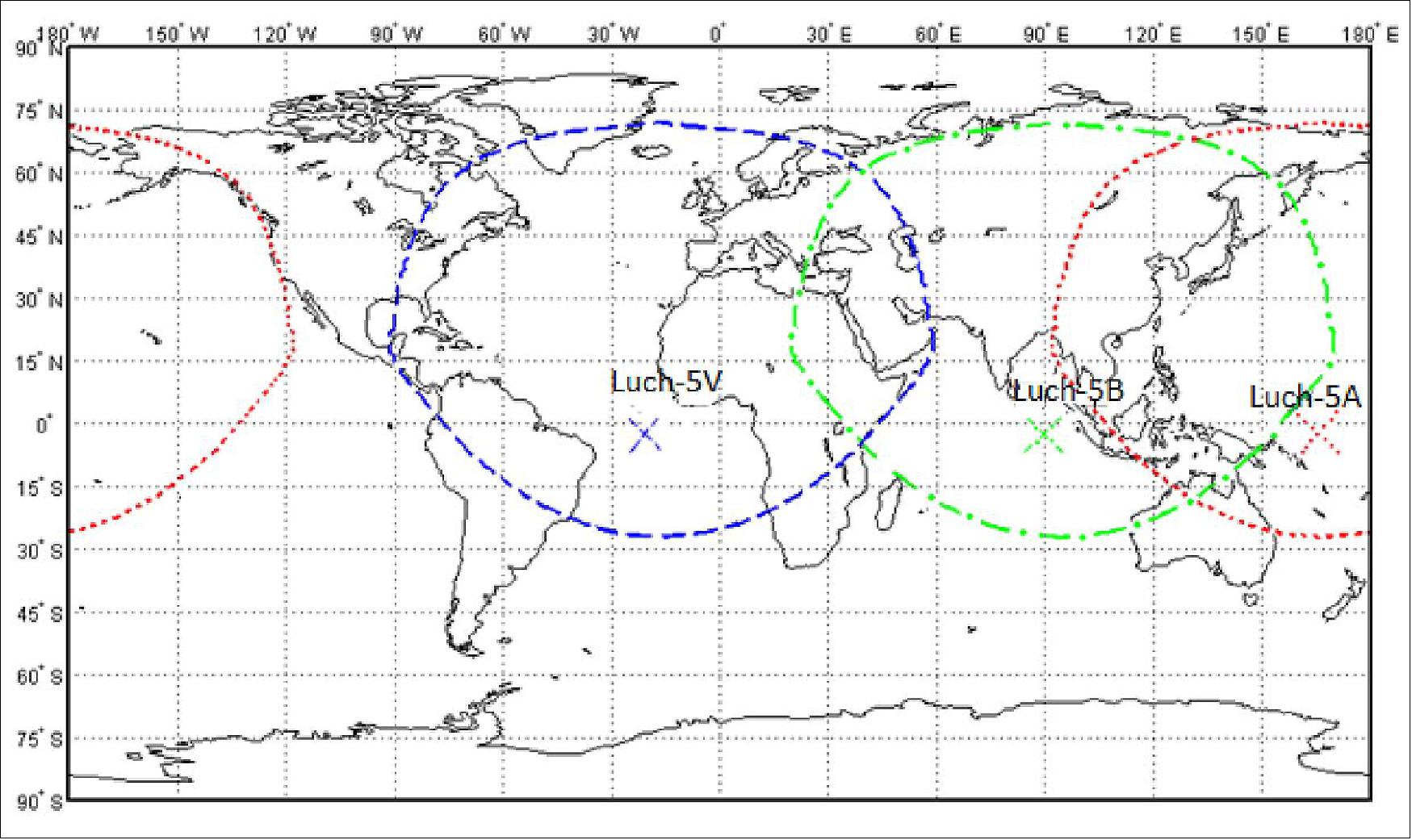
SDCM will also provide service through the Internet. A system website (www.sdcm.ru) already gives users information about real-time and a posteriori GLONASS and GPS monitoring (Figure 51). An SDCM data-broadcasting ground system has been developed and is being tested now. It will help to verify SDCM data before the Luch satellites are launched. SDCM SBAS messages will be transmitted through the Internet in real time using the SISNeT (Signal in Space through the Internet) approach. The SISNeT protocol was developed for relaying EGNOS messages over the Internet.
A set of experiments was carried out to evaluate SDCM performance. In one experiment, 130 hours of raw pseudorange data was processed to generate the results shown in Figure 52. The upper plot shows the positioning results of a stand-alone receiver working only with the GLONASS and GPS signals. The lower plot presents results of GLONASS/GPS/SDCM navigation. It is clear that the SDCM ephemeris and clock corrections improve user accuracy by more than a factor of two.
However, precise point positioning (PPP) technology, based on post-processing dual-frequency carrier-phase measurements with precise satellite ephemeris and clock data, expands the areas of practical use of satellite positioning without complex user ground infrastructure of reference stations and wireless communication channels. Studies have already demonstrated that decimeter-level PPP is possible using GLONASS data or GLONASS data in combination with GPS data. Tests are under way to deliver the precise satellite ephemeris and clock data over the Internet to allow real-time PPP. We can envisage that some time in the future, the ephemeris and clock data could be provided to users in real time using satellite signals.
SDCM interface definition (Ref. 38)
Figure 1 shows the General Interface from Space Segment(of GLONASS, SDCM and GPS systems)to the NUE (Navigation User Equipment). It is formed by the L1 radio signals of SDCM and opened GLONASS and GPS radio signals of L1, L2, L3 and L5 frequency bands.
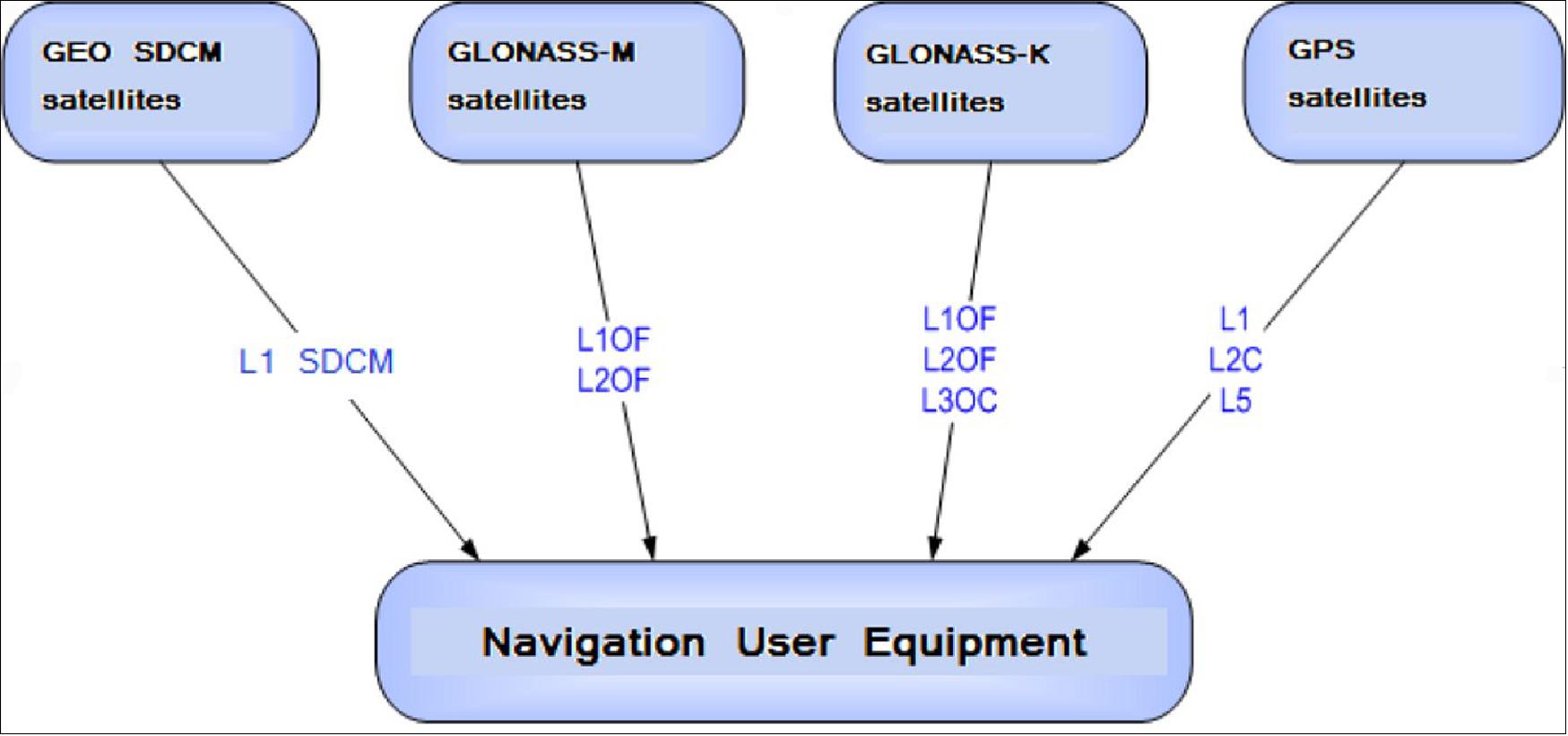
The GLONASS constellation includes GLONASS-M and GLONASS-K satellites. The GLONASS-M satellites radiate opened navigation radiosignals with frequency division (OF)in two frequency bands:L1 and L2.Satellites located in opposite points of the same orbit plane (antipodal), can transmit navigation radiosignals on equal carrier frequencies.
The GLONASS-K satellites of the first phase radiate L3OC opened radiosignals in the L3 frequency band, besides L1OF and L2OF.
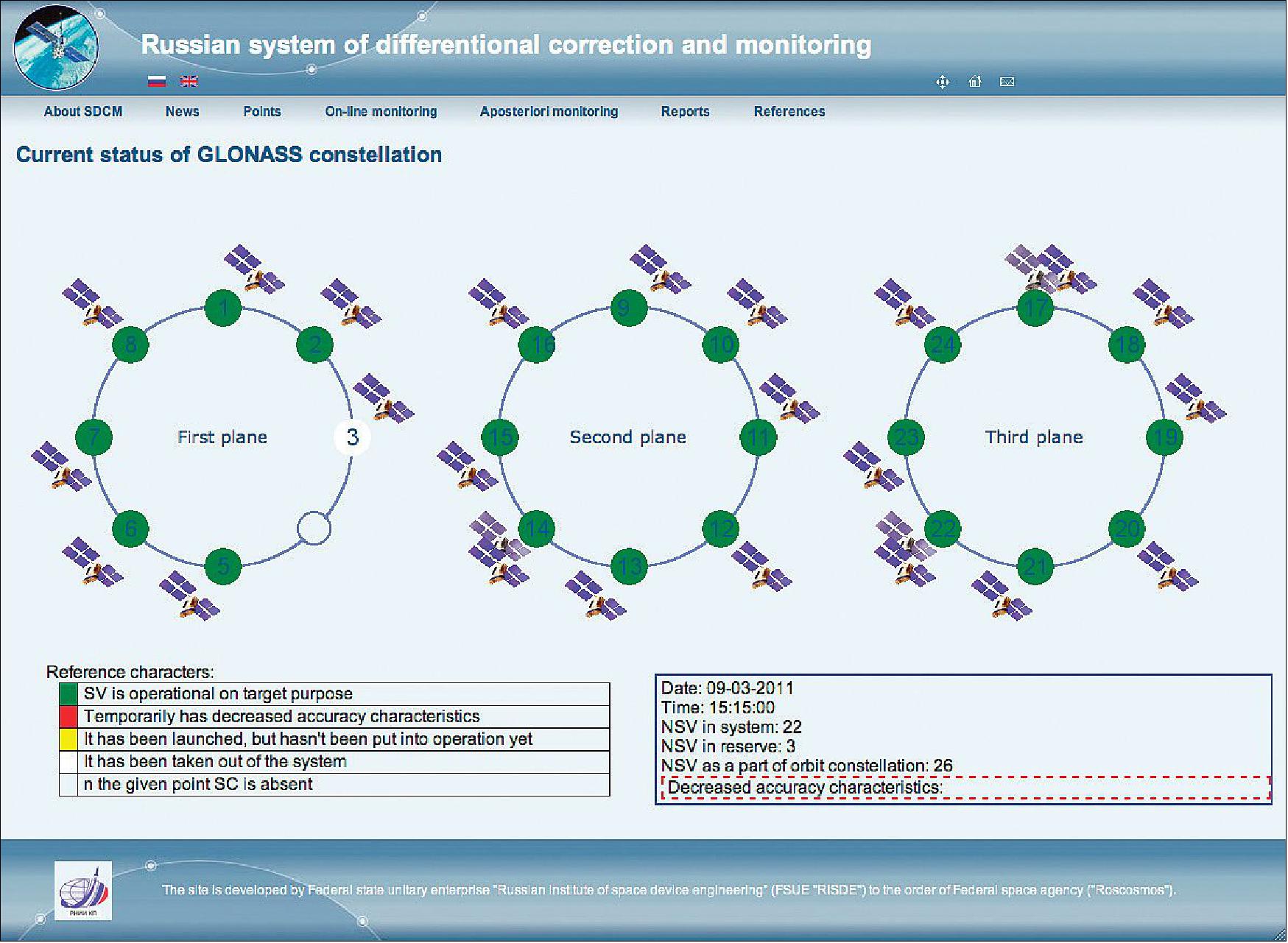
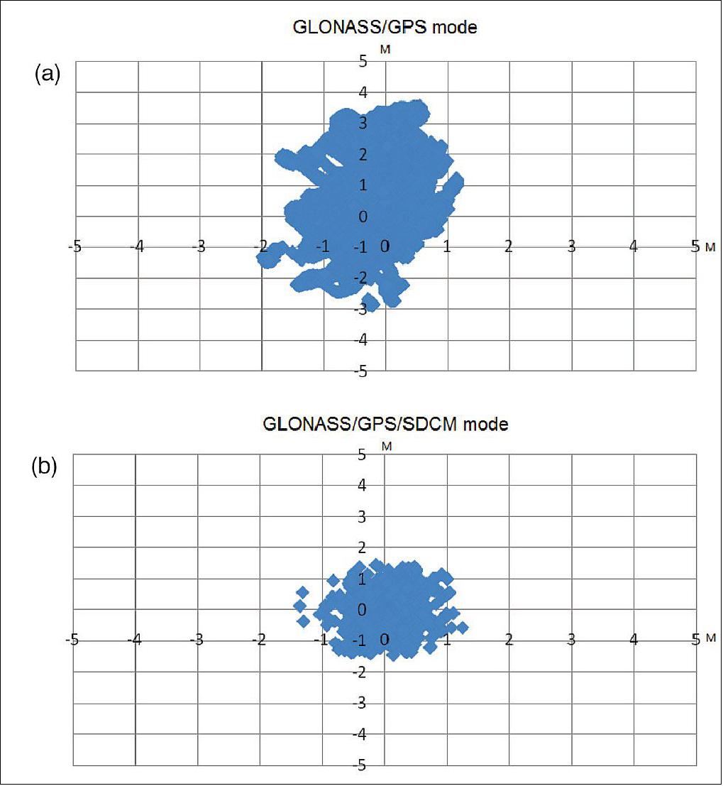
Future SDCM Satellites. The first SDCM satellites will provide service over the main part of Russia, excluding northern regions. To cover those regions, the SDCM orbit constellation could be enlarged using satellites in circular, inclined geosynchronous orbit (GSO); inclined, elliptical geosynchronous orbit (IGSO); or Molniya-type highly elliptical orbit (HEO) with an orbital period of precisely one-half of a sidereal day.
A comparative availability analysis for satellites with different orbits shows that using four GSO/IGSO/HEO satellites in two planes allows a user anywhere in Russia to continuously receive a signal from two satellites with a minimum elevation angle of 5 degrees. If the elevation mask angle is 30 degrees, availability will fall to 0.9 for IGSO satellites and 0.8 for HEO satellites. An orbit constellation of GSO satellites provides an availability of 0.8 and 0.3 for 5-and 30-degree mask angles, respectively.
It is important to point out that the development of satellite orbit and clock prediction technology allows us to consider the possibility of using GSO, IGSO, or HEO satellites for ranging signal broadcasting. In that case, the navigation message could include precise ephemerides and clock data for all GNSS satellites to provide the data for a PPP service as mentioned earlier.
BDSBAS (BeiDou Satellite Based Augmentation System) of China
The BeiDou Navigation Satellite System (BDS) has been built and developed in accordance with the "three-step" strategy. BDS-1 construction was started from 1994 and put into use in 2000. It adopted an active positioning scheme to provide Chinese users with positioning, timing, wide-area differential and short message communication services. BDS-2 construction was started from 2004 and put into use in 2012. Besides being technically compatible with BDS-1, BDS-2 also added a passive positioning scheme, to provide users in the Asia-Pacific region with positioning, velocity measurement, timing and short message communication services. BDS-3 construction was started from 2009. On the basis of BDS-2, BDS-3 further improves services performance and expands services functions, with the successful launch of 30 constellation satellites. It is planned to fully complete the BDS-3 by 2020, and to provide global users with high-quality services including navigation, positioning and data communication. 39)
As one of the core Global Navigation Satellite Systems (GNSS) providers, the BeiDou Navigation Satellite System (“BDS”) has been developed steadily following a three-step strategy. BDS has been providing global services since the end of 2018. By around 2020, the BDS-3 system will be entirely completed to provide global users with free, open and high-quality navigation, positioning, timing, short message communication and other services. A more ubiquitous, integrated and intelligent positioning, navigation, timing system will be built before 2035. 40)
In 2019, BDS has progressed with regard to aspects of system construction, integrated applications and international development.
System Construction
Accelerating Satellite Deployment. From January to November 2019, three BDS-3 satellites in inclined geosynchronous satellite orbit (IGSO) and four satellites in medium Earth orbit (MEO) were launched, and one IGSO satellite has completed in-orbit tests, to further improve the global system constellation.
The last two MEO satellites are planned to be launched by the end of 2019, marking the completion of the BDS core global constellation deployment. By June 2020, another two GEO satellites will be launched, and the full deployment of the BDS-3 system will be completed.
Ground System Construction. In 2019, 12 new ground operation and control stations (including one uplink station and 11 class-II monitoring stations) have been built, to complete the satellite-ground joint debug and integration tests, and the overall operation of the system is stable.
By the end of October 2019, 34 BDS satellites are operating in orbit to provide services to global users, including 15 BDS-2 satellites and 19 BDS-3 satellites.
Improving Service Performance
Key Service Areas. In May 2019, the last BDS-2 backup satellite was launched to further improve the performance in the key service areas of the BDS-2 system. As the BDS-3 satellites go into operation, the accuracy and availability of the BDS B1I and B3I signals, in the BDS-2service area, has been improved by about 30% and 5% respectively, compared with that of solely relying on the BDS-2 system.
Global Service Areas. The BDS B1I and B3I service areas have been expanded from the Asia Pacific region to the world, and the accuracy and availability have been further improved. With the condition of PDOP ≤ 6 (Position Dilution of Precision), the availability is better than 99% in most regions all over the world (in parts of the United States, better than 97%). In the global area, the mean value of the actual measured positioning accuracy is about 3.6m horizontally and 6.6 m vertically, velocity measurement accuracy is about 0.05 m/s, and timing accuracy is about 9.8 nanoseconds (95% confidence). So far, the BDS-3 new signals, B1C and B2a, have possessed service capacity worldwide. The system availability is better than 87%, in the condition of PDOP ≤ 6. The mean value of the actual measured positioning accuracy is about 2.4m horizontally and 4.3m vertically, velocity measurement accuracy is about 0.06 m/s and timing accuracy is about 19.9 nanoseconds (95% confidence).
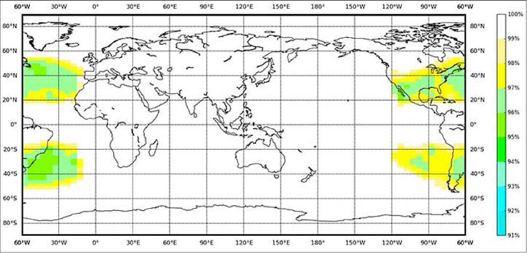
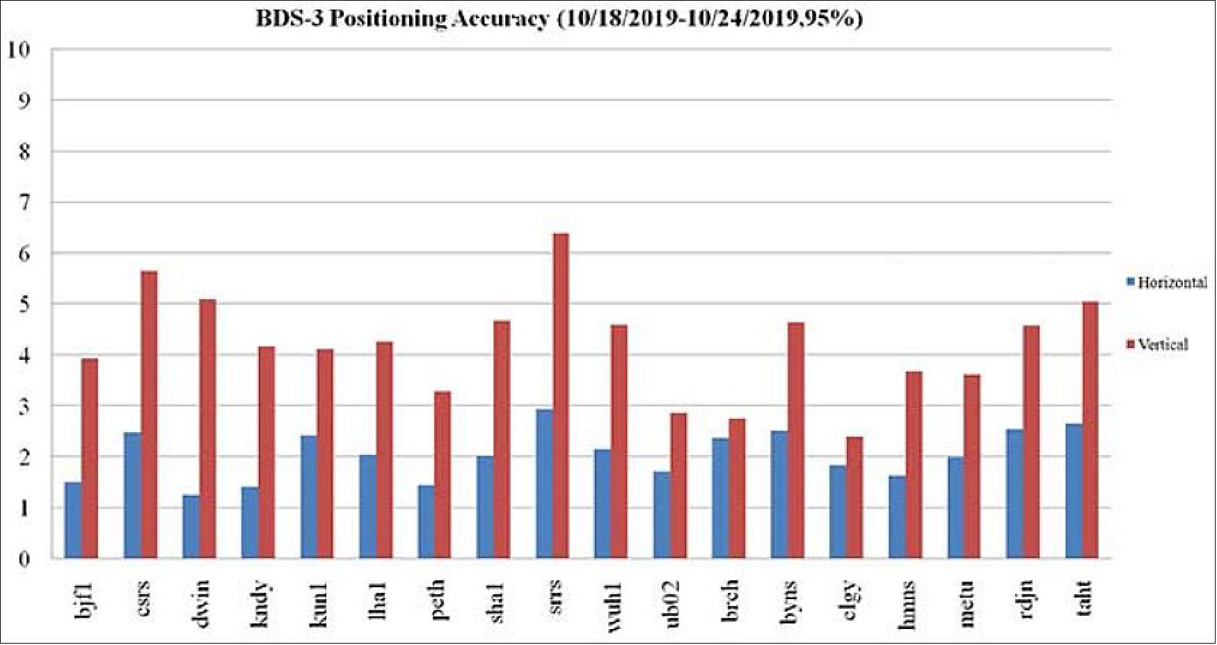
Building of the Featured Capacity. The BDS/GNSS ground based augmentation system has been providing basic services. It consists of 155 framework reference stations and nearly 2,200 regional stations in China. The system has carried out high-precision applications in many fields, such as surveying and mapping, land resources, earthquake, transportation and meteorology. Its basic services include real-time positioning at the meter, decimeter and centimeter level, as well as precise post-processing positioning at the millimeter level.
The BeiDou Satellite-Based Augmentation System (BDSBAS) is being developed in accordance with International Civil Aviation Organization (ICAO) standards to provide navigation services with superior accuracy and integrity. In 2019, the first GEO satellite with the BDSBAS payload has been tested in orbit and the satellite is in good condition.
Integrated Applications
As the system construction accelerates, BDS is also making great efforts to strengthen the development of the fundamental products and applications in various fields. The integrated applications adopt the “BDS+” model to stimulate the growth of satellite navigation industry.
Fundamental Products. At present, the fundamental BDS products have been used in such areas as mass market applications, of which the performance has reached or is close-to the world-class level. The development of full-frequency integrated high-precision chips is near its completion, and the performance of the BDS chips will improve further. By the end of 2019, BDS navigation chips, modules and antennas have been exported to more than 100 countries and regions. In 2018, the domestic output value was more than RMB 300 billion (US$43 billion), in which the BDS contribution exceeds 80%.
Industrial Applications. BDS has been widely used in various fields — communication and transportation, public security, agriculture, forestry, animal husbandry and fishery, hydrological monitoring, meteorological forecast, time synchronization, power dispatching, disaster prevention and mitigation — generating significant economic and social benefits. In the field of transportation, by September 2019, more than 6.47 million road operating vehicles and 42,300 postal and express delivery vehicles in China are using BDS, and the world’s largest dynamic supervision system of operating vehicles has been formed, which effectively improved management efficiency and road transportation safety.
In agriculture, a BDS-based automatic driving system has been equipped on more than 20,000 sets of agricultural machinery and equipment, saving 50% of the labor cost. The BDS-based agricultural machinery operation supervision platform and the IoT platform has been serving 10 million units of agricultural machinery equipment, greatly improving management and operational efficiency.
In disaster prevention and mitigation, a tri-level platform covering the national ministry, the provinces, and cities and counties has been built to offer six-tier application services, with more than 45,000 terminals using BDS. The BDS/GNSS high-precision technologies have been applied in the field of geological disaster monitoring, while the landslides in Gansu province have been successfully forecast repeatedly, with time accuracy at the second level and deformation accuracy at the millimeter level.
Mass Market Applications. The BDS-based navigation and positioning services have been adopted by various enterprises in the fields of e-commerce, smart mobile terminal manufacture, location-based services (LBS), the sharing economy and the mass market, thereby changing people’s production and life style profoundly. Mainstream manufacturers in China and around the world have introduced BDS-compatible chips that integrate communication and navigation functions.
According to Chinese market statistics, in the third quarter of 2019, 151 types of mobile phones applying for license have positioning functions, among which 110 models support BDS. Using BDS/GNSS ground based augmentation stations, the spatial-temporal services including centimeter-level positioning, millimeter-level perception and nanometer-level timing services can be provided, while the accelerated positioning services cover 220 countries and regions with more than 390 million global users.
International Development
Bilateral Cooperation. BDS continues to carry out bilateral cooperation with other navigation satellite systems, to promote compatibility and joint applications. China and the United States have set up joint working groups in areas such as compatibility and interoperability, augmentation systems and civil services to continuously develop cooperation and exchanges.
China and the EU set up a technical working group on the compatibility and interoperability between the BDS and Galileo systems to carry out coordination, exchanges and cooperation, under the framework of the China-EU space cooperation dialog and the International Telecommunications Union (ITU). The agreement between the Government of the People’s Republic of China and the Government of the Russian Federation on Cooperation in the Field of the Use of BeiDou and GLONASS for Peaceful Purposes has come into effect.
In August 2019, China and the Russian Federation held their sixth bilateral meeting in Kazan, Russia, signed the site survey certificate of GNSS monitoring stations, and achieved many cooperation results. In addition, the bilateral cooperation with Iraq, Tunisia and Saudi Arabia has also been steadily promoted.
Multilateral Cooperation. During the 62nd session of the Committee on the Peaceful Uses of Outer Space (COPUOS) in June 2019, an exhibition on ancient Chinese navigation technologies was held at the Vienna International Center with the theme “From Compass to BeiDou,” which vividly demonstrated China’s brilliant achievements in timing, mapping, cartography and navigation science and technology. In April and October, 2019, the second China-Arab States BDS Cooperation Forum and China-Central Asia BDS cooperation forum were held in Tunis and Nanning, China, respectively, to promote the BDS to serve the Arab region and Central Asian countries.
The BDS Overseas Applications Were Steadily Promoted. With BDS high-precision products being exported, BDS has been widely used in different regions and fields, such as land registration, precision agriculture, warehouse logistics in ASEAN countries, construction in Western Asia, airport timing and piling at seas in South Asia, electric power inspection in Eastern Europe, and land survey in African countries. As BDS-3 system continues to improve construction, it will provide quality services for more people in a wider area.
Ratification of BDS by International Standards. BDS has made a clear schedule to be ratified by the ICAO standards in 2020. It has formulated 26 standards in the field of international mobile communication based on the BDS B1I signal, and other standards based on the B1C and B2a signals are being developed. A receiver positioning result output protocol (NMEA0183) and a receiver data exchange format (RINEX 3.04) supporting BDS are to be released. Technical parameters and index information of BDS search and rescue (SAR) payloads are included in relevant COSPAS-SARSAT documents, and the development and in-orbit test of the first batch of SAR payload has been completed. The first BDS standard in the International Electrotechnical Commission (IEC) has been developed and approved and is expected to be released in June 2020.
Future Plans
After BDS achieves global service capabilities by 2020, it will further improve global navigation, positioning, timing and regional short-message communication services, and finalize global short-message communication, international search and rescue, satellite-based augmentation, precise point positioning, and other service capabilities. China’s BDS will contribute Chinese solutions to the world, and give full play of its role, with a renewed attitude, stronger capabilities and better services, to serve the world and benefit humankind.
Development Status
• December 2019: The BDS development aims to build a world-class navigation satellite system to meet the needs of the country’s national security as well as economic and social development; to provide continuous, stable and reliable services for global users; to develop BDS-related industries to support China’s economic and social development and to improve people’s living standards; and to enhance international cooperation to share the development fruits in the field of satellite navigation to improve the comprehensive application efficiency of global satellite navigation systems. 41)
Main architecture: BDS is mainly comprised of three segments: A space segment, a ground segment and a user segment.
- The space segment: The BDS space segment consists of a number of satellites located in the Geostationary Earth Orbit (GEO), Inclined Geo-Synchronous Orbit (IGSO) and Medium Earth Orbit (MEO).
- The ground segment: The BDS ground segment consists of various ground stations, including master control stations, time synchronization/uplink stations, monitoring stations, as well as operation and management facilities of the intersatellite link.
- The user segment: The BDS user segment consists of various kinds of the BDS products, systems, and services as well as those compatible with other navigation systems, including basic products such as chips, modules and antennae, terminals, application systems and application services.
The BDS development follows a model of developing regional service capacities fast, then gradually extending the services globally. This practice has blazed a path for building a satellite navigation system with Chinese characteristics, and enriched the development models for navigation satellite systems worldwide.
BDS possesses the following characteristics: Firstly, its space segment is a hybrid constellation consisting of satellites in three types of orbits. In comparison with other navigation satellite systems, BDS operates more satellites in high orbits to offer better anti-shielding capabilities, which is particularly observable in terms of performance in the low-latitude areas. Secondly, BDS provides multi-frequency navigation signals, and is able to improve the service accuracy by using combined signals. Third, BDS integrates navigation and communication function, and possesses multiple service capabilities, namely, positioning, navigation and timing, short message communication, international search and rescue, satellite-based augmentation, ground augmentation and precise point positioning, etc.
By the end of 2019, 24 BDS-3 MEO satellites have been launched, marking the complete deployment of the core BDS-3 constellation to comprehensively upgrade the system service performance and users’ experience, while the BDS services are available worldwide.
Service Performances: The BDS positioning, navigation and timing service performance standards are as follows:
- System service coverage: global
- Positioning accuracy: 10 meters horizontally, 10 meters vertically (95%)
- Velocity measurement accuracy: 0.2 m/s (95%)
- Timing accuracy: 20 nanoseconds (95%)
- System service availability: better than 95%.
In the Asia-Pacific region, the positioning accuracies are 5 meters horizontally and 5 meters vertically (95%).
Future development: By the end of June 2020, another 2 BDS-3 GEO satellites will be launched. In the future, BDS will continue to improve service performance, expand service functions, and guarantee continuous and stable operation, to further improve global positioning, navigation and timing, regional short message communication, and ground augmentation service capabilities, and to provide the satellite-based augmentation, precise point positioning, global short message communication, and international search and rescue services, etc. BDS is planned to provide following services in 2020.
Service Types | Signal(s)/Band(s) | Broadcast Satellites | |
| Positioning, Navigation and Timing | B1I, B3I, | 3GEO+3IGSO+24MEO |
Global Short Message | Uplink: L | Uplink: 14MEO | |
International SAR (Search And Rescue) | Uplink: UHF | Uplink: 6MEO | |
| Satellite-Based Augmentation System | BDSBAS-B1C, BDSBAS B2a | 3GEO |
Ground Augmentation System (GAS) | 2G, 3G, 4G, 5G | Mobile communication networks, Internet | |
Precise Point Positioning (PPP) | PPP-B2b | 3GEO | |
Regional Short Message Communication | Uplink: L-band | 3GEO | |
- Positioning, navigation and timing services. These services are available for global users. The signal-in-space (SIS) accuracy is superior to 0.5 m. The global positioning accuracy is better than 10 meters, the velocity measurement accuracy is better than 0.2 m/s, the timing accuracy is better than 20 nanoseconds. The overall performance will be greatly improved in the Asia-Pacific region, with the positioning accuracy better than 5 meters, the velocity measurement accuracy better than 0.1 m/s, and the timing accuracy better than 10 ns.
- Short message communication services. As for short message communication services in China and surrounding areas, the service capacity will be increased to 10 million times per hour and the receiver transmit power will be reduced to 1-3 W, with capability as 1,000 Chinese characters per message (14,000 bytes). As for global short message communication services, the service capability is 40 Chinese characters per message (560 bytes).
- SBAS (Satellite-Based Augmentation Services). The satellite-based augmentation services will be provided to users in China and surrounding areas, in accordance with the standards of the International Civil Aviation Organization (ICAO), supporting single frequency and Dual Frequency Multi-Constellation (DFMC) formats, and meeting the ICAO performance requirements.
- The BeiDou ground augmentation system. BDS utilizes mobile communication networks or the Internet to provide users within the coverage area of reference station network, with high-precision positioning services at the meter, decimeter, centimeter and millimeter levels.
- International SAR (Search and Rescue) services. The international search and rescue services will be provided to global users. This function will be offered by a global MEOSAR system jointly supported by BDS and other navigation satellite systems in accordance with the COSPAS-SARSAT standards. Distress alert services based on return-links will also be provided, which will greatly enhance the efficiency and capability of search and rescue services.
- PPP (Precise Point Positioning) service. The PPP service will serve users in China and surrounding areas, with the dynamic precise position service accuracy at decimeter level and static precise position service accuracy at centimeter level.
• December 20, 2018: From January 17 to 19, 2018, the 33rd Meeting of the SBAS IWG was held in Madrid, Spain. More than 50 representatives from different satellite navigation authorities of China, the United States, the European Union, Russia, Japan, South Korea, Africa, Australia and related international organizations attended the meeting. Experts from China Satellite Navigation Office, Civil Aviation Administration of China, the 20th Institute of China Electronics Technology Group Corporation, Tsinghua University, Beihang University, and Beijing UniStrong Science and Technology Co., Ltd. formed the Chinese delegation to the conference. 42)
This SBAS IWG meeting discussed the SBAS standards, the coordination work of the SBAS modernization plan, progress of the SBAS technology research and development, the global SBAS status report, and exchanges among technical groups. Representatives from the Federal Aviation Administration of the United States, European Space Agency and Eurocontrol, Japan Civil Aviation Administration, Korea Aerospace Research Institute, Agency for Aerial Navigation Safety in Africa and Madagascar (ASECNA), and Geoscience Australia presented reports on the progress of satellite navigation systems and satellite-based augmentation systems, such as GPS/WAAS in the United States, Galileo/EGNOS in Europe, MSAS/QZSS in Japan, KASS in Korea , SBAS-ASECNA in Africa, and the Australian SBAS test system. All the delegates also discussed several documents including SBAS dual-frequency multi-constellation (DFMC) standards, civil aviation/maritime region applications, minimum operating standards (MOPS), and the Concept of Operations (CONOPS).
The Chinese representative participated in various discussions in the conference. Dr. Jun Shen, Chief Scientist of Beijing UniStrong Science and Technology Co. Ltd, presented a report on the development of the BeiDou Satellite Navigation System (BDS) and the BeiDou Satellite-based Augmentation System (BDSBAS) on behalf of the Chinese delegation. He introduced the progress, system status, global system construction and subsequent planning of BDS and BDSBAS, as well as the progress of the BDSBAS PRN (Pseudo Random Noise) number assignment process, Service Provider Identification Number (SPIN), and system standard time identification and the integrated test of the first BDSBAS GEO satellite. Chinese experts conducted detailed exchanges with experts from various parties on issues such as the progress of BDSBAS ground station construction, single-frequency enhanced service design, enhanced signal ranging capabilities, and improved signal generation methods.
At the first meeting of the Technical Sub-working Group, Professor Mingquan Lu of Tsinghua University presented the technical report on the new BDS civil signals B1C and B2a. He detailed the design, performance characteristics and receiving methods of the BDS signals, as well as their superior performance. The BDS Signal Interface Control Documents (ICD) were provided at the conference, which caused great interest among technical experts from various countries.
Based on the major breakthroughs in 2017, such as the GEO satellite PRN number assignment SPIN and system standard time identification of BDSBAS, the BDSBAS international cooperation team further consolidated the position of BDSBAS as a SBAS service provider. Those breakthroughs also enhanced the confidence of international users in using BDS and BDSBAS in the future.
KASS (Korean Augmentation Satellite System)
The government of Korea established the mid and long-term plan of the RNSS (Regional National Space Development) in 2013. The Ministry of Science and ICT finalized the third Space Development Promotion Plan at National Space Committee on 5 February 2018 called KPS (Korea Positioning System). The RNSS concept is complementary to other GNSS systems. 43) 44)
Total 7+ satellites constellation
- GEO satellites 3
- EIGSO (Elliptically Inclined Geosynchronous Orbit) satellite
Development Status
• June 2019: System Development of KASS (Korean SBAS). The goal is to develop a SBAS in compliance with ICAO 10 performance requirements. 45)
Overview: KASS development during 8 years in 5 phases (2014-2022)
- Phase A (Oct. 2014-Jun. 2015): System Definition
- Phase B (Jul. 2015-Mar. 2017): System Design
- Phase C (Apr. 2017-Mar. 2019): Critical Design
- Phase D (Apr. 2019-Jun. 2020): Integration and Verification
- Phase E (Jul. 2020-Oct. 2022): Initial Operation and Approval Process
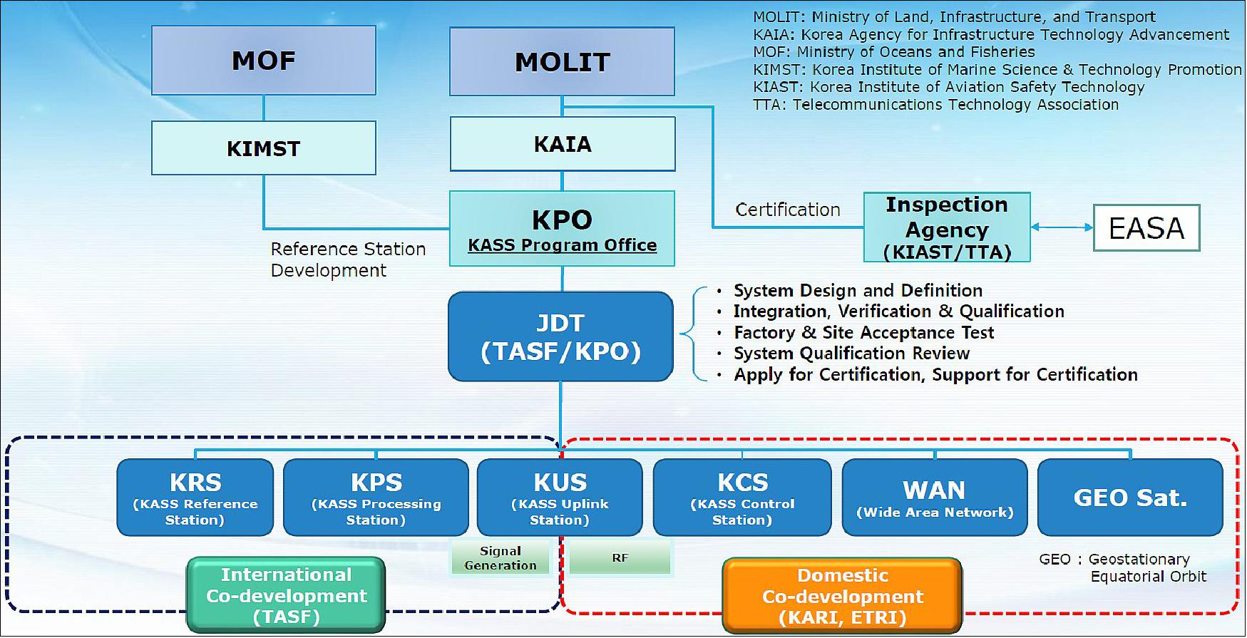
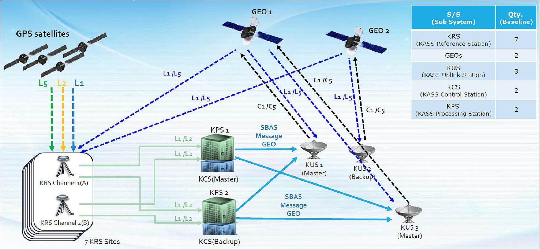
• November 30, 2016: Technology developed as part of Europe’s satellite navigation-augmenting EGNOS system has been sold to South Korea to serve its national equivalent system. 46)
Thales Alenia Space has signed a contract with South Korea’s space agency KARI (Korea Aerospace Research Institute), to supply ground infrastructure for KASS (Korea Augmentation Satellite System) on behalf of the South Korean Ministry of Land, Infrastructure and Transport (MOLIT).
The infrastructure is derived from that developed by Thales Alenia Space under contract to ESA and in its role as prime contractor for EGNOS, which has been operational since 2009 for general use and since 2011 for ‘safety of life’ applications, including aviation.
Designed by ESA and being exploited by Europe’s Global Navigation Satellite System Agency, EGNOS improves the precision of US GPS signals over most European territory, while also providing continuous and reliable updates on the ‘integrity’ of these GPS signals.
A network of 40 ground monitoring stations throughout Europe performs an independent measurement of GPS signals, so that corrections can be calculated and then passed to users immediately via a number of geostationary satellites. The result is that the EGNOS-augmented signals are guaranteed to meet the extremely high performance standards set out by the International Civil Aviation Organisation standard, adapted for Europe by Eurocontrol, the European Organisation for the Safety of Air Navigation.
An SBAS (Satellite Based Augmentation System), such as EGNOS and the US WAAS (Wide Area Augmentation System), operate by ensuring the integrity and positioning accuracy of GPS, as well as, in the decade to come, the European Galileo, Russian Glonass and Chinese Beidou systems.
KASS is projected to be the ninth regional SBAS in service when it becomes operational at the end of the decade. The various systems are designed to be fully interoperable, ensuring air traffic safety as aircraft move between different zones, and jointly providing an almost worldwide service.
• October 25, 2016: South Korea and France’s Thales Group will jointly develop an advanced SBAS (Satellite-Based Augmentation System) for GPS and other GNSS services by 2021. 47)
KARI (Korea Aerospace Research Institute) will sign a $40 million deal with Thales Group on Oct. 26, according to the Ministry of Land, Infrastructure and Transport.
The new SBAS, dubbed KASS (Korean Augmentation Satellite System), especially will help reduce errors in aviation GPS, which currently occur at a rate of one in 5 million and by up to 16 meters horizontally and 20 meters vertically.
“By reducing the error and providing more accurate location of aircraft by using satellites, the SBAS is expected to help set the shortest air route possible while also helping reduce the cost of fuel for flights and thus expanding their capacities,” the ministry said in a press release.
A separate agreement will be signed with the European Aviation Safety Agency to jointly verify the new GPS augmentation system following its development.
KASS will rely on EGNOS (European Geostationary Navigation Overlay System) developed by Thales Alenia Space as prime contractor for the European Commission, with the European Space Agency (ESA) as contracting authority. The EGNOS system is operating in Europe since 2009 for Safety of Life services.
South Korea will initially be using KASS to provide aeronautical applications, including Safety of Life services so that it can be used during different flight phases, especially landings. It will eventually extend these services to other applications, including maritime, road and rail.
“Our first export success with this sophisticated and powerful navigation system is the upshot of Thales Alenia Space’s involvement with Europe’s satnav projects since the outset, in 1996,” said Jean Loïc Galle, president and CEO of Thales Alenia Space. “We are drawing on 20 years of experience to help the Korean space agency, and allow government bodies in the country to develop applications that will improve its people’s comfort and safety for all types of transportation.”
Thales Alenia Space’s contract with KARI concerns the supply of the ground infrastructure. It will initially operate via a relay provided by an existing geostationary satellite, and it will be interoperable with other SBAS worldwide, which guarantee air traffic safety when planes move between different zones. KARI and Thales Alenia Space will be applying an approach based on partnership, which means that an integrated French-Korean team will be in charge of the project.
SPAN (Southern Positioning Augmentation Network)
• March 3, 2020: SPAN is a regional SBAS program in development which will cover Australia and New Zealand. Australia and New Zealand are a step closer to improving the accuracy of global positioning signals across the Australasian region. 48)
As announced at the Australia New Zealand Leaders’ Forum last week, Australia and New Zealand have agreed to jointly fund the first SBAS (Satellite-Based Augmentation System) in the Southern Hemisphere. The new SPAN (Southern Positioning Augmentation Network) will be led by Geoscience Australia and Land Information New Zealand (LINZ) under the Australia New Zealand Science, Research and Innovation Cooperation Agreement.
Geoscience Australia CEO Dr James Johnson said the Southern Positioning Augmentation Network will improve the accuracy of positioning from 5-10 m to 10 cm without the need for mobile or internet coverage.
“Australia and New Zealand are working together to bring this world-leading technology to our region, joining countries such as the United States, Europe, Russia, India and Japan, which have all successfully invested in an SBAS capability,” Dr Johnson said.
“We know through an 18-month trial of SBAS in Australia and New Zealand that decimeter level accuracy will significantly improve productivity and safety in our modern world. The benefits of SBAS were recognized in an independent report by Ernst and Young (EY) in 2019, which showed improved positioning could provide more than seven billion dollars in economic benefits to Australia and New Zealand.”
LINZ Chief Executive Ms Gaye Searancke said Geoscience Australia and LINZ have a strong and productive working relationship on mutual interests. “Geoscience Australia and LINZ worked together on the trial of SBAS and our relationship has continued to grow across the Tasman,” Ms Searancke said.
“This means we are confident that the Southern Positioning Augmentation Network will provide economic efficiencies and safety improvements to sectors important to both our nations, such as agriculture, construction, and transport. For example, improved precise positioning will make regional aviation safer and more efficient, which is essential to both our rugged countries. Our partnership will also provide a more informed region through better location-based data and mapping, shared marine data and information, and through Earth observations from space.”
• 2020: Our position on the globe is essential to everyday life. Position allows us to locate ourselves in the world and get to where we want to go. Satellite positioning technologies have enabled the precise navigation and positioning we rely on at the touch of a button, from smartphones to autonomous vehicles. This brings increased productivity, improved community safety and boosted innovation. The reported economic benefits of these technologies have the potential to generate upward of $73 billion of value to Australia by 2030. 49)
Global navigation satellite systems: To determine position, velocity and time we rely on GNSS (Global Navigation Satellite System) technology. Australia is one of few countries in the world with high visibility to four GNSS and two regional navigation satellite systems due to our geographical location. These include the United States' Global Positioning System (GPS), Russia's GLONASS, Japan's Quasi Zenith Satellite System (QZSS), the European Union's Galileo System, China's BeiDou Navigation Satellite System (BeiDou) and the Indian Regional Navigation Satellite System (IRNSS). Each system contains multiple satellites and can be used by land, sea and airborne users in all weather conditions, anywhere and anytime.
Geoscience Australia is working to ensure that accurate positioning information is widely available to the community through the Positioning Australia program. This is being delivered through two complementary projects: a national network of ground station infrastructure known as the National Positioning Infrastructure Capability (NPIC) and a system to deliver corrected positioning signals directly to you via satellite technology through an Australian Satellite-Based Augmentation System (SBAS). Together, these will provide more reliable positioning information, allowing for innovation and efficiency across a range of scenarios such as agriculture, transport, emergency management, mining, engineering and logistics.
Current technology typically allows for positioning within 5-10 m accuracy, but through this program, accuracy will be improved to within 3 cm in areas with mobile phone coverage and 10 cm everywhere else. This will deliver accurate, reliable and instantaneous positioning across Australia and its maritime zones.
A national positioning network: To maximize the value of GNSS, we’re establishing the necessary ground infrastructure to track, verify and optimize data for precise positioning across Australia. We’re building new ground stations and integrating existing stations so multiple GNSS signals can be received. To verify and correct the positioning signals for users, we’ll also establish a GNSS data analytics capability. This will ensure industry has access to software tools for positioning.
Coordination across government and industry is vital to maximize value from current and future positioning investment. The program will develop a national network through coordination of current infrastructure already installed across Australia by private industry, deferral, state, territory and local governments. This will reduce coverage gaps in regional and remote communities and avoid unnecessary duplication. Investing strategically in the location and capability of ground infrastructure will reduce national barriers to accurate and reliable positioning and create opportunities for business.
Enhancing positioning coverage: A Satellite-Based Augmentation System (SBAS) overcomes current gaps in mobile and radio communications and, when combined with our national infrastructure network, ensures that accurate positioning information can be received. SBAS augments and corrects GNSS signals to improve the accuracy of positioning data and makes it available across Australia and its maritime zones without the need for mobile phone or internet coverage.
This will see Australia and New Zealand join countries such as the United States, Europe, Russia, India and Japan, which have all invested in capability that delivers satellite-based corrections via an SBAS. It will also support the aviation, maritime and road transport sectors in meeting requirements for high-integrity positioning-guaranteed performance with meter level accuracy.
References
1) ”GNSS augmentation,” Wikipedia, URL: https://en.wikipedia.org/wiki/GNSS_augmentation
2) Achim Hornbostel, ”Propagation Problems in Satellite Navigation,” Proceedings of WFMN07 (Wave Propagation in Communication, Microwave Systems and Navigation), Chemnitz, Germany, 2007, URL:
xhttps://web.archive.org/web/20200806163219/https://monarch.qucosa.de/api/qucosa:18847/attachment/ATT-4/
3) ”Augmented satnav teams work together for safer flying,” ESA / Applications / Navigation, 05 March 2020, URL: http://www.esa.int/Applications/Navigation/Augmented_satnav_teams_work_together_for_safer_flying
4) ”The World of WAAS: Part 1,” ION Newsletter, Winter 2019, URL: https://www.ion.org/newsletter/upload/ION_Newsletter_WorldofWAAS_3_parts.pdf
5) ”Fact Sheet – Wide Area Augmentation System (WAAS),” FAA, 29 July 2013, URL: https://www.faa.gov/news/fact_sheets/news_story.cfm?newsId=14974
6) https://www.gps.gov/systems/augmentations/#cors
7) ”The Global Differential GPS System,” NASA, 2016, URL: http://www.gdgps.net/system-desc/network.html
8) Tim Schempp, ”WAAS Development Changes Since Commissioning,” GBAS/SBAS Implementation Workshop, Seoul, Republic of Korea, 3 – 5 June 2019, URL: https://www.icao.int/APAC/Meetings/2019%20GBASSBAS/1-4_WAAS_Development_Changes_Since_Commissioning_final%20(T%20Schemmp).pdf
9) ”Wide Area Augmentation System,” Raytheon Intelligence & Space, 22 September 2020, URL: https://www.raytheonintelligenceandspace.com/capabilities/products/WAAS
10) Greg Thompson, ”Wide Area Augmentation System (WAAS) –Program Overview,” 4 February 2020, URL: https://web.archive.org/web/20210319034357/https://www.faa.gov/about/office_org/headquarters_offices/ato/service_units/techops/navservices/gnss/library/briefings/media/WAAS_Program_Status_Update_Feb_2020.pdf
11) ”Raytheon upgrades WAAS with GEO 6 payload,” GPS World, 5 November 2019, URL: https://www.gpsworld.com/raytheon-upgrades-waas-with-geo-6-payload/
12) Carlos Rodriguez, ”Wide Area Augmentation System (WAAS) Update,” 16 August 2016, URL: https://www.icao.int/SAM/Documents/2016-PBNGNSS/12%20FAA%20SBAS%20Overview.pdf
13) Mary Ann Davis, ”WAAS Now Available in Canada and Mexico,” FAA SatNav News, Volume 32, November 2007, URL: https://web.archive.org/web/20200923002448/https://www.faa.gov/about/office_org/headquarters_offices/ato/service_units/techops/navservices/gnss/library/satnav/media/satnavnews_november2007.pdf
14) ”What is EGNOS?,” GSA, 2018, URL: https://www.gsa.europa.eu/egnos/what-egnos
15) ”EGNOS User Support,” GSA, 10 March 2020, URL: https://egnos-user-support.essp-sas.eu/new_egnos_ops/egnos-system/about-egnos
16) G. Gomelli, ”EGNOS Status 3 June 2019,” Thales Alenia Space, URL: https://www.icao.int/APAC/Meetings/2019%20GBASSBAS/1-5_EGNOS%20Status_final%20(G%20COMELLI).pdf
17) Ugo Celestino, ”EGNOS status, roadmap, extension to Euromed,” Joint ACAC/ICAO Workshop on GNSS, Rabat, 7-8 November 2017, URL: https://www.icao.int/MID/Documents/2017/ACAC-ICAO%20GNSS%20Workshop/EC%20Rabat%20EGNOS%20status%20%20roadmap%20ext_final.pdf
18) Javier Benedicto, ”Directions 2020: Galileo Moves Ahead,” GPS World, 14 December 2019, URL: https://www.gpsworld.com/directions-2020-galileo-moves-ahead/
19) ”EGNOS technology for Africa – ESA signs deal with ASECNA,” ESA Applications. 29 June 2022, URL: https://www.esa.int/Applications/Navigation/EGNOS_technology_for_Africa_ESA_signs_deal_with_ASECNA
20) ”Ten years of safer skies with Europe’s other satnav system,” ESA / Applications / Navigation, 17 March 2021, URL: https://www.esa.int/Applications/Navigation/Ten_years_of_safer_skies_with_Europe_s_other_satnav_system
21) ”Eutelsat entrusted once again by the European GNSS Agency (GSA) to host EGNOS GEO-04 payload,” GSA Press Release, 9 February 2021, URL: https://www.gsa.europa.eu/sites/default/files/content/press_releases/egnos_2021_gsa.pdf
22) ”EGNOS continues its expansion into European airports towards all RNP approaches in 2024,” Egnos user support, 8 October 2020, URL: https://egnos-user-support.essp-sas.eu/new_egnos_ops/news-events/news/egnos-continues-its-expansion-european-airports-towards-all-rnp-approaches-2024
23) ”New Multi-GNSS Reference Station,” ESA / Enabling & Support / Space Engineering & Technology, 12 June 2020, URL: http://www.esa.int/Enabling_Support/Space_Engineering_Technology/New_Multi-GNSS_Reference_Station
24) ”Space synergies for food security,” GSA, 10 June 2020, URL: https://www.gsa.europa.eu/newsroom/news/space-synergies-food-security
25) ”ESA’s Navigation Directorate supporting EGNOS and Galileo services continuity,” ESA / Applications / Navigation, 30 March 2020, URL: http://www.esa.int/Applications/Navigation/ESA_s_Navigation_Directorate_supporting_EGNOS_and_Galileo_services_continuity
26) ”Third and last GEO Swap successfully completed!,” ESSP, 27 March 2020, URL: https://egnos-user-support.essp-sas.eu/new_egnos_ops/news-events/news/third-and-last-geo-swap-successfully-completed
27) ”Thales Alenia Space wins new EGNOS contract from European Space Agency,” TAS, 5 December 2019, URL: https://www.thalesgroup.com/en/worldwide/space/press-release/thales-alenia-space-wins-new-egnos-contract-european-space-agency
28) ”Airbus selected by ESA for EGNOS V3 program,” 26 January 2018, URL: https://web.archive.org/web/20210507215342/https://www.airbus.com/newsroom/press-releases/en/2018/01/airbus-selected-by-esa-for-egnos-v3-programme.html
29) ”EGNOS: great for regional aviation,” Satellite Navigation, March/ April 2017, URL: https://egnos-user-support.essp-sas.eu/new_egnos_ops/sites/default/files/RI_MarApr_EGNOS.pdf
30) ”MSAS current status,” UNOOSA, 2007, URL: http://www.unoosa.org/documents/pdf/icg/activities/2007/icg2/presentations/04_01.pdf
31) ”MSAS Architecture,” ESA Navipedia, 26 August 2018, URL: https://gssc.esa.int/navipedia/index.php/MSAS_Architecture
32) ”MSAS,” NEC, URL: https://www.nec.com/en/global/solutions/cns-atm/navigation/msas.html
33) Susumu Saito, ”MSAS System Development,” GBAS/SBAS International Workshop, Seoul, 3-5 June 2019, URL: https://www.icao.int/APAC/APAC-RSO/GBASSBAS%20Implementation%20Workshop/1-6_MSAS%20System%20Development_Rev2%20(S%20Saito).pdf
34) ”Satellite Navigation Program,” Department of Space, ISRO, 2017, URL: https://web.archive.org/web/20220816083800/https://www.isro.gov.in/applications/satellite-navigation-programme
35) A. S. Ganeshan, S. V. Satish, A. Kartik, S. Nirmala, G. Ramesh, ”India’s Satellite-Based Augmentation System GAGAN — Redefining Navigation over the Indian Region,” InsideGNSS, January/February 2016, URL: https://insidegnss.com/wp-content/uploads/2018/01/janfeb16-GAGAN.pdf
36) Woodrow Bellamy III, ”India Delays GAGAN Avionics Mandate to June 2020,” Avionics, 7 January 2019, URL: https://www.aviationtoday.com/2019/01/07/india-delays-gagan-avionics-mandate-june-2020/
37) Yuri Urlichich, Valeriy Subbotin, Grigory Stupak, Vyacheslav Dvorkin, Alexander Povalyaev, and Sergey Karutin, ”GLONASS - Developing Strategies for the Future,” GPS World, 11 April 2011, Innovation Insights with Richard Langley, URL: http://www2.unb.ca/gge/Resources/gpsworld.april11.pdf
This article is based on the paper “GLONASS Developing Strategy” presented at ION GNSS 2010, the 23rd International Technical Meeting of The Institute of Navigation, Portland, Oregon, September 21–24, 2010.
38) A. Terekhov, Grigoriy Stupak, Vyacheslav Dvorkin, Vladimir Klimov, Sergey Karutin, S. Andrianov, Sergey Kalinchev, N. M. Volkov, Vladimir Kurshin, Vitaliy Sernov, Daniil Visnyakov, ”SDCM System of Differential Correction and Monitoring,” Interface Control Document (ICD), Edition 1, 2012, URL: http://www.sdcm.ru/smglo/ICD_SDCM_1dot0_Eng.pdf
39) The Application Service Architecture of BeiDou Navigation Satellite System (Version 1.0),” China Satellite Navigation Office, December, 2019, URL: http://m.beidou.gov.cn/xt/gfxz/201912/P020191227333024390305.pdf
40) ”Directions 2020: BeiDou in the new era of globalization,” GPS World, 13 December 2019, URL: https://www.gpsworld.com/directions-2020-beidou-in-the-new-era-of-globalization/
41) ”Development of the BeiDou Navigation Satellite System (Version 4.0),” China Satellite Navigation Office, December 2019, URL: http://m.beidou.gov.cn/xt/gfxz/201912/P020191227430565455478.pdf
42) Rui Li, ”Chinese delegation participates in the 33rd meeting of the SBAS Interoperability Working Group,” BeiDou Navigation Satellite System, 20 January 2020, URL: http://en.beidou.gov.cn/WHATSNEWS/201806/t20180615_15039.html
43) Sang Jeong Lee, ”Plans for Deploying RNSS in Korea,” 58th Meeting of the Civil GPS Service Interface Committee, Miami, Fl, 24-25 September 2018, URL: https://www.gps.gov/cgsic/meetings/2018/lee.pdf
44) Sangeun Yun, ”KASS program status,” EGNOS Workshop, Rome, Italy, 24 September 2019, URL: https://egnos-user-support.essp-sas.eu/new_egnos_ops/sites/default/files/EWS19%20KARI%20-%20KASS%20programme%20status.pdf
45) Eunsung Lee, ”System Development, KASS (Korea Augmentation Satellite System),” ICAO SBAS/GBAS Workshop, 3-5 June 2019, Seoul Korea, URL: https://www.icao.int/APAC/APAC-RSO/GBASSBAS%20Implementation%20Workshop/1-8_KASS_Development_Status_final%20(E%20Lee).pdf
46) ”European EGNOS technology for South Korea,” ESA / Applications / Navigation, 30 November 2016, URL: https://www.esa.int/Applications/Navigation/European_EGNOS_technology_for_South_Korea
47) ”South Korea, Thales to develop SBAS for aviation,” GPS World, 25 October 2016, URL: https://www.gpsworld.com/south-korea-thales-to-develop-sbas-for-aviation/
48) ”Accurate positioning across Australasia,” Geoscience Australia, 3 March 2020, URL: https://www.ga.gov.au/news-events/news/latest-news/accurate-positioning-across-australasia
49) ”Applying geoscience to Australia's most important challenges,” Geoscience Australia, 2020, URL: https://web.archive.org/web/20210324164714/https://www.ga.gov.au/scientific-topics/positioning-navigation/positioning-australia/understand-positioning-australia
The information compiled and edited in this article was provided by Herbert J. Kramer from his documentation of: ”Observation of the Earth and Its Environment: Survey of Missions and Sensors” (Springer Verlag) as well as many other sources after the publication of the 4th edition in 2002. - Comments and corrections to this article are always welcome for further updates (eoportal@symbios.space).