SMART Platform
Technology Development
SMART (Small Rocket/Spacecraft Technology) Platform
The SMART microsatellite platform, created by engineers at the NASA/GSFC (Goddard Space Flight Center), Greenbelt, Md., and the DoD (Department of Defense) ORS (Operationally Responsive Space) Office at the Kirtland Air Force Base in New Mexico, is designed to provide faster, less expensive access to space because of its modular, reconfigurable design. Users can adapt SMART to fulfill a variety of missions ranging from optical imaging to radio-frequency applications.
GSFC and the ORS Office are exercising a multi-year collaborative agreement focused on a redefinition of the way space missions are designed and implemented. A much faster, leaner and effective approach to space flight requires the concerted effort of a multi-agency and industry team tasked with developing the building blocks, both programmatically and technologically, to ultimately achieve flights within 7 days from mission call-up. For NASA, rapid mission implementations represent an opportunity to find creative ways for reducing mission life-cycle times with the resulting savings in cost. This in turn enables a class of missions catering to a broader audience of science participants, from universities to private and national laboratory researchers. 1)
To that end, the SMART microsatellite prototype demonstrates an advanced avionics system with integrated GPS capability, high-speed plug-and-play-able interfaces, legacy interfaces, inertial navigation, a modular reconfigurable structure, tunable thermal technology, and a number of instruments for environmental and optical sensing. Although SMART first launches inside a sounding rocket it is designed as a free-flyer. 2)
SMART broadly supports the MOSA (Modular Open Systems Architecture) concept. The system is designed to provide faster, less expensive access to space because of its modular, reconfigurable design, yet without compromise in flexibility, (or creativity) that can affect “standard systems”. As an exercise in flexible, multi-use systems, users can adapt SMART to fulfill a variety of missions ranging from optical imaging to radio-frequency applications, and even as test-bed for NASA as an entry vehicle for planetary missions.
The top-level requirements for its first flight call for:
1) Build a miniaturized high-performance, power-efficient processing avionics with built-in PnP (Plug-and-Play) interfaces for small expendable launch vehicles, and small orbiting spacecraft. The architecture accommodates reconfigurable electronics, and broad commercial radiation hard and/or tolerant components. For redundancy, the processor board includes 2-core processors. High-speed interfaces are also implemented (Gigabit Ethernet and SATA II), and components/sensors attached for their validation (redundant video cameras and redundant Solid State Drives).
Legacy RS422 interfaces are also present and exercised (video camera). As the avionics unit is to be tested as well for its capability to host an AFSS (Autonomous Flight Safety System), a critical NASA and ORS launch Range software technology, a GPS, an IMU, and a LCT2 (Low-Cost TDRSS/Telemetry Transmitter) were all added late in the project (the LCT2 operates on a direct-to-ground transmit mode for this flight).
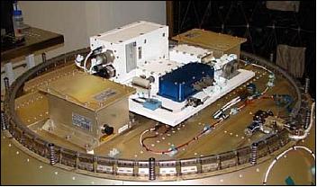
2) Build and flight-qualify a modular, reconfigurable spacecraft prototype structure, capable of hosting the avionics and system components of a full-sized microsatellite. To this effect the system was designed to be as self-contained as possible, even as it resides within a sounding rocket skin. As an instrument of opportunity, the structure also incorporates an electro-hydro-dynamic tunable thermal plate technology (multi-functional “plate”) for heat transfer and thermal test.
3) Obtain flight test performance data of all SMART subsystems, including the SpaceCube avionics and its interfaces, and the thermal plate technology. Flight environment data (axial/radial loads, thermal, vibration, and pressure), and optical data (of deceleration system) are also collected as a way of validating entry probe sensors and actuators and their operation.
SMART System
As a low-cost microsatellite prototype, SMART has a mix of heritage and ruggedized COTS (Commercial-off-the-Shelf) components chosen judiciously and tested extensively. For mission durations lasting up to a year (more is possible), the current system can prove adequate, given its limitations and constraints.
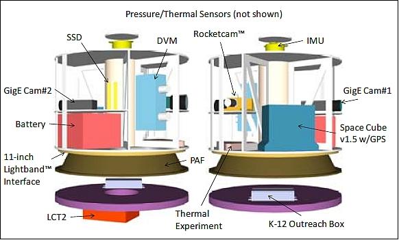
There are five main components in SMART: The SpaceCube avionics, the reconfigurable structure, instrument sensors, telemetry system, and the thermal system. A system block diagram is shown in Figure 1. Sensors (including the optical cameras) are used to monitor deployment, temperature, pressure, and acceleration environments, as well as position and inertial attitude. Sensor integration into the avionics provides for an account of the flight. Interface testing and sensor data is essential in assessing the avionics and overall system performance.

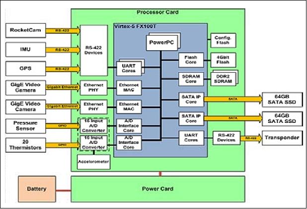
The heart of SMART is the SpaceCube v1.5, which provides computing capability to process the large amounts of sensor data, and distributes power to all components except the RocketCamTM and its associated DVM (Digital Video Module). The DVM handles RocketCam data, and pipes it through the SpaceCube for downlink and storage. The GigE (Gigabit Ethernet) camera video is processed within the SpaceCube, as are all other sensor data (IMU, GPS, pressure, and temperature). The full data set, at a rate of about 3 Gbit/s, is stored on-board by two SATA II SSDs (Solid State Drives), and a subset of this data downlinked via the LCT2 S-band at a rate of 10 Mbit/s. Because of the large amounts of data generated, real-time display of images will be at a much slower frame rate than the 15 to 90 fps (frames per second) actually stored on-board.
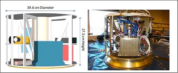
The SMART volume was constrained by the Terrier Improved Orion sounding rocket, with a bulbous 43.82 cm diameter skin (“fairing”). The PAF attaches to a 28 cm motorized LightbandTM bolt pattern of Planetary Systems, and to a ring in the rocket skin. No other attachment to the rocket is used, as to simulate an orbital launch vehicle configuration.
SpaceCube 1.5
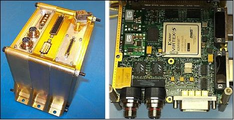
SpaceCube is a family of high-performance FPGA based on-board science data processing systems developed at the NASA/GSFC (SpaceCube 1.0, SpaceCube 1.5, SpaceCube 2.0). The goal of the project is to provide 10x to 100x improvements in on-board computing power while lowering relative power consumption and cost. The SpaceCube design strategy incorporates commercial rad-tolerant FPGA technology and couples it with an upset mitigation software architecture to provide “order of magnitude” improvements in computing power over traditional rad-hardened flight systems. 3)
SpaceCube 1.5, an intermediate version, has been designed to support a quick-turnaround sounding rocket flight and serves as a stepping stone to the next generation SpaceCube 2.0 system currently being developed under funding from ESTO (Earth Science Technology Office). SpaceCube 1.5 moves from the Virtex 4 to the Virtex 5 family of FPGAs and adds several industry standard plug-and-play interfaces such as Gigabit Ethernet and SATA-II (Serial Advanced Technology Attachment-II) interfaces.
The SpaceCube 1.5 avionics represent an evolutionary step from the flight qualified SpaceCube 1.0 system successfully flown during HST’s Servicing Mission 4 in May 2009 and on MISSE-7 (Materials on the International Space Station Experiment-7) payload and was installed on the Space Station in November 2009 (on STS-129, Nov. 16-27, 2009), providing inherent redundancy through multiple processor cores, high computational capability, and low power consumption.
The SpaceCube 1.5 system allows for legacy RS422 as well as Plug-and-Play-capable interfaces. These include GigE and SATA-II, using the 3 Gbit/s standard. The SpaceCube 1.5 itself is a small form-factor package, yet it services one of the highest performance payloads ever built at NASA/GSFC, with respect to data processing rates. The block diagram and interfaces of SpaceCube 1.5 is shown in Figure 5.
SMART Platform Structure
The structure design follows the architectural premises established during MR2 (Modular, Reconfigurable, Rapid) and MARS (Modular, Adaptive, Reconfigurable Systems) work, beginning in late 2002. From a structure perspective, the objective is to allow for layout changes using some basic components. In this case, “spider” N-truss components with a central thrust tube are arranged within a “spindle” geometry made to fit components that connect either through harness routing along the decks, or though routing within the tube. Mid-decks and top/bottom closing decks, plus vertical longerons complete the design. Simplicity and robustness are the end result. The current layout calls for a circular structure, which provides the most efficient interface to the sounding rocket.
An illustration of the platform structure is shown in Figure 6, together with reconfiguration options. The internal plates can slide up or down, depending on subsystem volume requirements. The truss structures can also be angled in different ways to accommodate larger boxes if needed, with a corresponding change in internal plate sizes. This design is simple, yet allows for flexibility in adjustments to accommodate subsystems of varying sizes. In addition, complete modules may be stacked-up depending on mission needs, and as allowable. The structural layout is modular and reconfigurable. Two configurations (requiring deck position adjustment) were flight qualified to the rather demanding launch environments found in typical sounding rocket vehicles. In fact, during layout the structure had to be modified to remove a deck and relocate a truss in order to allow more space for the space cube. This was done with minimal impact to the design (as these changes are built-in), and to the project.

AFSS (Autonomous Flight Safety System)
Flight termination of space launch vehicles is done today in the same manner it was done fifty years ago. The vehicle is tracked by precision radar, data is returned to a control room monitored by a Range Safety Officer, and, if necessary, flight termination commands are issued by high-powered transmitters to an onboard receiver. As the vehicle flies down range, additional coverage is required by multiple redundant radars and command transmitters linked together by highly reliable data networks.
Although many components of the flight termination system have been updated by modern technology, the cumbersome infrastructure, often deployed in remote locations or mobile platforms, is the same as it was in the 1960’s at inordinate cost to ranges — costs that are passed on to the Missions. Additionally, conventional termination systems are susceptible to weaknesses such as RFI (Radio Frequency Interference) or intentional jamming, and lag time associated with human response. A major concern of range safety is that the uplink is a frequency shared with radars. These radars are important DoD and Homeland Security assets. While coordination is possible during an actual launch, it is not offered during pre-launch tests and coordination failures have led to inability to transmit signals to rockets during flight.
The AFSS is being developed as a software system by the Wallops Flight Facility of NASA/GSFC and KSC (Kennedy Space Center) as a means of replacing all this with a simpler, safer onboard system that is orders of magnitude less expensive. The AFSS project will use GPS (Global Positioning Systems), modern IMUs (Inertial Measurement Units), and flight processors to monitor the progress of the launch vehicle with respect to multiple flight termination criteria and, if necessary, terminate the flight without relying on ground-based assets.
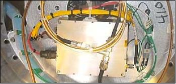
To validate the algorithms and software and to define the concept of operations for eventual use, AFSS has completed three successful developmental flights largely adapting commercial grade hardware to support testing. Figure 7 shows one such test system flown on “shadow-mode” (i.e., offline) on-board a SpaceX Falcon 1 launch vehicle, in March 2007. Further advancement of the technology, however, will require development of a lighter, compact and more robust platform on which to host the software for testing, demonstrations and eventually as a qualified flight termination system. The SMART platform is a promising candidate and with funding from ORS, the NASA AFSS software is being deployed on the SMART flight processors.
LCT2 (Low-Cost TDRSS/Telemetry Transmitter) and Space-based Range
The LCT2 was developed at the NASA/WFF (Wallops Flight Facility) to provide a low cost space based range solution for telemetering data. The LCT2 follows the roadmap towards a space-based range with the goal of reducing the operational cost of the range while increasing the response time to the launch industry, the ability to collect data and to ensure range safety.
Originally developed for use with the NASA TDRSS, LCT2 is a fully programmable software based transceiver containing modulator, transmitter, and receiver subsystems and has been used in a range of TDRSS and non-TDRSS applications to achieve not only satellite communications but direct to ground applications for high bit rate and as a ruggedized test bed for innovative modulation techniques. The modulator is capable of applying various types of modulation schemes to most data rates and formats. The transmitter subsystem RF output frequencies can be scaled to various frequencies and RF power output defined at build time across wide power output levels. The receiver subsystem can be programmed to receive various modulation schemes and bit rates based on customer or mission requirements. Modulation schemes, bit rate settings, RF frequency settings, and power level settings are based on customer and mission requirements and defined at project initiation. Figure 7 shows the LCT2 on-board SMART.
SMART On-board Sensors
SMART has three video cameras on-board: an Ecliptic Enterprises RocketCam™ Video Camera is used to ensure flight heritage and reliability, including the exercise of a legacy RS422 interface. Two industrial-grade GigE, progressive scan CCD color cameras are also used to test and validate fast interfaces to the SpaceCube avionics.
SMART SpaceCube 1.5 avionics application to small rocket systems will benefit from on-board acceleration data. Given volume and power constraints, an IC MEMS accelerometer was chosen. The MEMS IC chip was integrated into the avionics processor board, and provides two axes inertial acceleration data, along the board’s plane.
The pressure sensor is used to correlate altitude measurements during ascent and descent, and may be used as an event trigger in later flights. Although board IC sensors are available that would satisfy the current needs of SMART, their use is rather specialized. For this reason and to provide greater flexibility in its location, the use of a discrete, rugged pressure transducer was favored over an IC-type sensor.
Position measurements are essential in establishing not only launch vehicle performance, but also for normal operations once on-orbit. A commercial GPS receiver board was integrated into the SpaceCube 1.5 avionics chassis, and interfaces through one of SpaceCube’s RS422 I/O lines. Inertial attitude, acceleration, and magnetic field measurements are provided though an integrated IMU unit. The proper operation of AFSS software requires redundant position and/or inertial sensors. With a GPS and an IMU this requirement is met. Hence the existing configuration exercises the interfaces and basic architecture, and serves as hardware validation.
Given the R&D (Research and Development) nature of SMART, COTS components were used extensively. Nonetheless, all COTS parts were examined carefully, ruggedized, and extensively tested to reasonably assure mission success.
Launch
NASA launched successfully its first SMART payload on a Terrier Sounding Rocket from the Wallops Flight Facility on June 10, 2011 - a demonstration flight of NASA's SubTEC (Suborbital Technology Carrier) program. 4)
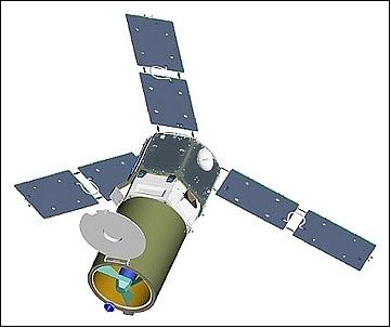
The US DoD (Department of Defense) launched its first SpaceCube 1.5 system onboard the ORS-1 (Operationally Responsive Space-1) minisatellite of USAF and managed by AFRL (Air Force Research Laboratory, Kirtland AFB, NM) on June 30, 2011 from MARS (Mid-Atlantic Regional Spaceport), Wallops Island, VA (Minotaur-1 launch vehicle). 5)
The ORS-1 satellite, built by ATK Space Systems of Beltsville, MD, grew out of the success of TacSat-3. ATK used the TacSat-3 bus to build the ORS-1 satellite with the addition of a propulsion module. The multispectral imager payload, SYERS-2 (Senior Year Electro-optical Reconnaissance System-2), was provided by Goodrich ISR Systems of Danbury, CON, the prime contractor of the project. The minisatellite had a mass of ~ 450 kg and was launched into an orbit of 400 km altitude with an inclination of 40º.
References
1) Jaime Esper, Thomas P. Flatley, James B. Bull, “Small Rocket/Spacecraft Technology (SMART) Platform,” proceedings of the 25th Annual AIAA/USU Conference on Small Satellites, Logan, UT, USA, Aug. 8-11, 2011, paper: SSC11-VII-6
2) “NASA Demonstrating SMART Technology Through Rocket Mission,” NASA, May 26, 2011, URL: http://www.nasa.gov/centers/wallops/news/SMARTfeature.html
3) Tom Flatley, “Advanced Hybrid On-Board Science Data Processor - SpaceCube2.0,” ESTF 2011 (Earth Science Technology Forum 2011), Pasadena, CA, USA, June 21-23, 2011, URL: http://esto.nasa.gov/conferences/estf2011/presentations/Flatley_ESTF20111.pdf
4) http://www.nasa.gov/centers/wallops/news/release-11-12.html
5) Turner Brinton, “Pentagon’s ORS-1 Imaging Satellite Carried to Orbit,” Space News, June 30, 2011, p. 7, URL: http://www.spacenews.com/launch/110630-ors1-sat-orbit.html
The information compiled and edited in this article was provided by Herbert J. Kramer from his documentation of: ”Observation of the Earth and Its Environment: Survey of Missions and Sensors” (Springer Verlag) as well as many other sources after the publication of the 4th edition in 2002. - Comments and corrections to this article are always welcome for further updates (eoportal@symbios.space).