Aditya-L1 (Name of the Sun in Sanskrit - Lagrange Point 1)
Non-EO
Atmosphere
Space environment
Operational (nominal)
Aditya-L1 is India's first dedicated solar observatory, launched by the Indian Space Research Organisation (ISRO) in September 2023. The mission aims to provide continuous, unobstructed observations of the Sun. Equipped with seven payloads, Aditya-L1 studies the Sun's photosphere, chromosphere, and corona, as well as solar wind and space weather phenomena. The mission seeks to enhance understanding of solar dynamics and their impact on Earth's environment.
Quick facts
Overview
| Mission type | Non-EO |
| Agency | ISRO |
| Mission status | Operational (nominal) |
| Launch date | 2 Sep 2023 |
| Measurement domain | Atmosphere |
| Measurement category | Atmospheric Winds |
| Measurement detailed | Atmospheric stability index, Solar Spectral Irradiance |
| Instruments | Magnetometer |
| Instrument type | Space environment, Atmospheric chemistry, Data collection, Hyperspectral imagers |
Aditya-L1 (Name of the Sun in Sanskrit - Lagrange Point 1) - Solar Coronagraph Mission
Overview
Aditya-L1 is a solar coronagraph mission of ISRO (Indian Space Research Organization) approved by the Space Commission of the Government of India. The project is a national effort involving the collaboration of the following institutions: ISRO, IIA (Indian Institute of Astrophysics), Udaipur Solar Observatory, ARIES (Aryabhatta Research Institute of Observational Sciences), TIFR (Tata Institute of Fundamental Research), and some Indian universities. In Sanskrit, Aditya is the name of the sun. 1) 2)
The overall objective is to study the solar dynamics in the chromosphere and corona with a suite of instruments including a coronagraph and a UV imager. The orbit around L1 provides continuous solar observations without any eclipse/occultation and is an excellent outpost outside Earth's magnetic field to make in-situ measurements of incoming charged particles.
Background
Initially, the Aditya-1 mission was conceived as a 400 kg class minisatellite carrying one payload, the VELC (Visible Emission Line Coronagraph) and was planned to launch in a 800 km LEO (Low Earth Orbit). However, a satellite placed in the halo orbit around the Lagrangian point 1 (L1) of the Sun-Earth system has the major advantage of continuously viewing the Sun without any occultation/ eclipses. Therefore, the Aditya-1 mission has now been revised to "Aditya-L1 mission" and will be inserted in a halo orbit around the L1, which is 1.5 million km from the Earth. The satellite carries additional six payloads with enhanced science scope and objectives. 3)
The revised and enhanced Aditya-L1 mission was approved by the Indian Government in 2015 and the satellite will be launched in the timeframe 2019 – 2020 by a PSLV-XL vehicle from Sriharikota. This will be the first Indian space mission to study the Sun, and also the first Indian mission to be placed at Lagrangian point L1 from where continuous solar observations are possible
Aditya-1 was meant to observe only the solar corona. The outer layers of the Sun, extending to thousands of km above the disc (photosphere) is termed as the corona. It has a temperature of more than a million degree Kelvin which is much higher than the solar disc temperature of around 6000 K. How the corona gets heated to such high temperatures is still an unanswered question in solar physics.
Aditya-L1 with additional experiments can now provide observations of Sun's Photosphere (soft and hard X-ray), Chromosphere (UV) and corona (Visible and NIR). In addition, particle payloads will study the particle flux emanating from the Sun and reaching the L1 orbit, and the magnetometer payload will measure the variation in magnetic field strength at the halo orbit around L1. These payloads have to be placed outside the interference from the Earth's magnetic field and could not have been useful in LEO.
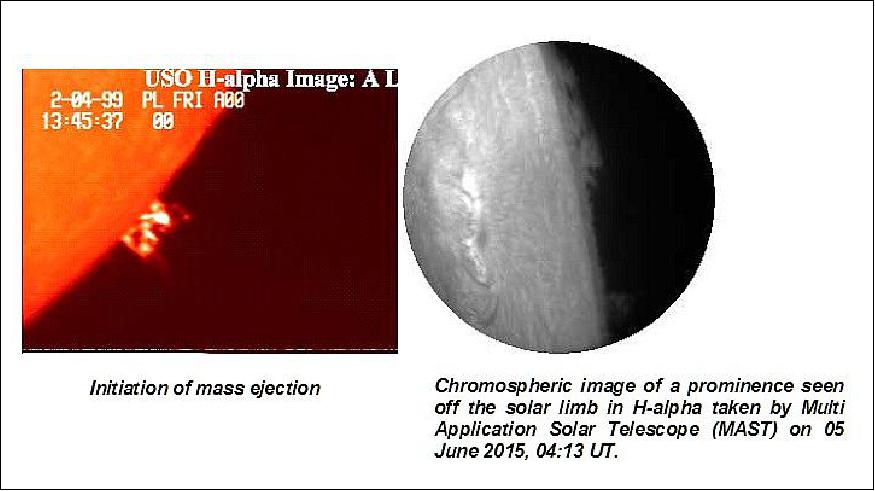
Legend to Figure 1: USO is located in Udaipur, Rajasthan in India on an island in the Fateh Sagar Lake. The observatory was built in 1976. USO is known for its solar observations, which include high-resolution solar chromospheric, magnetic field, velocity, and spectral observations, for studies pertaining to solar flares, mass ejections, and the evolution of solar active regions. Since 1981, USO has been managed by the PRL (Physical Research Laboratory), Ahmedabad, for the Department of Space, Government of India.
Spacecraft
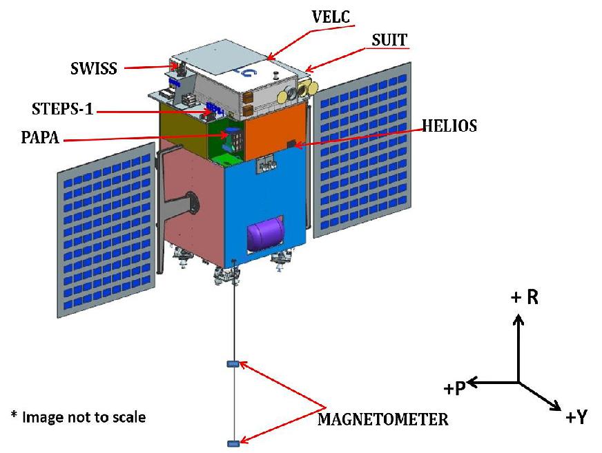
The Aditya spacecraft is 3-axis stabilized using the IMS (Indian MiniSatellite) bus of SARAL (Satellite with Argos and AltiKa) mission heritage (launch in 2011). The spacecraft is developed as a standard satellite bus by ISAC (ISRO Satellite Center), which can be used for missions for remote sensing, communications and space science applications.
The structure of Aditya-1 consists of aluminum skin honeycomb sandwich structure, a cuboid of size 89 cm x 89 cm x 61.5 cm. The payload will be accommodated on the top deck with localized corner brackets. The total mass of the spacecraft, including the payload, is expected to be around 400 kg.
AOCS (Attitude and Orbit Control System)
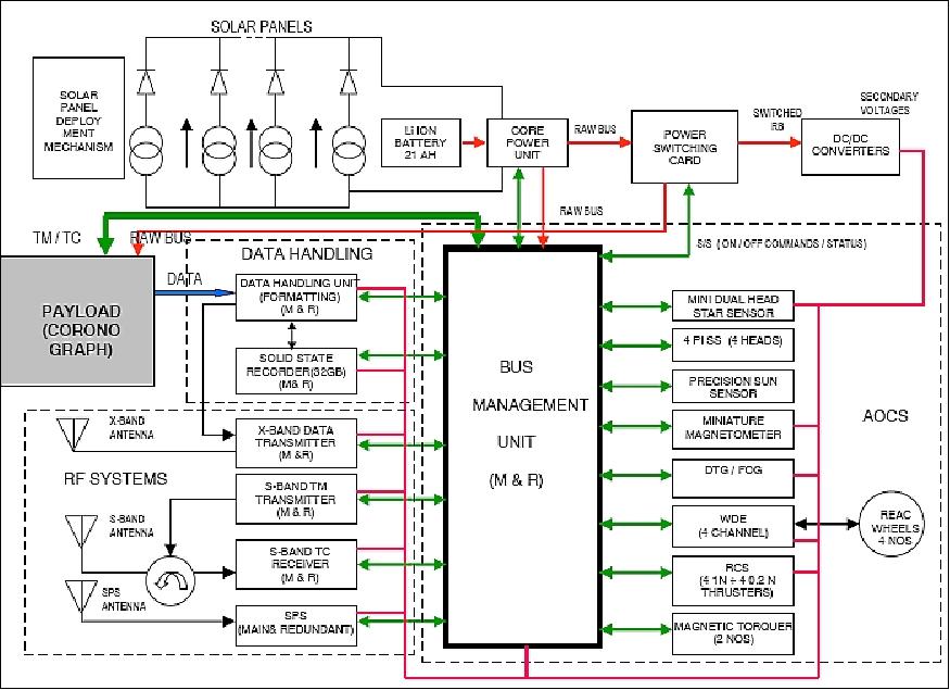
The AOCS configuration consists of various types of sensors for measurement of attitude errors, control electronics and different types of actuators such as reaction wheels, magnetic torquers and reaction control thrusters to impart thrust/torque to the spacecraft in the desired direction. The sensor system consists of a star sensor, sun sensors (4π FOV), magnetometer and precision sun sensor and the IRU (Inertial Referencing Unit). The IRU consists of three miniature gyroscopes, dynamically tuned and cluster mounted, and suspended with vibration isolators. Considering the stability requirement of < 5 x 10⁻⁵ º/s, the option of using a FOG (Fiber Optic Gyro) solution is being studied. Three types of actuators are being used, reaction wheels, magnetic torquers and RCS (Reaction Control Subsystem) thrusters to control the orbit and the attitude of the spacecraft.
EPS (Electric Power Subsystem)
The spacecraft features one solar wing with 2 panels, each of size 120 cm x 81 cm. The solar panels are stowed on the VD02 side in the launch configuration; they are programmed to auto deploy immediately after injection into the orbit. An average power of 400 W is available using multi-junction solar cells. A Li-ion battery provides power during the eclipse phase of the orbit. The EPS is configured as a single regulated, battery tied bus with one battery. The power electronics package performs the functions of solar array string switching, battery charge/discharge control and power conditioning and distribution. The power distribution scheme is based on the specific voltage and current requirements for all subsystems.
The BMU (Bus Management Unit)
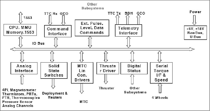
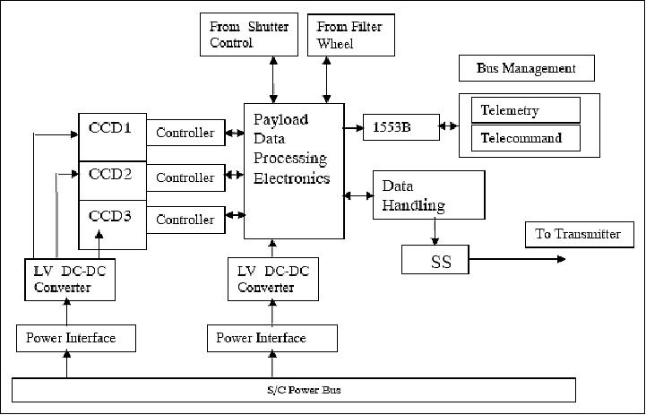
With the OBC takes care of all data handling functions using the MIL‐STD‐1553B standard interface with the star sensor and the payload. The payload data handling subsystem employs serial interfaces to the baseband data handling formatter. The formatter receives the payload data packets, annotates these with the housekeeping data, and deposits them onto the SSR. The BMU is built around state-of-the-art technologies using FPGAs and ASICs. It interfaces with TTC (RF), sensors, power, thrusters, MTCs (Magnetic Torque Controllers), gyros, wheel drive electronics and the payload.
The SPS (Satellite Positioning System)
Provides the state vector (position, velocity and time) of the spacecraft in real-time. A miniaturized GPS receiver is being used. The state vector of the satellite is sent to BMU through a serial interface. The system works in cold start mode, that is, it searches the sky, receives the GPS signals, and computes position, velocity and time without any prior information of the spacecraft' state vector.
RF Communications
The TT&C transponder consists of a S-band receiver, a transmitter and the antenna subsystem. The receiver is of a non-coherent type using the FM/PSK/PCM modulation scheme. The receiver provides frequency demodulation of the onboard received signal to extract the two switching PSK subcarrier signals. This output will be PSK demodulated to obtain data and clock. The FM/PSK demodulation is performed in the digital domain. The TT&C antenna offers a near omni-directional coverage to provide a reliable link during both the initial launch phase and on-orbit phase.
The DHS (Data Handling Subsystem)
Has two components: the BDH (Baseband Data Handling) subsystem and the RF transmitter. The payload data that is received by the BDH is formatted, randomized and fed to the transmitter. The transmitter accepts the digital data stream from the BDH, modulates the data in QPSX (Quadrature Phase Shift Keying) mode and transmits the data to a ground station using a conventional X-band (8.125 GHz) antenna. The DHS provides the following operational capabilities:
- Input data rates: ~42 / 4.8 /2.4/ 56/0.224 Mbit/s
- Data interface: Serial bit stream
- Channel coding: RS (Reed Solomon) coding (255, 233), I = 5
- Transmission data rate: 32 Mbit/s
- Modulation: QPSK
- SSR (Solid State Recorder) Capacity
32 Gbit on on-board storage. The SSR has the provision to support simultaneously data recording and playback. This feature is required to get uninterrupted observational data from the payload.
The X-band data transmission uses an 8 W SSPA (Solid State Power Amplifier). The data transmission is through a shaped beam antenna.
Launch
The Aditya-L1 minisatellite was launched on a PSLV-XL vehicle from the SDSC (Satish Dhawan Space Center, SHAR) of ISRO on the south-east coast of India, on September 2, 2023 at 06:20 UTC. 7)
Orbit
The Aditya-L1 spacecraft has been inserted in a halo orbit around the Sun-Earth Lagrangian Point L1, which is 1.5 million km from Earth. The coast phase to L1 is approximately 100 days.
Mission Status
• July 2, 2024: ISRO's Aditya-L1 spacecraft completed its first full halo orbit around the Sun-Earth Lagrange Point 1 (L1), following its insertion into this orbit on January 6, 2024, after launching on September 2, 2023. The 178-day orbit requires periodic corrections due to gravitational perturbations, with three station-keeping maneuvers successfully executed so far—the latest on July 2—to maintain the intended path. This milestone validated the precision of ISRO’s in-house flight dynamics software, confirming its effectiveness in managing complex orbital dynamics around L1. 8)

• September 2, 2023: Aditya-L1 was launched at 06:20 UTC from the SDSC (Satish Dhawan Space Center, SHAR) launch pad at Sriharikota, India, on a PSLV-XL vehicle. 7)


Sensor Complement
With the inclusion of multiple payloads, this project also provides an opportunity to solar scientists from multiple institutions within the country to participate in spaceborne instrumentation and observations. Thus, the enhanced Aditya-L1 project will enable a comprehensive understanding of the dynamical processes of the sun and address some of the outstanding problems in solar physics (Ref. 3).
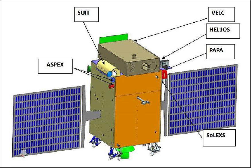
VELC (Visible Emission Line Coronagraph)
The main payload continues to be the solar coronagraph with improved capabilities. The main optics for this experiment remains the same. The instrument optical axis is required to be pointed towards the center of the sun continuously. The solar coronagraph is being designed and developed at IIA (Indian Institute of Astrophysics) in Bangalore (PI: Jagdev Snigh). Among other functions, ISRO is providing the detectors for the instrument.4) 5)
The objective of VELC is to study the diagnostic parameters of solar corona and dynamics and origin of CMEs (Coronal Mass Ejections) in 3 visible and 1 infrared channels; magnetic field measurement of solar corona down to tens of Gauss. 6)
VELC will Address the Following Science Aspects
• Role of wave in coronal heating
• How are CMEs accelerated ?
• What is the nature of the interaction between the CME plasma and the magnetic field that drives the eruption ?
• What is the configuration of the magnetic field in the corona?
• How are the different components of the solar wind, slow and fast, accelerated ?
• To what degree do coronal inhomogeneities affect the heating and acceleration process ?
Observational Requirements
• Imaging of the inner corona (1.05-3.0 solar radii) at high spatial and at high cadence (1-60 s)
• Spectroscopic measurements (FOV: 1.05-1.5 solar radii) in two visible and one infrared line for understanding the heating, dynamics, temperature, density and structure of the solar corona.
• Spectro-polarimetry in near infrared for topology and magnetic field measurements.
The data will be complemented with ground-based telescope data to provide the complete atmospheric coupling of the solar magnetic fields from the photosphere to the corona.
VELC Instrument Design
Considering the scientific goals and the required SNR levels, a 20 cm off-axis internally occulted coronagraph and the associated back-end instruments are selected. An off-axis design is chosen to reduce the scattered light resulting from the spiders that hold the secondary mirror. This is an important aspect that is considered for the accurate coronal intensity and polarization measurements. The selection of internal occultation is driven by the science requirement to study inner corona. 7)
The 20 cm coronagraph uses an off-axis parabolic mirror which simultaneously images the visible emission lines at 5303 Å [Fe xiv] and 6374 Å [Fe x] using narrowband imaging in the emission lines, and imagery in the 5800Å range using the continuum/broadband imaging technique for CME studies. The FOV in the solar corona is from 1.05 to 3.0 Rsun for broadband imaging and 1.05 to 1.5 Rsun for narrowband imaging. A dichroic beam splitter, polarization optics, and narrowband filters are accommodated in the optical path.
The CCD detector array has a format of 2 k x 2 k with a pixel size of < 12 µm. The fast cadence of the imaging instrument will allow to study the high frequency waves and its association with the coronal heating. Linear polarization measurements will also be made to map the magnetic topology of the solar corona. The large FOV capability of this instrument allows the study of CMEs. The primary optics has a micro-roughness of better than 0.2 nm.
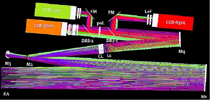
Legend to Figure 9: EA (Entrance Aperture), M1 (Primary Mirror), M2 (Secondary Mirror), M3 (Mirror to reject the solar disk light), CL (Collimating Lens), LS (Lyot Stop), M4 (Imaging mirror), Pol. (Polarization Filter Wheel), DBS (Dichroic Beam Splitter), CCD (Charge-Coupled Device), and FM (steering mirror).
The instrument operates in four observing modes.
Mode | FOV | Binning | Mpixel/frame | Frame rate (1/s) | Data quantization (bit) | Observation time (s) | Data volume (Gbit) |
Intensity oscillation | 1.05-1.5 Rsun | Yes | 1 | 3 | 14 | 300 | 12.6 |
Loop dynamics | 1.05-1.5 Rsun | No | 4 | 0.1 or 0.05 | 12 | 1800 or 3600 | 8.64 |
Magnetic topology | 1.05-1.5 Rsun | No | 4 | 0.005 | 14 | One per day | 0.056 |
CME studies | 1.05-3.0 Rsun | Yes (2 x 2) | 1 | 0.016 | 14 | 13 hours/day | 10.92 |
Total volume |
|
|
|
|
|
| 32.22 x 2 = |
SUIT (Solar Ultraviolet Imaging Telescope)
The SUIT instrument is being developed at IUCAA (Inter-University Center for Astronomy & Astrophysics), located on the Pune University Campus in Pune, India. The objective is to image the spatially resolved Solar Photosphere and Chromosphere in near Ultraviolet (200-400 nm) and measure solar irradiance variations.
SUIT will Tackle the Following Issues
• Coupling and dynamics of the solar atmosphere: What are the processes through which the energy is channelized and transferred from the photosphere to the chromosphere and then to the corona?
• Initiation of CMEs:What are the kinematics of erupting prominences during the early phase?
• Solar irradiance studies:Temporal variation and the spectral variation of the source regions.
• Prominence studies: What are the mechanisms responsible for stability, dynamics and eruption of solar prominences?
Observational Requirements
• Full disk observations in NUV(200–400 nm) in about 10 passbands using a filter-wheel mechanism.
• Combined medium and narrow-band filter imager with low stray light and high contrast to measure and monitor brightness contrast of solar magnetic features.
• Total FOV ~ 1.1 solar radii to overlap the FOV of VELC.
• Observations with different settings of cadence, exposure time, angular resolution, regions of interest, etc.
The data will be complemented with ground-based telescope data to provide magnetic field measurements. SUIT will provide continuous observations from photosphere, chromosphere and lower transition region.
ASPEX (Aditya Solar wind Particle Experiment)
The ASPEX instrument is being developed at PRL (Physical Research Laboratory), Ahmedabad, India. The objective is to study the variation of solar wind properties as well as its distribution and spectral characteristics.
ASPEX is Aimed to
• Determine the variation of the spectrum of solar wind ions, supra-thermal ions and solar energetic particles during the solar cycle.
• Determine the variation of the thermal anisotropy of the constituents of the solar wind (protons, α-particles, and heavy ions) which is a measure of the efficacy of various acceleration and heating processes thought to occur in the interplanetary medium.
• Study of the supra-thermal tail of solar wind particles and temporal variation.
• Investigate the energy dependence of proton/alpha ratio and the temperature anisotropy of solar wind particles.
Instrument Components
• SWIS (Solar Wind Ion Spectrometer) to measure both the angular and energy distributions concurrently in addition to being able to separate protons, α-particles and heavy ions in the 100 eV to 20 keV range.
• STEPS (Supra Thermal Energetic Particle Spectrometer). STEPS will sample the solar wind along four different directions and study the supra-thermal particles observed in the solar wind in the 20 eV to 5 MeV range.
ASPEX will complement coronagraphic observations by determining the arrival time of interplanetary CMEs at L1.
PAPA (Plasma Analyzer Package for Aditya)
The PAPA instrument is being developed at SPL (Space Physics Laboratory), located at VSSC (Vikram Sarabhai Space Center),Trivandrum, Kerela State, India. The goal is to understand the composition of solar wind and its energy distribution.
The Scientific Objectives are
• Continuous measurement of the solar wind and interplanetary electron distribution functions in the energy range 0.01-3 keV to extract the interplanetary magnetic field structure and topology.
• Study the composition of the solar wind and thereby understanding about the origin of the solar wind and particle acceleration mechanism.
Instrument Components
• SWEEP (Solar Wind Electron Energy Probe) to measure the solar wind and interplanetary electron distribution functions in the energy range 0.01-3 keV.
• SWICAR (Solar Wind Ion Composition Analyzer) to measure the kinetic temperatures and mean speeds of all major ion species in the mass range of 1-3 amu (atomic mass unit).
SoLEXS (Solar Low Energy X-ray Spectrometer)
The instrument is being developed at ISAC (ISRO Satellite Center), Bangalore, India. The objective is to monitor the X-ray flares (1-30 keV) for studying the heating mechanism of the solar corona.
The Payload will Provide
• Data for the study of the DC heating mechanism.
• The physical characteristics of solar flares ranging from the X-class to the A-class along with its association of CMEs.
• Independent measure of coronal temperature and DEM (Differential Emission Measure) as well as abundances of coronal plasma.
• Study of the CME-flare relation and its physical mechanism.
Observational Requirement
• Single pixel SDD (Silicon Drift Detector) to observe the complete solar disk in the 1-30 keV range.
• Large dynamic range and high spatial resolution (<250 eV @ 5.9 keV) to measure the large variation in flux.
• FOV = 1º.
SoLEXS along with VELC, SUIT and the hard X-ray instrument will provide data to study the kinematics of solar flares and their energy content.
HEL1OS (High Energy L1 Orbiting X-ray Spectrometer)
The HEL1OS instrument is being developed at ISAC and at PRL (Physical Research Laboratory) of USO (Udaipur Solar Observatory). The objectives are to observe the dynamic events in the solar corona and provide an estimate of the energy used to accelerate the particles during the eruptive events (a spectrometer that views the Sun as a star and is designed to study hard X-ray (HXR) emission from 10 keV to 150 keV during the impulsive phase of solar flares).
The Main Science Goals of HEL1OS are
• Study of explosive energy release, acceleration and transport of electrons using fast timing measurements and high resolution spectral studies.
• Study of the evolution of low-energy non-thermal electron cut-off using high spectral resolution measurements.
• Provide fast continuous timing data for the study of sub-second variability during flares.
• Understanding the science of eruptive events using complimentary multi-wavelength observations.
Observation Requirement
• Two types of semiconductor detectors. CdZnTe and CdTe in the overall energy range of 10-150 keV will cover the overlap between thermal and non-thermal components of a solar flare.
• Collimator FOV is 3º cone angle.
HEL1OS data will be complemented by VELC, SoLEXS, SUIT and ground observations in the radio bands.
Magnetometer
The instrument is being developed by LEOS (Laboratory for Electro Optics Systems) and ISAC, both institutions are located in Bangalore..
References
1) V. Koteswara Rao, "Aditya-1, Indian Minisatellite Space Coronagraph," Proceedings of the 61st IAC (International Astronautical Congress), Prague, Czech Republic, Sept. 27-Oct. 1, 2010, IAC-10.B4.2.2
2) Divya Gandhi, "ISRO planning to launch satellite to study the sun," The Hindu, January 13, 2008, URL: https://web.archive.org/web/20100724074507/http://www.hinduonnet.com:80/2008/01/13/stories/2008011354801000.htm
3) "Aditya-L1 First Indian mission to study the Sun," ISRO, Feb. 2, 2016, URL: http://www.isro.gov.in/aditya-l1-first-indian-mission-to-study-sun
4) "Indian Institute of Astrophysics," brochure, URL: http://www.iiap.res.in/files/brochure_final.pdf
5) B. Raghavendra Prasad for the Team Aditya (IIA, ISAC, LEOS, USO, SAC, VSSC), "Aditya I - An Overview," 2011, URL: http://www.iiap.res.in/meet/sol2011/sol_ppt/RPrasad.pdf
6) S. Seetha, "Proposed Aditya-L1 Mission," Conference on Coupling and Dynamics of the Solar Atmosphere", Pune, India, Nov. 10-14, 2014, URL: http://www.iucaa.ernet.in:8080/jspui/bitstream/11007/2780/1/Aditya-talk-11Nov14.pdf
7) Jagdev Singh, B. Raghavendra Prasad, P. Venkatakrishnan, K. Sankarasubramanian, Dipankar Banerjee, Raja Bayanna, Shibu Mathew, Jayant Murthy, Prasad Subramaniam, R. Ramesh, S. Kathiravan, S. Nagabhushana, P. K. Mahesh, P. K. Manoharan, Wahab Uddin, S. Sriram, Amit Kumar, N. Srivastava, Koteswara Rao, C. L. Nagendra, P. Chakraborthy, K. V. Sriram, R. Venkateswaran, T. Krishnamurthy, P. Sreekumar, K. S. Sarma, Raghava Murthy, K. H. Navalgund, D. R. M. Samudraiah, P. Narayan Babu, Asit Patra, "Proposed visible emission line space solar coronagraph," Current Science, Vol. 100, no 2, Jan. 25, 2011, URL: http://aditya.iiap.res.in/sites/aditya.iiap.res.in/files/Artcile_currentsc.pdf
7) Pandey Geeta, “Aditya-L1: India successfully launches its first mission of the Sun”, BBC News, September 2, 2023, URL: https://www.bbc.com/news/world-asia-india-66643805
8) ISRO, “Aditya-L1 Mission: Completion of First Halo Orbit”, July 2, 2024, URL: https://www.isro.gov.in/Aditya_L1_Mission_Completion_of_First_Halo_Orbit.html