AeroCube 7-OCSD-A (AeroCube 7 - Optical Communication and Sensor Demonstration-A)
Non-EO
Operational (extended)
Technology and Research
Quick facts
Overview
| Mission type | Non-EO |
| Mission status | Operational (extended) |
| Launch date | 08 Oct 2015 |
AeroCube 7-OCSD-A (AeroCube 7 - Optical Communication and Sensor Demonstration-A)
Spacecraft Launch Mission Status Sensor Complement Optical Ground Station References
In 2012, The Aerospace Corporation (El Segundo, CA) was selected by the NASA Small Spacecraft Technology Program (SSTP) to conduct a subsystem flight validation mission to test COTS (Commercial-of-the-Shelf) components and subsystems that will enable new communications and proximity operations capabilities for CubeSats and other spacecraft. Aerospace proposed optical communications using milliradian (mrad) beam spreads that are compatible with near-term CubeSat pointing capabilities. The baseline mission will use a ~10 W modulated fiber laser with a 1.4º angular beam-width on a 1.5U CubeSat (AeroCube-OCSD) and a 30 cm diameter telescope located on Mt. Wilson in southern California to receive optical pulses. The project plans on demonstrating the baseline 5Mbit/s optical link with a stretch goal of 50 Mbit/s. 1)
Aerospace also proposed integrating an automotive anti-collision radar system and an enhanced optical mouse sensor into these CubeSats to enable future proximity operations. After launch,the two 1.5U AeroCube-OCSD CubeSats will be ejected from the same P-POD and brought within 200 m of each other using on-board GPS for position and velocity determination, variable drag for cooperative orbit rephasing, and cold gas thrusters for proximity maneuvering. Each CubeSat has deployed wings that allow varying the ballistic coefficient by at least a factor of 4 by changing the spacecraft orientation with respect to the flight direction.
The OCSD flight demonstration has the following mission requirements:
• Demonstrate optical communications from a CubeSat to a 30 cm diameter ground station terminal from LEO at a transmission rate of at least 5 Mbit/s.
• Demonstrate tracking of a nearby spacecraft using a COTS automotive anti-collision radar sensor and an inexpensive optical mouse sensor.
Background
Advances in micro- and nanoelectronics have enabled unprecedented data collection and storage capabilities in spacecraft of all sizes. A current generation 15 Mpixel color imager operating at 30 Hz can generate over 10 Gbit/s of raw data. Even with low-loss video compression, data rates can easily exceed 200 Mbit/s. Recording this compressed video over an entire orbit would require about 132 GB; slightly more than the 128 GB storage capacity of a micro SD flash memory card. A TByte of data can be readily stored in a CubeSat, and with a little more effort, over 10 TB is possible. 2)
Sending this amount of data from a power and antenna-gain limited small satellite to the ground is a challenge. A good S-band CubeSat downlink can handle a data rate of several Mbit/s. Downloading a TByte using a single ground station at a rate of 5 Mbit/s with an average of four 10 minute passes per day (very optimistic) would take almost 2 years. Storing TBytes of information is easy; sending it to the ground is hard. Either an order-of-magnitude or more increase in the number of ground stations, or an equivalent increase in downlink data rates, is required to enable more reasonable data download times.
Laser communications offer Gbit/s data rates; a several order-of-magnitude increase in rate compared to RF (Radio Frequency) communications. NASA's LLCD (Lunar Laser Communication Demonstration), an experiment on the LADEE (Lunar Atmosphere and Dust Environment Explorer), sent data from lunar orbit to the Earth in late 2013 at a record-breaking rate of 622 Mbit/s. This was six times faster than previous RF communications from the moon, using a transmitter with half the weight and one quarter the input power of an equivalent RF system. Note that communications from the moon, with a link length of about 400,000 km, is many orders-of-magnitude harder than from LEO (Low Earth Orbit), with a link length of about 1000 km.
Members of The Aerospace Corporation, in collaboration with Tesat-Spacecom, previously demonstrated 5.625 Gbit/s bidirectional laser communications between a 6.5 cm diameter ground station at the ESA (European Space Agency) Optical Ground Station in Izana, Tenerife Island, and a 12.5 cm diameter terminal mounted on the NFIRE (Near Field Infrared Experiment) satellite in LEO (Low Earth Orbit). The spacecraft terminal had a mass of 35 kg, a power consumption of 120 W, a 0.5 m x 0.5m x 0.6 m size, and transmitted 0.7 W at 1064 nm wavelength. This high-performance system with a ~50 µrad angular beam width and gimballed pointing system would obviously not fit in a CubeSat (Ref. 1).
Eliminating the optical gimbal and increasing the angular beam width to several mrad to enable spacecraft body-pointing of the laser would enable a smaller, lighter optical terminal. This approach takes advantage of the exceptionally low moments-of-inertia of CubeSats, and their ability to perform rapid slew maneuvers. The Aerospace CubeSats can typically rotate about a single axis at rates of 10-20º/s.
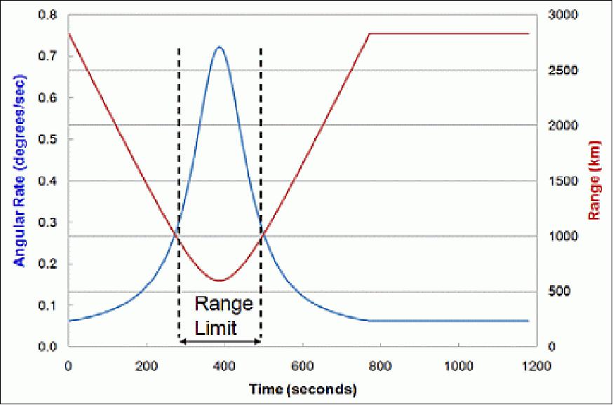
Figure 1 shows the angular rate and range for a spacecraft in a 600 km altitude orbit with a vertical pass over an optical ground station. Required rotation rates are less than 0.8º/s, and overhead passes at lower maximum elevation will have even lower rotation rate requirements. For OCSD, the project selected a maximum link length of 900 km. At 600 km altitude, this yields a minimum elevation angle of 30º, and a maximum laser communications period of 180 s.
Optical communications from LEO: Optical communications exploits the significantly narrower angular antenna beam widths, for a given antenna diameter, for visible through infrared light compared to radio frequency (RF) waves or microwaves. Optical communications systems typically have mrad through µrad angular beam widths while RF/microwave angular widths are measured in tens to thousands of mrad. Table 1. shows frequencies, wavelength, energy, and minimum angular beam width for a 10 cm diameter antenna at representative UHF, microwave, millimeter, THz (sub-mm), VIS (Visible), and VNIR (Visible Near-Infrared) frequencies. At UHF, there is no directionality while at VNIR, the theoretical minimum beam spread is only 5.5 µrad. The latter beam spot size at 1000 km range would be only 5.5 m in diameter. Accurate pointing is essential for long-range optical communications.
The fourth column in Table 1 lists the energy of a representative photon in electron volts (eV). At RF wavelengths, these energies are so small, that the quantized nature of light is typically ignored. RF receivers detect incoming signals in the 0.1-100 x 10-15 W (femtowatt) range which corresponds to over 10 million photons per bit. Optimized optical receivers, on the other hand, can detect single photons. In practice, typical photoreceivers need between 10 and several hundred photons to identify a bit of information.
Band | Frequency | Wavelength | Energy | Beam width |
UHF | 435 MHz | 69 cm | 1.8 µeV | 3.6 rad |
S-band | 2.45 GHz | 12 cm | 10 µeV | 0.64 rad |
X-band | 10.2 GHz | 2.9 cm | 42 µeV | 0.15 rad |
W-band | 77 GHz | 3.9 mm | 0.3 meV | 20 mrad |
Sub-mm | 0.35 THz | 860 µm | 1.4 meV | 4.5 mrad |
VNIR | 283 THz | 1.06 µm | 1.17 eV | 5.5 µrad |
VIS (red) | 460 THz | 0.65 µm | 1.9 eV | 3.4 µrad |
Update in Second Phase of Development 3)
The original goals were to demonstrate a satellite-to-ground laser downlink with a data rate of greater than 5 Mbit/s, and to demonstrate proximity operations using two 1.5U AeroCube-OCSD spacecraft with on-board propulsion.
The project decided to significantly improve the 5 Mbit/s laser downlink data rate during the design and R&D phase by replacing the proposed 300 mW output direct drive laser diode with a two stage 10 W fiber laser. This change enabled a potential 33X improvement in data rate. An additional 7X improvement was made possible by utilizing a newly-available 80 cm diameter telescope for our ground station instead of the proposed 30 cm diameter telescope. These two improvements increased the potential downlink data rates by over two orders-of-magnitude to approach 1 Gbit/s. This may be a world's record in mission requirements creep, but we wanted to demonstrate data rates far in excess of any RF rates used in any previous or near-term CubeSat. This, of course, made the build, test, and integration phase much harder than originally planned.
Multiple system redesigns for the laser downlink and other systems caused a four month schedule delay, and the project still wanted additional time to further improve laser transmitter packaging for assembly, and overall reliability. Fortunately, the project was offered an additional launch opportunity, and decided to fly the qualification spacecraft as a pathfinder test. "Test as you fly" is one of the tools the project uses to decrease CubeSat mission risk. The project is now adding "Fly as you fly" to the tool kit.
The goals for the Pathfinder flight unit are:
1) Test the new attitude control system with dual star trackers and determine spacecraft pointing errors. We need at least 0.15º (3σ) pointing, but expect an order-of-magnitude better.
2) Test the laser downlink using both open- and closed-loop control with data rates up to 40 Mbit/s. Anything above 5 Mbit/s is a mission success.
The Pathfinder unit was delivered in April 2015 without a propulsion system since it was not necessary to meet the Pathfinder goals. On-orbit testing will focus first on attitude control performance, followed by laser downlink tests. The results from the attitude control tests will be used to fix any remaining hardware and software issues in the flight unit, and to set the divergence angle of the downlink laser. In addition, the Earth imaging camera and the side-looking camera were disabled; they had last-minute harnessing problems and were left unconnected since they were not required for this first flight.
The goals for the last two OCSD CubeSats are:
1) Test orbit control using variable drag
2) Test orbit control using the on-board water vapor thruster
3) Perform proximity operations
4) Determine range between the two spacecraft using GPS-derived ephemerides, and/or the laser range-finder, and
5) Test the laser downlink using both open- and closed-loop control with data rates up to 500 Mb/s. This can be accomplished using the 6 W laser downlink with MAFIOT at 700 km or shorter range. For the 2 W downlink, the FWHM (Full Width Half Maximum) angular beam spread has to be reduced to 0.13º, and the attitude control system has to provide 0.065º pointing accuracy. The results from the Pathfinder flight will tell if this is possible.
Meeting goals 1 through 4 with a demonstrated laser downlink data rate in excess of 5 Mbit/s would constitute complete OCSD mission success. Goal 5 is two orders-of-magnitude higher than the required 5 Mbit/s downlink data rate for mission success. This "super goal" was established internally to set the stage for future laser downlinks with data rates in excess of 1 Gbit/s.
Spacecraft
The OCSD flight hardware will consist of three 1.5‐unit (1.5U) CubeSats that will be launched as secondary payloads on two rideshare missions. A single pathfinder satellite will be launched in October 2015, followed by a pair of Block‐II satellites in 2016.The pathfinder satellite will demonstrate all the subsystems required for the primary OCSD mission, and will be used to evaluate the performance of the attitude‐control system. 4)
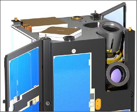
The AeroCube-OCSD pathfinder flight hardware consists of one 1.5U CubeSat that will be ejected on-orbit from a CubeSat deployer. Figure 2 shows a photograph of the Pathfinder that was delivered to the launch provider. It contains a 6 W output downlink laser, an uplink laser receiver, two independent 915 MHz communications transceivers, a GPS receiver, a 3-axis attitude control system designed for better than 0.15º pointing accuracy, a Jenoptik DLEMSR laser rangefinder,3 two star trackers, a color camera with 180º field of view, two deployable solar panels, and a distributed computing system composed of over 20 microprocessors and 3 FPGAs (Field-Programmable Gate Arrays). An 8 GB flash RAM memory card is used for data storage. The Earth-pointing face is the top face in Figure 2; this face contains the uplink laser receiver, the transmitter output window, a medium-gain patch antenna, a sun sensor, a laser retro-reflector, an ultra-wide angle camera, an LED beacon, and the legacy Earth nadir sensor of the Aerospace Corporation. The locations are shown in the schematic drawing in Figure 3.
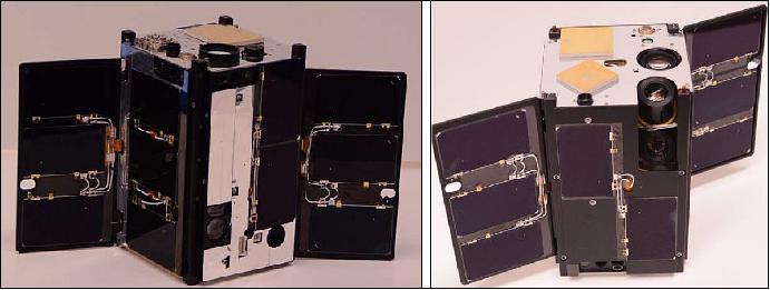
Legend to Figure 2: Figure 2 left shows the opposite sides of the Pathfinder spacecraft. The top surface now contains the GPS receive antenna, an omnidirectional patch antenna, a sun sensor, a laser retroreflector, an LED beacon, a narrow field of view camera, and a star tracker.
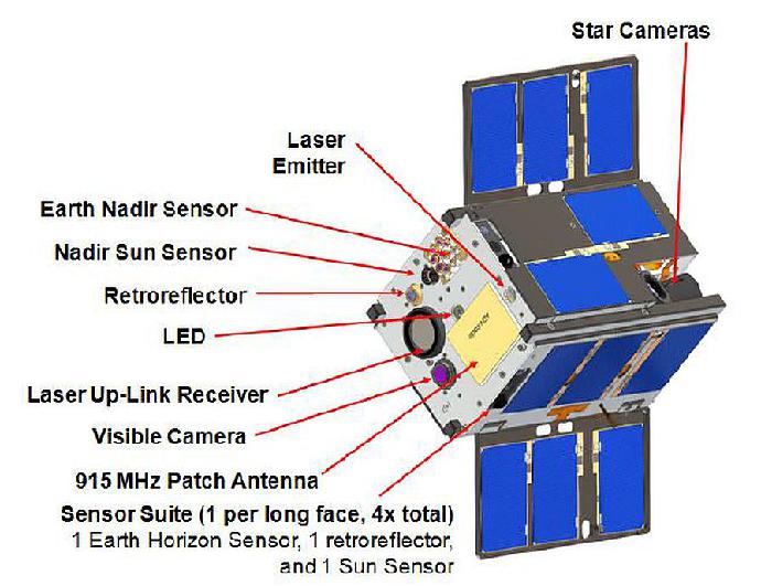
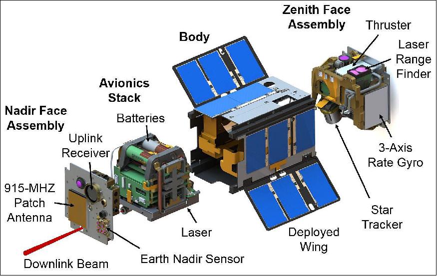
An exploded schematic view of the AeroCube-OCSD spacecraft is shown in Figure 4. There are four main subassemblies which are bolted together; the nadir face assembly, the avionics stack (which includes the laser transmitter and batteries), the body, and the zenith face assembly. Electrical interconnections use either rigid male/female sockets, or flexible circuit boards. The Pathfinder contains all of these parts, except for the thruster.
The attitude control capabilities are generally improved with each subsequent small satellite build; the plan is to obtain a sub-degree pointing accuracy for the OCSD spacecraft.
ADCS (Attitude Determination and Control Subsystem)
Since for the follow-up flight both spacecraft will fly with a wide range of orientations to support optical downlink and proximity operations, the project team incorporated six 2-axis sun sensors, four Earth horizon sensors, a two-axis Earth nadir sensor, and two sets of 3-axis magnetometers as basic attitude sensors. This combination of sensors allows continuous attitude determination with ~1º accuracy even with multiple attitude sensor failures.
The sun and Earth sensors have flown in previous Aerospace missions. Once calibrated, the sun sensors have a 0.32º root mean square (rms) error, over a 35º FOV (Field of View), in two axes. Based on flight data from multiple missions, the Earth nadir sensor has 1º accuracy in two axes. Errors typically result from using COTS optical temperature sensors that see thermal radiation from 5 to 14 µm in wavelength. Parts of this band can see all the way to the ground while other parts only see high altitude clouds that are typically cold.
The chip-scale magnetometers also have roughly 1º accuracy in two axes when instantaneous position is known and the local field is interpolated from an up-to-date magnetic field table. Magnetic field bias errors from magnetized batteries, other ferromagnetic parts, and permanent magnets in reaction wheels and other components contribute to this error.
Each spacecraft has four COTS Melexis MLX90620 infrared array sensors as an attitude-determination experiment to locate the Earth's warm limb against cold space. These sensors have a 4 x 16 array of thermopile temperature sensors that can optically read temperature with a 0.25 K (rms) temperature difference from -50º to 300 ºC at a 4 Hz rate. Each pixel has a FOV of 3.75º x 3.75º, potentially enabling nadir determination accuracy of ~0.3º when all four sensors can see the Earth's limb. These sensors provide a backup to the legacy Earth nadir sensor and should be less affected by cold, high-altitude clouds.
Fine attitude sensors: Precision pointing for laser communications using our 0.35º FWHM (Full Width Half Maximum) downlink beam width requires a 0.175º spacecraft-to-ground-station pointing accuracy that is much tighter than the ~1º pointing accuracy provided by the legacy attitude sensors. The project team added closed-loop control for tracking the laser ground station by integrating a modulated, 10 W, 1550 nm, laser uplink at the ground station, co-aligned with the telescope receiver, and a lensed photodiode receiver on the satellite to provide better than 0.1º pointing at the ground station during an overhead pass. The uplink receiver consists of a narrow-band-pass filter followed by an 18 mm diameter lens that focuses incoming light onto a 3 mm diameter InGaAs quad photodiode. Individual currents from each of the four diodes are used to generate error signals for each of two axes, while the summed output provides data. The optical uplink data rate is <10 kbit/s.
Closed-loop optical feedback is also used to aim each CubeSat laser rangefinder at the other CubeSat with better than 0.1º accuracy. The initial crude pointing direction for each spacecraft is pre-calculated on the ground as a function of time using high-precision orbital elements based on multiple, recent (within 24 hours), GPS fixes over one or more orbits. The flight-proven GPS receivers have a single point positional accuracy of ~20 m, resulting in instantaneous in-track and cross-track positional of about 10 m when using multiple GPS fixes over an orbit, high precision orbit fitting, and uploaded pointing tables. At an inter-satellite range of 200 m, a 10 m error for each spacecraft results in a maximum angular pointing error of 5.7º.
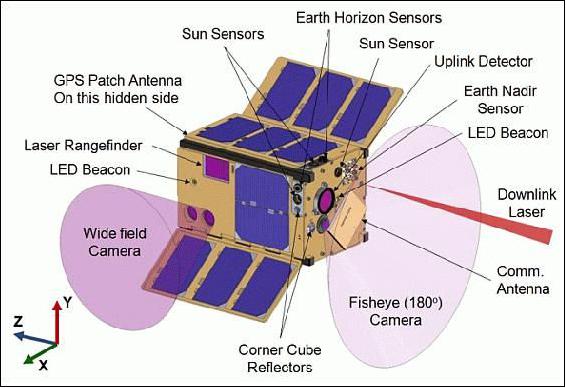
Cooperative, closed-loop tracking starts with each spacecraft aiming the +X body vector at the other spacecraft (Figure 5), using the uploaded pointing data and the current time. A red, 670 nm wavelength, LED (Light-Emitting Diode) on the +X face of the intended "target" spacecraft is turned on, and the "chase" spacecraft takes a picture using the color wide field camera on it's +X face. The 10 Mpixel color wide field camera has a 38º diagonal FOV, co-aligned with the +X surface, and the 0.3 W output LEDs have a 60º FWHM angular beam width, also co-aligned with the +X surface. For typical conditions and ranges in excess of 200 m, the +X LED will be within the camera FOV. Two more LEDs, one on the +Z and one on the –Z face, were added for potential "lost in space" conditions that can occur when the spacecraft are closer than 200 m, and/or when GPS-derived pointing vectors are "stale". This can occur if the elements are more than a few days old, or when atmospheric densities suddenly change due to a solar event.
An on-board Xilinx Spartan-6 family FPGA reads an image frame from the color camera, finds the brightest red "dot", and calculates X and Y error angles based on the dot centroid location within the imager array. With a two-pixel centroid location accuracy due to the color filter pattern on the imager, this system provides 0.016º pointing accuracy; well within the 0.09º angular beam width of the laser rangefinder.
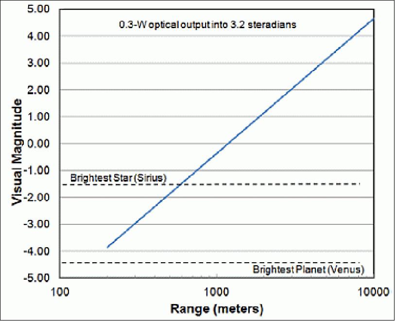
Figure 6 shows the calculated visual magnitude for the LED as a function of range, and has been verified using a ground test with a range of 800 m. The Aptina MT9D131 2MP color imager on AeroCube-4 sees stars down to 5.8th magnitude using a 16 mm focal length, f/2 lens. The 10 Mpixel Aptina MT9J003 wide field color imager on this spacecraft is one third as sensitive, but will use an f/1.6 lens to increase light collection by 50%. The 10 Mpixel wide field camera should see stars down to 5th magnitude using equivalent exposure times. Color and brightness will be used to determine whether a particular bright spot in the camera FOV is a star, planet, or red LED. Overall, an individual LED should be seen by the wide field camera out to a range of 10 km.
Open‐loop pointing is enabled through the use of star trackers that were developed based on experience obtained with simple imaging systems on AeroCube 4. Dual star trackers on each OCSD CubeSat use an Aptina MT9V022 monochrome WVGA imager with five times the sensitivity of those on AeroCube-4. These imagers are coupled to f/1.2 lenses, compared to f/2.0 for AeroCube-4, resulting in 3 times the light collection capability. A Spartan-6 FPGA reads an image frame, processes the field, and outputs a collection of star locations. These data are further processed by a 16 bit microcontroller using a star catalog to output pointing direction as a set of quaternions. The star tracker points in the +Z direction (typically zenith), while the other is canted by 40º to provide angular diversity in case stray light from the moon, sun, etc. interferes with one tracker. Star fields are imaged about once per second, and quaternion outputs are combined with more rapid rate gyro data to provide continuous attitude information with less than 0.1º error.
For robustness and power control, two 3-axis rate gyros are integrated on each spacecraft. A Sensonor STIM-210 3-axis rate gyro provides a bias stability of 0.5º/√hr, but it has a maximum power consumption of 1.5 W and needs a one hour warmup period. These devices are susceptible to helium exposure that can occur during launch vehicle preparations, so they are mounted inside their own hermetically-sealed container. This issue was discovered on AeroCube-4, using the legacy STIM-202.
Another set of rate gyros is in the VectorNav VN-100 IMU (Inertial Measurement Unit), also on each spacecraft. These gyros provide a bias stability ~10º/√hr, but the IMU consumes only 0.33 W. This IMU also contains a 3-axis set of accelerometers, a 3-axis set of magnetometers, and a pressure sensor.
Table 2 shows four different attitude control modes for optical communications, their estimated pointing accuracy, and impact on data rates. Having these four sensor modes enables a basic 5 Mbit/s optical downlink with failure of any single attitude sensor system.
Mode | Sensors | Pointing accuracy | Use |
Sunlit open loop | Sun and Earth horizon | ~0.6º | 5Mbit/s link when sunlit |
Eclipsed open loop | Earth horizon, magnetometers, and rate gyros | ~0.7º | 5Mbit/s link when eclipsed |
Star tracker open loop | Magnetometers and star trackers | ~0.1º | 50 Mbit/slink without uplink beacon |
Closed loop | Uplink receiver and magnetometers | ~0.2º | 50 Mbit/slink with uplink beacon |
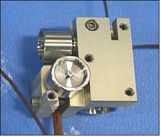
Attitude actuators include a triad of magnetic torque rods and a triad of reaction wheels. The torque rods have a magnetic moment of 0.2 Am2, they will be flight tested on the AeroCube-6 mission. They provide torques for detumbling and reaction wheel unloading. The reaction wheels, shown in Figure 7, have flight heritage on the AeroCube-4 series spacecraft. They provide primary attitude control within 0.1º with 1 mNms of total angular momentum storage and fit within a cubic volume of 2.5cm in side length. The spacecraft slew rates can be in excess of 5º/s. Note that the pointing accuracy values in Table 2 include the 0.1º attitude actuation accuracy.
EPS (Electrical Power Subsystem)
The wing surfaces and two of the rectangular side panels have three, ~1 W, triple-junction solar cells, while each of the remaining two rectangular side panels have a single, 2 W triple-junction cell. Maximum solar input power is 9.5 W, and typical orbit-average power in the expected orbit is 4.5 W.
As built, the pathfinder CubeSat has a mass of ~2.5 kg and consumes under 2 W during most of the mission life. During laser communication engagements, which are expected to last no more than 3 minutes, the spacecraft will consume an additional 40 to 50 W for operation of the 10 W optical transmitter. The wing surfaces and two of the rectangular side panels have three, 1 W, triple‐junction solar cells, while the remaining two rectangular side panels have two, 1 W triple‐junction cells. Maximum solar input power is 9.5 W, and typical orbit‐average input power is expected to be 4.5 W. Two COTS 18650 size high‐energy lithium ion batteries with a total capacity of 14 W hr provide spacecraft power during eclipse, and two COTS high‐current 18650 size lithium ion batteries provide over 50 W to the laser transmitter during optical downloads. The high‐current batteries are a type typically used to power handheld portable drills and other power tools.
Launch
The pathfinder satellite (AeroCube-7A) was launched on October 8, 2015 (12:49:30 UTC) as a secondary payload — and will be followed by a pair of Block‐II satellites (AeroCube-7B and -7C) in 2016. - The primary mission was the classified NROL-55 of NRO (National Reconnaissance Office) with the satellites: Intruder-11A and -11B of the US Navy, referred to as USA-264 [NOSS (Naval Ocean Surveillance System)]. The launch site was VAFB (SLC-3E) and the launch vehicle was Atlas-5 EELV-401 configuration with Centaur ABC (Aft Bulkhead Carrier) of ULA. 5) 6) 7)
The Atlas V rocket also delivered 13 GRACE (Government Rideshare Advanced Concepts Experiment) CubeSats to orbit. The nine NRO-sponsored CubeSats and four NASA-sponsored CubeSats were mounted to the ABC (Aft Bulkhead Carrier) located on the back end of the Centaur upper stage.
Orbit
Near-circular orbit, altitude of ~1100 km, inclination = 63.4º.
Secondary Payloads of NROL-55/GRACE (Government Rideshare Advanced Concepts Experiment) - Sponsored by NRO and NASA
• AeroCube-7A -OCSD, a 1.5U CubeSat of The Aerospace Corporation, El Segundo, CA.
• AeroCube-5C, a 1.5U CubeSat of The Aerospace Corporation, El Segundo, CA.
• Three SNaP-3 (SMDC Nanosatellite Program-3), 3U CubeSats of the U.S. Army SMDC (Space and Missile Defense Center), Redstone Arsenal, AL.
• Two PropCube nanosatellites (2U) of Tyvak and SRI International, Menlo Park, CA.
• Two SINOD-D 2U technology demonstration CubeSats (SINOD-D 1, SINOD-D 3) of SRI International
• ARC-1 (Alaska Research CubeSat-1), a 1U CubeSat developed by students of the University of Alaska, Fairbanks.
• BisonSat, a 1U CubeSat of Salish Kootenai College, Pablo, Montana, USA.
• Fox-1, a 1U CubeSat of AMSAT (Radio Amateur Satellite Corporation).
• LMRST-Sat (Low Mass Radio Science Transponder Satellite), a 3U CubeSat of NASA/JPL (Jet Propulsion Laboratory).
Mission Status
• August 2019: An opportunity arose to demonstrate optical crosslink pointing between two CubeSats in LEO using spacecraft not specifically designed for that purpose. The AeroCube-7 spacecraft, designed for optical downlinks as part of the Optical Communication and Sensor Demonstration mission, was tasked to point its communications laser at the ISARA (Integrated Solar Array and Reflectarray Antenna) spacecraft to demonstrate the capability of one CubeSat to track another in LEO. The ISARA spacecraft, which does not carry a data receiver, but does carry a short-wave infrared camera (SWIR) as part of the CUMULOS payload, was tasked to track the AeroCube-7 spacecraft and use the SWIR camera to record the OCSD laser. The SWIR images were downloaded over an RF channel and used to evaluate the pointing and tracking of both spacecraft. Two successful tests of crosslink pointing were completed between AeroCube-7 and ISARA, providing a demonstration in principle of the capability, and laying the groundwork for more refined experiments that will use this technique for on-orbit measurements of beam profiling. Further tests between AeroCube-11 and ISARA are also in preparation to demonstrate crosslink pointing in a more-challenging orbital configuration. 8)
Experiment
- A total of four spacecraft, all CubeSats, were involved in various parts of this experimental effort. However, none of the four were designed with this experiment in mind; this was an experiment of opportunity using spacecraft capabilities designed for other purposes. The Optical Communication and Sensor Demonstration program supported the development and launch of two 1.5U CubeSats, AeroCube-7B and AeroCube-7C, also known as OCSD-B and OCSD-C, designed to demonstrate optical downlinks from LEO.
- These satellites each carry a single-stage Yb-fiber master-oscillator power-amplifier (MOPA) laser system designed to produce from 2 to 4 W output at 1064 nm wavelength, and capable of being modulated at data rates of at least 200 Mbit/s. The laser in OCSD-B has a fixed beam divergence of 0.06 degrees FWHM while the laser in OCSD-C has a fixed beam divergence of 0.15 degrees FWHM. The lasers are hard mounted to the satellite bodies and have no secondary beam steering system, so laser pointing is controlled entirely by controlling the spacecraft attitude. The spacecraft attitude-control system (ACS) includes a number of coarse attitude sensors (Earth nadir, Earth horizon, magnetometer, and sun sensors), a pair of custom designed star cameras for fine attitude sensing, two three-axis rate gyros, three orthogonal reaction wheels, and three orthogonal magnetic torque rods. The ACS has been characterized in flight testing and has demonstrated RMS pointing errors typically below 0.02 degrees for tracking a ground-station location. The spacecraft also incorporate GPS receivers that can be used to develop high-precision orbit ephemeris information. The spacecraft and lasers are further described by Rose. 9) These two spacecraft were launched on November 13, 2017 and deployed from Cygnus OA-8E on December 6, 2017 into an orbit with a nominal altitude of 450 km and an inclination of 51.6 degrees.
- The R3 spacecraft (also known as AeroCube-11B, or AC-11) is a 3U imaging-technology demonstrator with a primary mission of exploring pushbroom imaging in a CubeSat. The R3 spacecraft bus is closely based on the design of the OCSD bus, with mostly identical avionics. The ACS incorporates the same suite of sensors and rate gyros, but uses larger reaction wheels and magnetic torque rods to compensate for the greater moments of inertia in the 3U bus. While OCSD was a laser downlink technology demonstrator, the R3 satellite, which launched on December 15, 2018, incorporates a laser transmitter as an operational data downlink channel. The laser is functionally identical to the lasers in the two OCSD spacecraft but incorporates some structural changes required for integration into a slightly different bus. Like OCSD, the R3 laser is body mounted and beam pointing is controlled by the spacecraft ACS. The beam divergence in the R3 laser is 0.10 degrees. This spacecraft is described in more detail by Pack2. 10)
- The ISARA spacecraft is a 3U communications technology demonstrator that had as its primary mission a test and demonstration of a deployable high-gain Ka-band antenna. The satellite also carried an auxiliary payload, the CubeSat Multispectral Observation System (CUMULOS), which consists of three co-boresighted cameras, one operating in the visible spectrum, one in the short-wave infrared (SWIR) and one in the longwave infrared (LWIR). Neither the visible camera nor the LWIR camera has sensitivity to the OCSD laser wavelength, but the SWIR camera is sensitive to the 1064-nm wavelength of the OCSD lasers. The ISARA bus is essentially identical to the R3 bus, including all the ACS components. However the ISARA bus does not have a communications laser on board, and data download is via a 915-MHz UHF radio. The CUMULOS SWIR camera is a FLIR Tau SWIR 25 equipped with a vented lens from Stingray Optics. The sensor is a FLIR InGaAs array with 640 by 512 pixels, and is sensitive over the spectral range from 900 to 1700 nm, which includes the 1064-nm wavelength of the OCSD and R3 lasers. The ISARA spacecraft and CUMULOS payload are described in more detail by Hodges 11) and Pack (Ref. 10). 12)
Orbital Dynamics
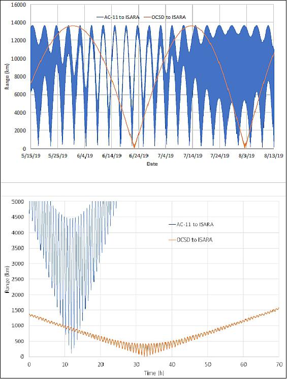
- The two OCSD spacecraft and the ISARA spacecraft were all deployed from the same launch vehicle on December 6, 2017 and started out in nearly identical orbits. Since then, the two OCSD spacecraft, which have nearly identical ballistic coefficients, have been conducting proximity operations experiments using a combination of variable drag and an experimental propulsion system 13) and so remain very close together in orbit. ISARA, on the other hand, does not have a propulsion system, and has a ballistic coefficient substantially smaller than that of the OCSD spacecraft, so has experienced more orbital decay. As a result, by the time these experiments started, a little over a year after deployment, the orbit of ISARA was a few km lower than that of OCSD. Consequently, the orbital period of ISARA was a few seconds shorter than OCSD, and ISARA, although in the same orbital plane as OCSD, would lap OCSD about every two months. For most of the time, ISARA is below the horizon relative to OCSD, but approximately every two months, for a period of several days, the three spacecraft were in range of one another.
- The R3 spacecraft, which was launched a year later than the other three, is orbiting at about 500 km altitude and 85 degrees inclination. This orbit brings it within range of ISARA in a series of passes in sequential orbits in a pattern that repeats about every 4.5 days. Figure NO TAG# shows representative plots of the ranges between the various satellites as a function of time.
- Before beginning the experiments, we evaluated the minimum and maximum ranges over which the crosslink was possible. The maximum range would be limited either by the minimum signal strength detectable in the SWIR camera, or by the shape of the orbits causing the beam path to intersect the Earth's limb. The minimum range would be limited either by the uncertainty in orbit determination (recall that the beam spot size is smaller at shorter ranges, but the orbit uncertainty is independent of range), or by the potential for the laser beam to damage the camera at the high beam flux possible at very short ranges.
- The minimum signal strength detectable by the SWIR camera depends on camera settings and is difficult to define clearly. Thus, we chose to approach it by comparing the expected signal strength at maximum possible range as limited by orbital dynamics to the signal strength clearly observed in existing starfield images acquired by the SWIR camera. The star Alpha Tau (Aldebaran), which was clearly visible in previous images acquired by this SWIR, has a spectral energy distribution that was modeled according to the method of Rudy6. For this analysis, we integrated this spectral energy distribution over the spectral range of the SWIR camera, yielding a total flux of about 14 nW/m2 in Earth orbit.
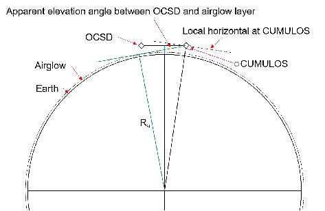
- For two satellites in circular orbits at 450 km altitude, and assuming a spherical Earth for simplicity, the straight-line beam path between them would be tangent to the surface when they are separated by about 4875 km. At greater separations the beam path would intersect the surface, so this number represents the maximum link distance in principle. In practice, however, it would be very challenging to see the laser at this range because of atmospheric distortions, as well as infrared background visible from the Earth's surface and atmosphere. A practical lower limit for the altitude at which the beam can skim the atmosphere is the infrared airglow layer visible in the SWIR camera when viewing the Earth's limb. This layer typically falls between 90 and 100 km altitude. Selecting 100 km as the minimum tangent altitude gives a maximum range of about 4310 km between the two satellites. For the case of R3, where the receiver is at 450 km and the transmitter at 500 km, the maximum range goes up to about 4460 km. At shorter ranges, the laser beam will have an apparent elevation angle above the airglow layer that is determined by the separation between the spacecraft. Figure 9 illustrates the relevant geometry.
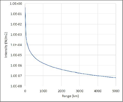
- The expected signal strength is a function of range, pointing accuracy, and laser beam properties. The laser beams are profiled in the laboratory prior to launch. For OCSD-B, the beam has a Gaussian profile with a beam divergence of 0.06 degrees FWHM1, or 0.051 degrees when measured at the 1/e2 radius. The centerline beam flux I is a function of distance and is given by I=2P/πw2, where P is the total beam power and w is the 1/e2 radius of the beam at the range of interest. Figure 10 shows the expected centerline beam flux for the OCSDB laser as a function of range. At the maximum possible crosslink range of 4310 km, the centerline flux is about 85 nW/m2, or a factor of six higher than the total IR flux from Alpha Tau. As such, OCSD-B should be clearly visible to the SWIR camera even at the maximum possible crosslink range. OCSD-C has a beam divergence of 0.15 degrees FWHM, so will have a lower centerline beam flux. Nevertheless, even at 4310 km, the OCSD-C centerline flux should be above 13 nW/m2, and so should be clearly visible to the SWIR camera. The laser in the R3 spacecraft has a beam divergence of 0.10 degrees FWHM, intermediate between the two OCSD lasers, and the expected centerline flux will be about 29 nW/m2 at the 4460 km maximum range possible between R3 and ISARA.
- We also estimated the minimum range at which there is no risk of damage to the SWIR (in operation) or to either of the other two cameras (which would be exposed to the beam, although not in operation). For OCSD-B, which has the highest centerline beam flux, this range was well under 1 km, so would not be a limitation on the experiment.
Experimental Procedure
- Conceptually the experiment is very simple; one of the transmitting satellites points its laser toward the ISARA spacecraft while the CUMULOS cameras on ISARA are pointed at the transmitting spacecraft and the SWIR camera acquires images. In practice, there are a few steps along the way.
- The first step is to identify opportunities. This involves looking ahead at the forecast orbital positions of the satellites and considering not only range but also other constraints including that the crosslink operations work best if both satellites are in eclipse. Since this is a mission of opportunity, the crosslink operations are also constrained by the priority of other satellite operations.
- Once an opportunity has been identified, the satellites will collect GPS fixes for at least two orbits within 24 hours in advance of the experiment to obtain precision ephemeris information. The satellite position information available from published ephemeris data (TLEs) carries an uncertainty of a few thousand meters, which is large compared to the laser spot size at shorter ranges. With the on-board GPS data, the position uncertainty of the satellites can be reduced to a few meters, which is well below the laser spot size, even at ranges as short as 50 km.
- The precision ephemeris is used to develop a detailed pointing plan for both spacecraft as a function of time. This is necessary because both spacecraft are pointing open-loop - there is no mechanism for either spacecraft to track the other in real time, so they operate independently, with pointing based solely on the expected positions of both spacecraft. The pointing plan is translated into a set of command sequences, including not only pointing but activation of both the laser and camera. The command sequences are then uploaded to both spacecraft in advance of the expected opportunity. After the scheduled event, as the spacecraft pass over ground stations, the telemetry and images are downloaded for analysis.
Results
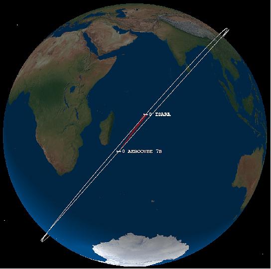
- The first successful run of the experiment took place on 9 January 2019, when the ISARA and OCSD-B spacecraft were over the western Indian Ocean (Figure 11), separated by a range of 1995 km. The direction of motion in Figure 11 is from southwest to northeast, and ISARA is leading OCSD-B, so the images are looking back approximately along the orbital track.
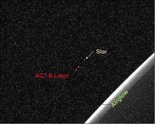
- During this run, the attitude control system of the OCSD-B spacecraft was commanded to track the ISARA spacecraft, with the laser operating at a constant output. The CUMULOS payload was pointed at the OCSD-B spacecraft and a series of eleven images were acquired at intervals of approximately 3 seconds. During this run, the camera exposure settings were adjusted between frames through a series of steps with the goal of determining optimum camera settings for future runs. Figure 12 shows the first image of this series. One challenge with using a COTS SWIR camera is that this type of camera is known to be susceptible to radiation-induced hot pixels in LEO. This is clearly evident in Figure 12; almost all of the bright points seen in this figure are hot pixels. Since hot pixels tend to be isolated single pixels (surrounded by black pixels), the two obviously brighter points of light, which spread across multiple pixels, can be identified as a star and as the OCSD-B laser.
- The camera point of view is tracking the OCSD laser as the two spacecraft orbit the Earth, so the position of the laser will not change over successive images, while the apparent position of any stars will. This is evident in Figure 13 which shows the result of averaging all eleven images and then subtracting one image to remove most of the hot pixels (which change little from frame to frame). The two stars in the field of view appear to move toward the Earth's limb in successive images due to orbital motion. They also appear to change in brightness due to changes in camera settings. The Earth's limb, on the other hand, does not appear to move between successive frames because the orbits are approximately circular and the perspective relative to the Earth does not change from frame to frame (see Figure 9).
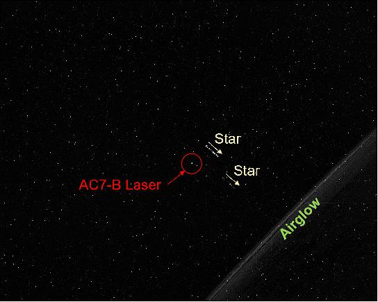
- Further image processing makes it possible to remove nearly all hot pixels. Figure 7 shows the results of combining two successive images by enhancing the contrast, increasing the brightness, and subtracting the second image from the first. The result of this is several pairs of bright and dark spots with a constant offset corresponding to orbital motion, where the bright spots are stars seen in the first image and the dark spots are locations of the same stars in the second image. This approach makes it possible to unambiguously determine the locations of a moderate number of stars in the image which, when compared to an infrared sky map, are easily identified, as indicated in figure 7. The difference between the infrared sky and the visible sky is brought out by the presence in this image of some rather obscure stars along with the absence of some stars that are fairly bright in the visible sky. For example, the star Alnair (Alpha Gruis), which has a visible magnitude of 1.7 can be found in the image only by reference to nearby stars. In contrast, the nearby star Pi Gruis, which has a visible magnitude that varies between 5.3 and 7, is clearly identifiable in the image.
- The second experimental run with OCSD-B occurred on 15 March 2019, with the two satellites over the western Pacific Ocean, separated by a distance of 2292 km. Again, ISARA is in the lead, looking back along the orbital track to OCSD in a generally southwesterly direction. This experiment was intended as a pathfinder for beam-profile measurements. As with the previous test, ISARA was programmed to have the CUMULOS payload track the location of the OCSD spacecraft and acquire images. In this case, the SWIR images were acquired at ten-second intervals with constant camera settings. While the images were being acquired, the OCSD spacecraft was programmed to slowly sweep the laser beam across the location of the ISARA spacecraft. The intention was to measure beam intensity at the camera as a function of time by evaluating the images, then correlate the signal strength with the laser pointing to estimate beam profile. The experiment was qualitatively successful in that the beam could be clearly seen increasing and decreasing in intensity as it swept across the camera. However, the camera exposures were too long and the laser saturated the pixels in most of the exposures, making a quantitative measurements of signal strength impossible. In addition, the camera frame rate was too slow compared to the slew rate of the laser, leaving only five images in which the laser was visible.

- Figure 15 shows an image of the OCSD laser as well as one star acquired in the second run. Although the field of view included the star Canopus, the brightest visible star in the southern hemisphere, a careful review of the orbital ephemeris data indicated that the star visible in the image is actually R Doradus, which is the brightest infrared star in the southern hemisphere but has a visible magnitude that varies between 4.8 and 6.6. Canopus, which has a visible magnitude of -0.7 but is not nearly as bright in the IR, is also very faintly visible near the top of the frame. Because of the brightness of the OCSD laser, the required SWIR camera exposures are very short and only a few of the brightest IR stars can be seen. In the two successful runs to date we were fortunate to have stars clearly visible in the frame - in much of the sky there are no IR stars bright enough to be seen at the camera settings used to acquire the images of the OCSD-B laser.
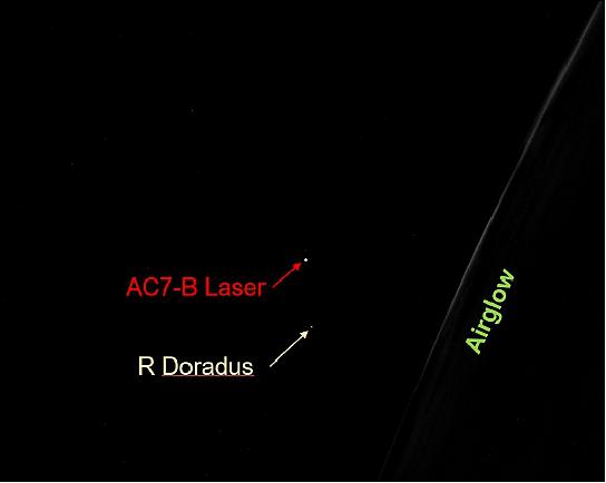
- One additional positive result that came out of the second experiment run was the observation that the image of the OCSD laser was centered on the same SWIR camera pixel as in the first run. This indicates that ISARA is capable of tracking the OCSD spacecraft with a precision at least comparable to the single-pixel field of view of the SWIR camera, which is about 0.1 degrees.
Future Work
- Two experimental runs were conducted with AC-11 as the transmitter. This is a somewhat more challenging test since AC-11 is in an orbit inclined about 25 degrees relative to the orbit of ISARA, meaning that there will be significant relative motion between the satellites and they will have to slew to keep the laser beam and cameras aligned with one another. In both runs, however, no image data was acquired. Telemetry indicated that AC-11 performed the programmed attitude maneuvers and turned on the laser. However, the command sequence on ISARA failed to initialize for reasons that are still being evaluated. As of this writing, further attempts at crosslink pointing using AC-11 and ISARA are planned.
- Three additional improvements are also planned for the beam-profile measurements. First, additional experiments will be used to refine the camera exposure settings to ensure that we do not saturate the pixels at peak exposure. Second, a code modification to the ISARA SWIR camera controller will allow subframing. The results to date indicate that ISARA can point well enough that we do not need a full frame to ensure that the laser is captured by the camera. Since the downlink bandwidth on ISARA is very limited, the reduction of the frame size by one to two orders of magnitude will allow us to acquire ten to 100 times more frames. Third, we will adjust the OCSD slew rate and the SWIR camera frame rate to ensure that we get far more than five exposures as the beam sweeps across the camera. The increase in the number of images as the intensity ramps up and down will give a much higher spatial resolution on the laser beam profile measurement.
- In summary, the goal of this mission of opportunity was a practical demonstration that one CubeSat in orbit can track another with sufficient precision to achieve an optical crosslink. Although no data was transferred (nor was there any intention to pass data), the exercise demonstrated that crosslink pointing and tracking is possible. Further, a pathfinder test indicates that optical crosslinking has the potential to provide a means for on-orbit optical beam profile measurements that will be free of atmospheric distortions. Future tests are intended to demonstrate optical crosslink pointing with more challenging orbital dynamics, and to obtain quantitative beam profile measurements.
• August 2016: The OCSD-A spacecraft was launched with unfinished software modules since the process for uploading software updates had been previously demonstrated over 350 times across 9 different spacecraft. This time, however, the software upload to the attitude control processor experienced an on-orbit anomaly that rendered the attitude control system inoperative. Unfortunately, the attitude control processor also controlled downlink laser activation for safety reasons, so both the attitude control and laser downlink systems were disabled. In addition, all attitude sensors, actuators, and the laser rangefinder were disabled. 14)
- The flight anomaly was traced to a change in processor partitioning, without a change in the uploading sequence. Flight uploads typically occur incrementally over several ground contact periods, and data blocks are uploaded sequentially. In our case, a new processor partitioning scheme required a non-sequential upload; not a sequential one. Between ground contacts, the AeroCube-OCSD-A vehicle executed a regularly scheduled power-cycle, and this power-cycle re-booted the ACS processor into a partially, but not fully, updated program which prevented proper initialization. The power-cycle re-boot was not included in our pre-upload ground simulation, and we ended up with a "bricked" processor; an inert device that would not accept further updates. Unfortunately, this processor handled attitude sensor and actuator data, leaving the spacecraft without active attitude control.
- Flight data: Attitude sensors, including magnetometers, sun sensors, the Earth nadir sensor, and two different rate gyro triads, plus actuators such as the reaction wheels and magnetic torque rods, were tested for basic operation during the initial spacecraft checkout phase. These operated as expected. Uploading of new attitude control software such as the B-dot despin routine occurred next. This is when the attitude control processor became unresponsive. — Operational post-failure systems included the power system (new), camera image processing board (new), GPS receiver, a software defined radio transceiver (new), the primary communications transceiver, the command and control system, a distributed temperature monitoring system, two star tracker cameras (new), the wing deployment system (new) and the star tracker baffle deployment system (new). The software defined radio is a redundant radio that offers download rates up to 500 kbit/s. All of these systems operated as expected, thus validating their design and testing procedures. AeroCube-OCSD-A is power positive, thermally stable, and in daily contact with our ground stations. It has reduced risk for the upcoming AeroCube-OCSD-B&C flights, but not by as much as we had originally planned. Nevertheless, the project learned important lessons.
Passive rotation rate damping mechanisms such as Eddy current generation in the aluminum hull and flexing of board stacks, the deployed wings, etc., have slowly despun the spacecraft over weeks and months. This allowed testing of the proximity and star tracker cameras with spacecraft rotation rates below 1º/s. Figure 16 shows an image downloaded from the 10 Mpixel proximity camera mounted near the bottom right corner of the right body panel shown in Figure 2. This image is centered near Quinhagak, Alaska and includes parts of the Togiak and Yukon Delta National Wildlife Refuges. Ground resolution was only 305 m due to the small lens aperture. This was an image of opportunity; the proximity camera happened to pointing at the Earth when we commanded an image acquisition.

- Star tracker images were accessible through the camera image processing board, so the project was able to download images and process them on the ground to verify star tracker operation. These star trackers enable 0.02º angular determination accuracy that will be needed in the upcoming — AeroCube-OCSD-B&C demonstration flights, so this was an important test. We took multiple stellar images before and after wing deployment, which produced a decrease in rotation rate from 0.97º/s to 0.80º/s.
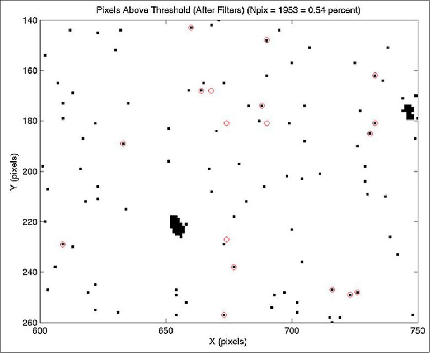
Figure 17 shows part of a processed image in negative form taken on Dec. 2, 2015, before wing deployment. This was about 6 weeks after launch. The large black blobs are stellar tracks while the individual dots are either hot or warm pixels. Hot pixels are much brighter than the median level while warm pixels are only a few counts above the median. Maximum counts per pixel is 255, and the imagers have a 760 x 480 pixel format. About 1450 single dots appear in whole image, which is much larger than the 381 hot pixels measured during ground tests. These hot pixels are indicated by red circles in Figure 17. Radiation is most likely creating new hot pixels; we will monitor the number of these pixels in each imager as a function of time. No warm pixels were measured during ground tests.
Post wing deployment measurements showed that stellar magnitudes down to 4.5 provided reliable targets with a SNR (Signal-to-Noise Ratio) of 3 or better using a 150 ms exposure. Stars down to magnitude 5 were detectable at SNR=2, and the on-orbit background noise level was 10 counts per pixel. Note that Figure 17 shows only 5% of the full image frame. Monte Carlo analyses using 500 random attitudes have shown that 3 or more stars, the number needed for a 3-axis attitude fix, are available with SNR>=3 at least 55% of the time at the angular rotation rate of 0.8o/s. With a lower SNR of 2, that increases to 86% of the time. At lower rotation rates, dimmer stars become visible. At a 0.1º/s rate, our star tracker can see 3 or more stars with an SNR>=3 98% of the time when sunlight and Earthshine do not interfere. Even higher levels of availability are possible using both star trackers since they observe different parts of the sky. Overall, our star trackers have proven that they can provide the needed attitude determination accuracy for the upcoming AeroCube-OCSD-B&C flight demonstrations.
• Oct. 9, 2015: NASA and The Aerospace Corporation have received confirmation of the OCSD CubeSat in orbit. 15)
Sensor Complement
Optical Downlink Transmitter
The downlink laser is based on an amplitude-modulated 1064-nm wavelength master oscillator (the seed laser) with a fiber output at ~10 mW average power, followed by two stages of fiber laser amplification. The polarization-maintaining ytterbium-doped fiber amplifier stages take this 10 mW level seed output power first to 0.3 W, and finally, 6 W. Figure 18 shows a schematic of the transmitter, which is designed to operate over a temperature range of 10-50ºC.
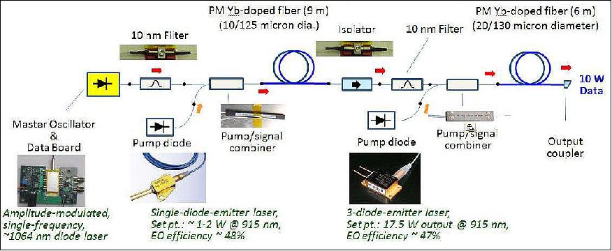
Figure 19 shows a photo of two laser transmitters in the clean room awaiting assembly, and Figure 20 shows a photograph of one ~9 x 9 x 2.5 cm laser transmitter during spacecraft fit checks. The star trackers and MEMS gyro shown on the bottom right in Figure 20 are connected to a different assembly than shown in Figure 4, but when assembled, reach the relative position shown. This is a dense spacecraft. The laser components are mounted to an anodized aluminum base plate with fiber windings on both sides. Nusil CV-2946 and heat conducting epoxy were used to transfer heat generated in the laser diode pumps and gain fibers, respectively, into the aluminum mounting structure that also serves as a heat sink. 16)
A small lens, the output optic placed after the 2nd amplifier stage, was adjusted to yield the desired output divergence. In our case, we used a 0.3º FWHM angular divergence to match the required 0.15º (3σ) spacecraft pointing uncertainty. The laser beam exits to the left in Figure 7. As configured, our laser is capable of delivering in excess of 10 W of optical output at 1064 nm at a wall plug efficiency of 25%. The project de-rated it to 6 W in order to boost reliability for the Pathfinder laser downlink.
The largest component in the laser assembly, other than the aluminum structure/heat sink, is the second stage isolator. Optical isolators use Faraday rotation, and Faraday rotation of plane-polarized electromagnetic waves requires a magnetic field. Unshielded, these fields can add to the magnetic moment of the spacecraft, thus making attitude control harder as the local magnetic field varies over an orbit. Unshielded magnetic fields also disturb the Earth's local field, making on-board magnetometers much less accurate. The project therefore encapsulated the optical isolators in µ-metal shields.

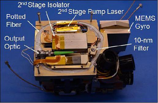
The avionics stack and batteries are below the laser shown in Figure 20 (see Figure 4). The star trackers and MEMS 3-axis gyro are part of the zenith end assembly.
Uplink Beacon Detector
Closed-loop pointing at the optical ground station is accomplished using an uplink laser, bore-sighted with the receive telescope, in the ground station. The uplink receiver, as illustrated in Figure 4, has a 2.5 cm diameter port on the nadir face. A 10 nm wide band pass filter passes the 1 to 10 kbit/s, on-off keyed, 1550 nm wavelength uplink beacon signal to a 18 mm diameter lens that focuses incoming light onto a quad photodiode. It can accommodate a 1º off-axis input error which is compatible with attitude control errors when the star trackers are not used. The quad photodiode and associated electronics generate pointing error signals for the on-board attitude control system. The closed-loop pointing system can point within 0.02º; well within the 0.15º required for the Pathfinder.
Uplink data are collected by summing the quad photodiode signals together. When no data are present, the uplink beacon is a square wave with 50% duty cycle. When data are present, the overall duty cycle is still 50%, but the high and low signal periods will constantly vary.
Star Trackers
All three of the OCSD CubeSats (Pathfinder plus two flight units) can operate in either closed-loop or open-loop tracking mode. A star tracker is the only way to obtain the 0.15º or better pointing accuracy we need for the laser downlink using open-loop pointing. In open-loop mode, the ground station becomes simpler because it does not need an uplink laser beacon.
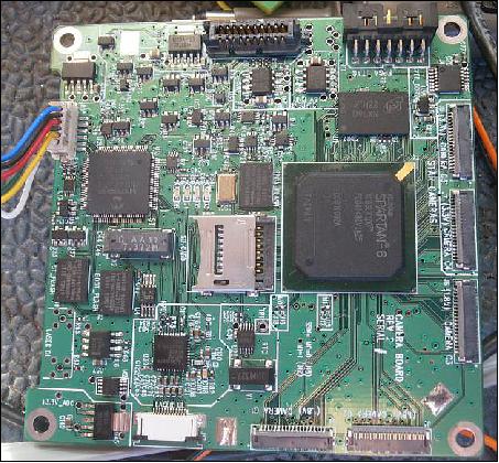
The star tracker main board, shown in Figure 21, is part of the avionics stack illustrated in Figure 4. This board is actually an image-processing board that supports star tracker operation using two CMOS monochrome image sensors, and image/video processing of three more color CMOS image sensors. It contains two main processors: a low-power PIC24FJ256 microcontroller and a Spartan-6 LX100 FPGA. The FPGA can also act as a general-purpose camera for both photos and video, storing raw or JPEG-compressed frames to external flash memory. The PIC receives commands from the main flight computer, controls power to other devices on the board, loads the FPGA firmware, and matches the filtered image against a catalog of stars to solve for attitude when required.
When used as a star tracker, the FPGA interfaces with up to five image sensors, captures and timestamps raw image data, and applies the star-tracker image filters. Raw image data is buffered in a 128 MB DDR2 RAM (Double Data Rate 2 Random Access Memory). The FPGA can also act as a general-purpose image processor for both photos and video, storing raw or JPEG-compressed frames to flash memory. Note the silver SD memory card slot in the center of the board, just to left of the Spartan-6 FPGA, for flash memory storage.
The two star trackers are shown in Figure 22 with their light baffles extended. The baffles are deployed using "muscle" wire that allows resetting and hundreds of ground tests using the same hardware; reliability is vastly improved over one-time melt wire approaches. Each camera assembly contains a lens, mounting hardware, and an image sensor daughter card, with multiple designs to serve various mission requirements. Up to five image sensors can be connected to the mainboard using fine-pitch flexible flat cables that provide adequate cable-routing flexibility without the complexity and power consumption of a serializer/deserializer connection.
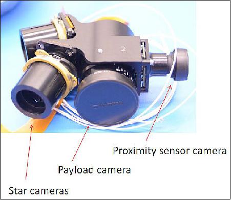
The star trackers use Aptina MT9V032 CMOS image sensors (Grayscale, 752 x 480 pixels). Two star trackers are used to provide resilience against image flares due to the sun, Earth, and moon; the one with the darkest background image can be selected at any given time. If both trackers become temporarily blinded, the low-drift rate MEMS gyros can be used that can provide the required ~0.15º attitude determination accuracy for at least 10 minutes. Figure 23 shows a photograph of the camera assembly that includes the two trackers, an Earth imaging camera, and a side-looking camera for proximity operations.
The star trackers have identified stars down to 5.8th magnitude using a 0.1 s exposure in ground tests. Onboard image processing using the FPGA includes "hot" pixel blanking, row-, column-, and global-median filtering, sliding window median filtering, circular mask filtering, and adaptive thresholding.
Another feature integrated into the star tracker processor board is the ability to track stars or other objects of a particular color. This feature will be used to aim a "tracker" OCSD CubeSat at a "target" OCSD CubeSat during proximity operations for the two final flight units. Intersatellite pointing angles up to 48 hours in advance will be calculated on the ground using downloaded GPS data and high-accuracy ephemerides based on that data. These pointing angles will be uploaded to one or both satellites for crude pointing at each other. On-board color cameras, like the side-pointing camera shown in Figure 23, will take images of the target satellite, which will turn on one or more blue LEDs, and the attitude control system will center that satellite in its field-of-view. One LED is on the nadir face, as shown in Figure 3, one is on the zenith face, and one is on the face with the rangefinder (top body surface in Figure 4). These blue LEDs have a 300 mW optical output into roughly one steradian of solid angle, and should be visible out to a range of greater than 10 km using the side-looking color camera.
Once the target is centered within the field-of-view of one of the color cameras, the attitude control system can execute one or more 90º rotations, if needed, to point the laser rangefinder at the target. The laser range-finder will then be able to determine intersatellite distance to within 1 m, out to a range of 2 km. Laser retroreflectors on each spacecraft body surface enable this range using the low-power Jenoptik DLEM-SR rangefinder.
Laser rangefinder: The previous discussion outlined the process for aiming each +X spacecraft surface at the other spacecraft with an error of less than 0.02º. Once aligned, either spacecraft can use an on-board Jenoptik DLEM-SR laser rangefinder to measure the intersatellite range to 1 m accuracy. The GPS-based measurements are good to 10 m error for each spacecraft, so optical ranging improves range accuracy by an order of magnitude. These range data will be used by the high-precision orbit ephemeris fitting program to further refine orbit accuracy.
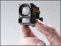
Figure 24 shows a photograph of the DLEM-SR rangefinder while Figure 3 shows its location on each spacecraft. This unit has dimensions of 5.4 cm x 2.2 cm x 3.4 cm and consumes less than 2 W during operation. It uses a 1550 nm pulsed laser with a 1.6 x 1.8 mrad (0.09º x 0.10º) beam width to provide range out to 5 km. 17)
Water Thruster
Note: This device is not used for the pathfinder mission but will be used in the follow-up mission of two 1.5U CubeSats.
The propulsion requirements call for ~3 m/s of delta-V to bring two CubeSats to within 1 km of each other and to perform 30 sets of proximity operations. We over-sized The propulsion system is over-sized to 10 m/s to account for inevitable missteps in orbit control and to allow for multiple tests of collision avoidance maneuvers. If all CubeSats had the ability to maneuver away from a potential collision with another space object, there would less concern in the overall space community about the rapidly increasing numbers of CubeSats on orbit.
The project's chief concern was to design and build a propulsion system that had low mass, low power requirements, and a minimum number of ground tests and documentation required for integration into a P-POD. Aerospace has flown cold gas and solid rocket thrusters on spacecraft ejected by the U.S. Space Shuttle, and the project wanted to minimize the costs associated with propulsion system integration and safety requirements.
The easiest propulsion systems to flight qualify are those with low thrust (this prevents significant changes in orbital elements that can confuse ground-based tracking systems), have minimum explosion hazard during launch, and use non-toxic, non-reactive propellants. The project team ended up borrowing a propulsion system from the ancient Greeks; Hero's steam thruster. Water has a low molecular weight, thus offering a roughly 100 s specific impulse at room temperature, a vapor pressure significantly below 1 atmosphere at room temperature to eliminate the use of pressure vessels, is relatively inert with respect to most launch vehicle components, and is non-toxic in the quantities required (about one ounce, or a full shot glass). A 1st century, or even 18th century "steam punk," thruster actually makes sense for 21st century CubeSats.
A water thruster has flown on the STRaND-1 CubeSat of USSC (University of Surrey Space Center); namely the WARP (Water Alcohol Resistojet Propulsion) drive.18) The OCSD project decided to forgo the alcohol in order to minimize flammability hazards on the launch vehicle, not to mention the laboratory. Alcohol or other compounds are typically added to water to lower the freezing point and prevent tank and tubing rupture. The OCSD approach is to use a propellant management system that holds the water, or ice, within an expandable volume that cannot touch the propellant tank walls. Freezing of water does not compromise the propulsion system structure.
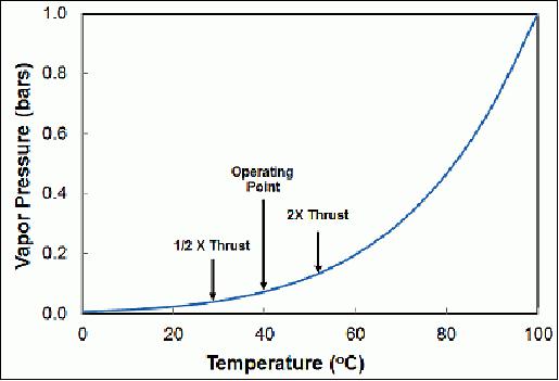
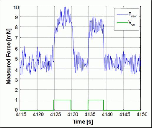
A key challenge in designing a water thruster system for a 1.5U CubeSat is to provide the required level of thrust at low vapor pressure. Figure 25 shows the vapor pressure of water as a function of temperature. The team intends to operate the thruster with a propellant temperature of 40 ºC. This generates a vapor pressure of 6.9 kPa , and a thrust level of 0.36 mN using a nozzle throat diameter of 700 µm. Figure 26 shows the measured thrust as a function of tank pressure. The team carefully chose the valves to provide the required flow rate to generate 3 to 5 mN of thrust. The flow system uses two parallel strings of two series-connected valves to provide increased thruster system reliability. It is tolerant to an open or closed failure of any individual valve.
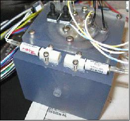
This propulsion system, like the one Aerospace flew on MEPSI in 2006, is fabricated out of plastic using additive manufacturing. The propellant tank and feed lines are voids in a single block of plastic. MEPSI had a plastic converging/diverging nozzle integrated into the structure, but for this project, the team used an aluminum nozzle with a 700 µm diameter machined throat. Figure 16 shows a photograph of an early prototype for thrust testing. The nozzle mounts in the protrusion near the bottom center, and the valves have been upgraded in number (to allow parallel paths for improved reliability) and in flow capacity.
Optical Ground Station
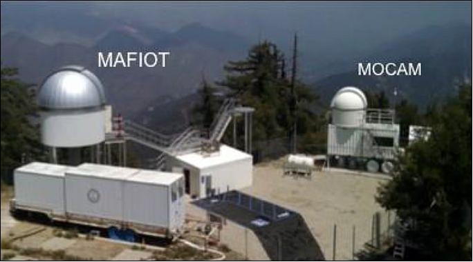
In addition to spacecraft systems, successful optical communication requires a compatible optical ground receiving station. Two ground terminals operated by The Aerospace Corporation are located at Mt. Wilson, California, at an altitude of 1750 m. The MOCAM (Mobile Communications and Atmospheric Measurements ) station was completed in 2013 and supports a COTS (Commercial Off-the-Shelf ) 30 cm diameter Cassegrain telescope. Initial experiments will be conducted with this system. Future experiments will take advantage of a newer facility, MAFIOT (Mt. Wilson Aerospace Facility for Integrated Optical Tests), which is nearing completion and operates a Ritchey‐Chrétien telescope of 80 cm diameter. Figure 28 shows the two optical ground stations at Mt. Wilson. Figure 29 shows a schematic drawing of the relevant MOCAM ground station elements.
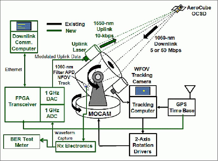
Rough satellite tracking will use high‐accuracy ephemerides generated from spacecraft GPS fixes on previous orbits, and a WFOV (Wide Field of View) tracking camera will provide closed loop feedback to keep the downlink laser photons centered on the detector. This system has been used to track other LEO spacecraft and is fully capable of receiving our optical downlink. The easiest test mode is to download known data patterns and read the BER from the test meter. As the project gains experience, spacecraft imagery and videos will downloaded.
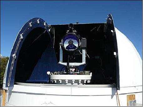
Figure 30 shows a photograph of a Meade 30 cm diameter telescope mounted on a high-precision gimbal system that allows tracking of LEO spacecraft.
The optical ground station receive telescope will have an APD (Avalanche Photodiode) detector at its focus, and an avalanche quad photocell to provide off-angle error signals for closed-loop satellite tracking. Rough satellite tracking will use high-accuracy ephemerides generated from spacecraft GPS fixes on previous orbits, and a WFOV (Wide Field of View) tracking camera will provide closed loop feedback to keep the downlink laser photons centered on the APD. This system has been used to track other LEO spacecraft and is fully capable of receiving the OCSD optical downlink. The easiest test mode is to download known data patterns and read the BER from the test meter. As experience is gained, the project team will download spacecraft imagery and videos, and use the FPGA transceiver to process these data.
The uplink laser beacon on the ground station provides the signal for closed-loop tracking of the ground station by the satellite. The 10 W, 1550 nm, uplink laser is eye safe within 50 m of the telescope, and meets FAA (Federal Aviation Administration) requirements for operation without an aircraft spotter. The project will test this laser uplink mode first, followed by the mechanically‐simpler open-loop tracking mode based on star tracker data. Long term, open-loop tracking could reduce ground station complexity and cost.
The ground station network of Aerospace currently consists of three Internet-connected RF ground stations located in El Segundo, California, College Station, Texas, and Gainsville, Florida.
The top three tracking modes in Table 2 rely on spacecraft attitude and inertial sensors to provide open-loop attitude knowledge for pointing the downlink beam at the ground station. The last mode relies on open-loop attitude knowledge to roughly point at the ground station, and then use a position-sensitive (the quad photodiode) beacon detector to lock onto the uplink to provide closed-loop pointing. Pointing accuracy is estimated at ~0.2º, based on experience with quad cell sun sensors and the reaction wheels.
Optical Link Budget
The optical downlink link budget is given in Table 3 for both ground station apertures for the 6 W laser transmitter on the Pathfinder spacecraft. Link parameters are 900 km range, 1064 nm wavelength, 0.30º FWHM angular beam spread, an angular pointing error of 0.15º, 80% atmospheric transmission, 32% scintillation loss, 50% telescope collection efficiency, and a detector NEP (Noise Equivalent Power) of 5 x 10-14 W/√Hz. MOCAM enables data rates up to 40 Mbit/s and MAFIOT enables rates up to 300 Mbit/s at this range.
Parameter | MOCAM | MAFIOT |
Data rate | 40 Mbit/s | 300 Mbit/s |
Photons/pulse onto detector | 300 | 290 |
Average power on detector | 2.3 nW | 1.6 nW |
SNR (Signal/Noise Ratio) | 10 dB | 14 dB |
Proximity Operations and Sensor Complement
Note: The proximity operations are only used in the follow-up mission of two 1.5U CubeSats.
While the optical communications demonstrations can be performed independently on each spacecraft, the remaining payload demonstrations require proximity operations between the two spacecraft. A secondary goal of the OCSD program is to demonstrate proximity operations, and the tertiary goal is to demonstrate on-orbit propulsion.
After attaining orbital altitude, the two 1.5U CubeSats will be deployed from the same P-POD. After a month of on-orbit checkout, both spacecraft will be brought within 2 km of each other, using variable drag for cooperative orbit rephasing, and cold gas thrusters for cross-track maneuvering. Each satellite has deployed wings that allow varying the ballistic coefficient by up to a factor of 5 by changing spacecraft orientation.
With the +Z or –Z spacecraft directions pointing in the flight direction, the projected spacecraft area is about 100 cm2. With the wings perpendicular to the flight direction, the projected spacecraft area is maximized at about 500 cm2. Unfortunately, drag in the low-drag configuration is very sensitive to pointing errors; a 10º pitch offset increases the projected area to 185 cm2. The medium-drag mode has the wings parallel to the flight direction and the +Z axis zenith pointing. The projected spacecraft area in this orientation is about 150 cm2. This mode is insensitive to small angle error about all three axes. In addition, it ensures that at least one star tracker will see stars. These high- and medium-drag modes provide a repeatable drag ratio of 3.3 to 1.
Figure 31 shows the calculated time, in days, for the chase spacecraft to match the target spacecraft altitude using 4:1 variable drag with our spacecraft, as a function of target spacecraft altitude. Naturally, the chase spacecraft has to be higher than the target one. These calculations are for nearly circular orbits and include in-track corrections of up to several hundred km. The expected orbit for OCSD is elliptical with a ~400 km perigee and a ~700 km apogee, and in this case, doubling the 400 km altitude values provides a good estimate of maneuver time. Rendezvous maneuver times in excess of a month are excessive for a total 6 month on-orbit operation, and propulsion may be required to expedite the maneuver. In LEO, a 1 m/s delta-V enables an orbit altitude change of about 2 km, and an additional 2 m/s delta-V are budgeted to handle the cross-track errors that are significantly harder to correct using just differential drag.
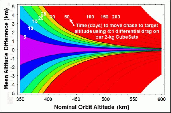
Figure 32 shows the overall proximity operations concept. Differential drag and a small amount of propulsion are used to bring the chase spacecraft 2 km ahead, or behind, the target spacecraft. This staging point allows further testing of the propulsion system, initial testing of the laser rangefinder, and gaining experience with setting up Hill's orbits about a virtual spacecraft. When viewed in the co-rotating frame of the staging point, the team will exercise its ability to place the chase in a co-orbit about the staging point with different mean radii and eccentricities. After this stage, the chase CubeSat will be moved to a starting point of 1 km from the target spacecraft in a 200 m radius Hill's orbit about this point. A 1 cm/s in-track impulse will then put the chase CubeSat in a helical trajectory that corkscrews about the target orbit and slowly translates towards, and later beyond, the target. Another 1 cm/s impulse in the opposite direction, 1 km past the target, halts the translational motion. This sequence can be reversed and repeated over 300 times without using up all of the propellant.
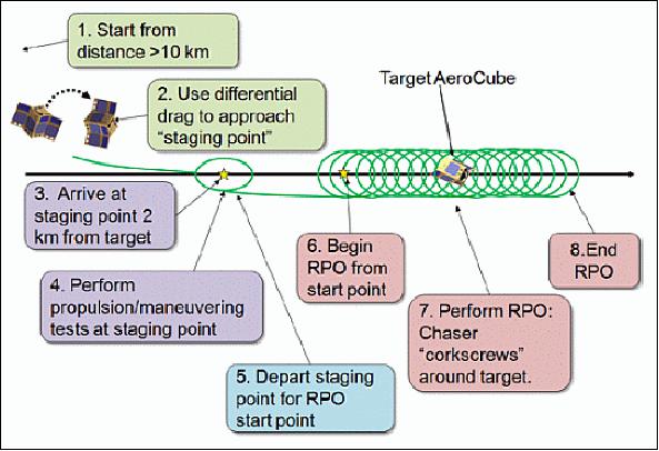
The RPOs (Relative Proximity Operations) enable the team to approach a 200 m minimum range while minimizing the possibility of collision. A one-way corkscrew trajectory takes 22 hours, thus allowing the team to monitor progress and abort if necessary. The project plans on having four geographically-separated RF ground stations (Florida, Texas, California, and Hawaii) to provide eight or more satellite contact opportunities during an RPO. Having high-accuracy orbital ephemerides significantly reduces the possibility of collision for the trajectory.
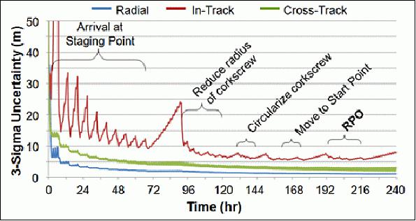
Figure 33 shows the calculated chase spacecraft 3σ position uncertainties for radial, in-track, and cross-track errors for the week-long setup phase and RPO stage. Fortunately, multiple RPOs can be accomplished in sequence without returning to the setup phase. Note that the errors are sequentially reduced as more GPS data are incorporated, resulting in improved estimates of the actual spacecraft drag. This requires flying in a fixed drag orientation over eight or more days.
References
1) Siegfried W. Janson, Richard P. Welle, "The NASA Optical Communication and Sensor Demonstration Program," Proceedings of the 27th AIAA/USU Conference, Small Satellite Constellations, Logan, Utah, USA, Aug. 10-15, 2013, paper: SSC13-II-1, URL: http://digitalcommons.usu.edu/cgi/viewcontent.cgi?article=2918&context=smallsat
2) Siegfried W. Janson, Richard P. Welle, "The NASA Optical Communication and Sensor Demonstration Program; An Update," Proceedings of the AIAA/USU Conference on Small Satellites, Logan, Utah, USA, August 2-7, 2014, paper: SSC14-VI-1, URL: http://digitalcommons.usu.edu/smallsat/2014/NextPad/1
3) Siegfried W. Janson, Richard P. Welle, Todd S. Rose, Darren W. Rowen, David A. Hinkley, Brian S. Hardy, Steph-an D. La Lumondiere, Geoffrey A. Maul, Nicolette I Werner, "The NASA Optical Communication and Sensors Demonstration Program: Preflight Up-date," Proceedings of the 29th Annual AIAA/USU Conference on Small Satellites, Logan, Utah, USA, August 8-13, 2015, paper: SSC15-III-1, URL: http://digitalcommons.usu.edu/cgi/viewcontent.cgi?article=3178&context=smallsat
4) Richard P. Welle, Siegfried Janson, Darren Rowen, Todd Rose, "CubeSat‐Scale Laser Communications," 31st Space Symposium, Technical Track, Colorado Springs, CO, USA, April 13-14, 2015, URL: http://www.spacesymposium.org/sites/default/files/
downloads/R.Welle_31st_Space_Symposium_Tech_Track_paper.pdf
5) "United Launch Alliance Successfully Launches Payload for the National Reconnaissance Office - Atlas V Rocket also Delivers 13 CubeSats to Orbit," ULA, Oct. 8, 2015, URL: http://www.ulalaunch.com/ula-successfully-launches-NROL55.aspx
6) Montgomery Kirk, David Callen, George Budris, "The Atlas V Aft Bulkhead Carrier Update – Past Missions, Upcoming Launches and Future Improvements," Proceedings of the 29th Annual AIAA/USU Conference on Small Satellites, Logan, Utah, USA, August 8-13, 2015, paper: SSC15-II-3, URL: http://digitalcommons.usu.edu/cgi/viewcontent.cgi?article=3172&context=smallsat
7) Brian Webb, "Vandenberg AFB Launch Schedule," Sept. 13, 2015, URL: http://www.spacearchive.info/vafbsked.htm
8) Richard P. Welle, Christopher M. Coffman, Dee W. Pack, and John R. Santiago, "CubeSat Laser Communication Crosslink Pointing Demonstration," Proceedings of the 33rd Annual AIAA/USU Conference on Small Satellites, August 3-8, 2019, Logan, UT, USA, paper: SSC19-III-08, URL: https://digitalcommons.usu.edu/cgi/viewcontent.cgi?article=4402&context=smallsat
9) T. S. Rose, D. W. Rowen, S. LaLumondiere, N. I. Werner, R. Linares, A. Faler, J. Wicker, C. M. Coffman, G. A. Maul, D. H. Chien, A. Utter, R. P. Welle, and S.W. Janson,"Optical Communications Downlink from a 1.5U CubeSat: OCSD Program,"Proceedings of the 32nd Annual AIAA/USU Conference on Small Satellites, Logan UT, USA, Aug. 4-9, 2018, paper: URL: https://digitalcommons.usu.edu/cgi/viewcontent.cgi?article=4298&context=smallsat
10) Dee W. Pack, David R. Ardila, Eric Herman, Darren W. Rowen, Richard P. Welle, Sloane J. Wiktorowicz, and Bonnie W. Hattersley, "Two Aerospace Corporation CubeSat Remote Sensing Imagers: CUMULOS and R3," Proceedings of the 31st Annual AIAA/USU Conference on Small Satellites, Logan UT, USA, Aug. 5-10, 2017, paper: URL: https://digitalcommons.usu.edu/cgi/viewcontent.cgi?article=3613&context=smallsat
11) Richard E. Hodges, Dorothy K. Lewis, Matthew J. Radway, Armen S. Toorian, Fernando H. Aguirre, Daniel J. Hoppe, Biren N. Shah, Andrew A. Gray, "The ISARA Mission – Flight Demonstration of a High Gain Ka-Band Antenna for 100Mbps Telecom," Proceedings of the 32nd Annual AIAA/USU Conference on Small Satellites, Logan UT, USA, Aug. 4-9, 2018, paper: SSC18-VI-03, URL: https://digitalcommons.usu.edu/cgi/viewcontent.cgi?article=4104&context=smallsat
12) Dee W. Pack, Christopher M. Coffman, and John R. Santiago, "A Year in Space for the CUbesat MULtispectral Observing System: CUMULOS," Proceedings of the 33rd Annual AIAA/USU Conference on Small Satellites, August 3-8, 2019, Logan, UT, USA, paper: SSC19-XI-01, URL: https://digitalcommons.usu.edu/cgi/viewcontent.cgi?article=4447&context=smallsat
13) Darren Rowen, Siegfried Janson, Chris Coffman, Richard Welle, David Hinkley, Brian Hardy, and Joseph Gangestad, "The NASA Optical Communications and Sensor Demonstration Program: Proximity Operations," Proceedings of the 32nd Annual AIAA/USU Conference on Small Satellites, Logan UT, USA, Aug. 4-9, 2018, paper: SSC18-I-05, URL: https://digitalcommons.usu.edu/cgi/viewcontent.cgi?article=4066&context=smallsat
14) Siegfried Janson, Richard Welle, Todd Rose, Darren Rowen, Brian Hardy, Richard Dolphus, Patrick Doyle, Addison Faler, David Chien, Andrew Chin, Geoffrey Maul, Chris Coffman, Stephen D. La Lumondiere, Nicolette I Werner, David Hinkley, "The NASA Optical Communications and Sensor Demonstration Program: Initial Flight Results," Proceedings of the 30th Annual AIAA/USU SmallSat Conference, Logan UT, USA, August 6-11, 2016, paper: SSC16-III-03, URL: http://digitalcommons.usu.edu/cgi/viewcont
ent.cgi?article=3346&context=smallsat
15) Joshua Buck, "CubeSat to Demonstrate Miniature Laser Communications in Orbit," NASA, Oct. 9, 2015, URL: http://www.nasa.gov/press-release/cubesat-to-
demonstrate-miniature-laser-communications-in-orbit
16) "Nusil CV-2946 data sheet," Nusil technology LLC, Carpenteria, CA, USA, May 2014, URL: http://nusil.com/products/ProductProfiles/CV-2946/CV-2946P.pdf
17) "DLEM SR 1.55 µm Diode-Laser Rangefinder," Jenoptik Defense & Civil Systems, URL: http://www.jenoptik.com/en-diode-laser-rangefinder-dlem-sr
18) "WARP speed ahead!," SSTL, URL: https://web.archive.org/web/20130212075231/http://www.sstl.co.uk/Blog/January-2013/WARP-speed-ahead
The information compiled and edited in this article was provided by Herbert J. Kramer from his documentation of: "Observation of the Earth and Its Environment: Survey of Missions and Sensors" (Springer Verlag) as well as many other sources after the publication of the 4th edition in 2002. - Comments and corrections to this article are always welcome for further updates (eoportal@symbios.space).
Spacecraft Launch Mission Status Sensor Complement Optical Ground Station References Back to top