AeroCubes OCSD-B and -C
Non-EO
NASA
Communications
Quick facts
Overview
| Mission type | Non-EO |
| Agency | NASA |
| Launch date | 12 Nov 2017 |
| End of life date | 12 Nov 2019 |
AeroCubes OCSD-B and -C (Optical Communication and Sensor Demonstration)
Spacecraft Launch Mission Status References
Background: A common challenge in developing small-satellite-borne EO (Earth Observation) missions is getting the data to the ground. For many next-generation EO missions, such as hyperspectral imaging or SAR missions, the volume of data generated is large enough to tax most conventional RF (Radio Frequency) downlink systems. For other EO missions, such as hazard monitoring or data collection for weather forecasting, data latency is a key issue. It is well known that laser downlinks offer the potential of multi-Gbit/s download speeds, which are typically two to three orders of magnitude faster than RF downlink speeds. On the other hand, optical downlink systems can easily be interrupted at any given ground station (possibly for long periods) due to cloud cover. 1)
The EDRS (European Data Relay System) is being developed to address both the data-latency issue and the cloud-cover issue by placing a set of data relay satellites in GEO (Geosynchronous Earth Orbit). These satellites receive optical communication from EO satellites in LEO (Low Earth Orbit) and relay those communications to the ground using a Ka-band RF downlink. Because of the range from LEO to GEO, however, this system requires that LEO satellites carry a large (~35 kg) laser terminal.
An alternative approach to the problem is to develop a network of small optical relay satellites in LEO that allow for short range optical or RF communication from EO satellites to the network. The LEO network satellites then relay the data around the Earth to a network satellite in view of an optical ground station not obscured by clouds. This approach allows for high data rates and low latency, and can be implemented, in principle, with a much smaller optical terminal on the EO satellite.
Implementing such a system requires the development of both optical downlinks and optical crosslinks for a small, preferably CubeSat-scale, satellite. The first optical downlink developed for a CubeSat is the NASA OCSD (Optical Communication and Sensor Demonstration) program. These satellites, developed by The Aerospace Corporation and currently scheduled for launch in late 2017, have been designed for optical downlink rates up to 200 Mbit/s. Follow-on optical downlink demonstrators are being developed by Aerospace for rates approaching 1 Gbit/s. In addition, we have developed concepts for CubeSat-based optical crosslink nodes that would support the eventual deployment of a LEO network of optical relay satellites to enable high-volume, low-latency downlink from new Earth-observation satellites. The availability of such a system would also enable new capabilities for small EO spacecraft with limited mass and power budgets for downlink, further supporting next-generation distributed EO satellite sensing systems.
Recent progress in sensor technology has allowed LEO satellites to shrink significantly in size, disrupting a legacy industry where traditional satellites cost $500 million to $1 billion to build and launch. Major investments are being made to address the new opportunities this provides for data collection, and many companies are launching nanosatellites and/or microsatellites into LEO to capture this opportunity. The rapidly expanding satellite infrastructure is generating vast amounts of data, with no signs that the trend will level off. To bring all that data down from LEO requires an average communication rate of several Gbit/s, continuously, and that demand will continue to grow.
Typically, most satellites download data via space-to-ground RF links, communicating directly with fixed ground stations as the satellites fly within range. The current ground station infrastructure has several key limitations that present significant challenges as the satellite industry continues to grow. Satellite-to-ground communications are "line-of-sight," meaning that ground stations are able to receive data directly only from satellites that are above the local horizon. The duration of a satellite pass over a ground station depends on the altitude of the satellite and the distance between the ground station and the ground track of the satellite. With satellites in LEO, the maximum pass duration is typically less than ten minutes.
The frequency of passes is strongly dependent on the satellite orbit parameters and the location of the ground station. For example, a satellite in equatorial orbit will pass over an equatorial ground station on each orbit. With a typical orbital period of 90 minutes, that means 16 passes per day. Similarly, a satellite in a polar orbit will pass over a ground station located at the North Pole once per orbit. On the other hand, the satellite in polar orbit will pass over the equatorial ground station between two and four times per day depending on the alignment of the ground track with the location of the ground station. However, the satellite in equatorial orbit will never pass over the polar ground station. Most LEO satellites are in orbits at some inclination between equatorial and polar, and most ground stations are located at latitudes well south of the North Pole. As such, the pass frequency for any given satellite over any given ground location will typically be three to five times per day for ground stations that are not at high latitude (above about 60 degrees) and not at latitudes higher than the orbital inclination of the satellite.
The consequence of limitations on pass duration and frequency is that a satellite will be within communication range of a given ground station for no more than 10% of a day, and typically for less than 2% of a day. These constraints on pass duration and pass frequency are driven by orbital dynamics and can be overcome only by increasing the number of ground stations or locating the ground stations at very high latitudes. Avoiding downlink constraints requires a large number of geographically diverse ground stations that are inherently underutilized.
One method of compensating for the limitations on ground contact time is to increase the data transmission rate during what contact time is available. High data rates in the RF require some combination of high transmitter power and high-gain antennas on the satellite and the ground station. High power transmitters and high-gain antennas on the space segment are constrained by power and mass limitations on the satellite. High-gain antennas on the ground are not mass limited, but tend to be very large (10 meters or more in diameter) and require significant capital investment.
Significant further increases in downlink capability can be obtained by developing an in-space relay network configured to allow continuous communications from space to ground, as illustrated in Figure 1. With such a network in place, an EO satellite in LEO with data to download could simply transfer that data to a nearby node in the network. From there it would be forwarded through crosslinks to a network node within view of an available ground station. Such a network could allow high-volume, low-latency download from anywhere in LEO.
For new satellite companies leveraging advances in satellite capabilities, capital investment for an extended ground station network is particularly burdensome because the size and cost of the ground network does not scale with the size of the satellites. Ground station costs have not scaled at the same rate as satellite costs, requiring significant further investment to match growth in satellite capacity. An available LEO network could minimize, or even eliminate, the need for new satellite companies to develop their own ground network.
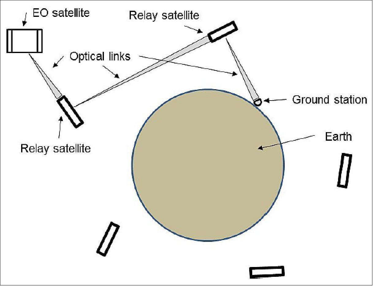
Optical Communications
The key challenge in implementing a high-rate optical communication system is the pointing and tracking of the laser beam. Laser communication achieves high data rates with moderate powers by focusing the transmitted power into a narrow beam, which must be directed with sufficient accuracy and precision to ensure that the intended receiver is reasonably centered in the beam profile.
The importance of pointing is illustrated in Figure 2, which shows the data rate achievable as a function of transmit pointing accuracy for three different ranges. Besides pointing accuracy, the other factors that affect data rate are transmit power, the size and efficiency of the collection optics and receiver, and, of course, the range to the target. Ultimately, the goal is to get as many photons as possible into the collector, and to convert those photons to data bits. For a given laser power and a given detector system, the key factors are the beam divergence (which must be wide enough to compensate for uncertainty in pointing) and the range to the target. The data rate is approximately proportional to the optical power falling on the collector. As such, the data rate will be inversely proportional to the square of the beam divergence (which is limited by the pointing accuracy), and also inversely proportional to the square of the distance to the target.
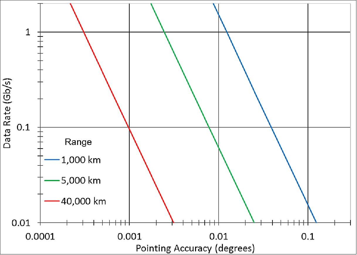
The three cases illustrated in Figure 2 cover three different ranges and assume a constant laser power, constant collector area, and constant detector efficiency. The shortest range, 1,000 km, is typical of LEO-to-ground links. The intermediate range, 5,000 km, is approximately the longest range possible with a crosslink in LEO. The longest range shown, 40,000 km, is typical of a link from LEO to GEO. In this simplified illustration, the effect of atmospheric distortions on the downlink have been neglected. To compensate for this, the undistorted optical power directed at the terrestrial receiver would have to be increased, perhaps by as much as an order of magnitude. This will shift the blue trace to the left, but not beyond the green trace. Furthermore, for ground-based receivers, there is the option of using larger collection optics than may be practical on spaceborne receivers. There are also options for active compensation for atmospheric distortions. As such, a LEO transmitter with sufficient pointing capacity for a 5000 km crosslink should have adequate pointing capacity for a 1000 km downlink at the same data rate.
Constellations
Even though optical communication systems are capable of very high data rates, they are limited by the availability of optical ground stations, and by the inability of optical communication signals to penetrate clouds, which further limits the utility of existing optical ground stations. Looking to the future, these problems can be addressed by using orbital optical relay systems to move data from the point where it is generated to a location where there is clear access to a ground station. Ultimately, it will be possible to establish an all-optical backbone in space that would allow EO satellites to download data not by transmitting it directly to the ground, but by transmitting it to a node in the optical network, as illustrated in Figure 1. A single constellation would be able to provide downlink services for a number of client satellites, or even provide a means of moving data optically from point to point on the ground. With a sufficient number of nodes in the network, it will reach a point where there is always a node within range of any given LEO satellite, as well as at least one node within range of an available ground station. This will enable download of data generated in LEO in essentially real time, with little to no latency beyond that driven by the speed of light.
The number of nodes that would be required in such a constellation to ensure that one is always visible to a client satellite depends on the altitude at which the constellation is flying. At one extreme, the EDRS (European Data Relay System) places optical relay satellites in GEO. In GEO, only three relay satellites are required to cover the entire globe, as well as all of LEO. On the other hand, by placing the relay satellites in GEO, any client satellites in LEO have to satisfy the pointing requirements for a 40,000 km link, which can be very challenging, as illustrated in Figure 2.
Spacecraft
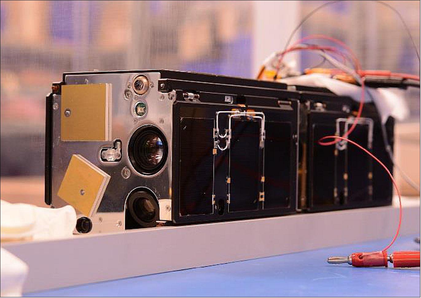
NASA is sponsoring an Aerospace-built CubeSat, AeroCube-7, as part of its OCSD (Optical Communication and Sensor Demonstration) program. AeroCube-7 is designed to demonstrate two significant capabilities that will be of value for the expanding small satellite industry: demonstrating high-speed optical transmission of data and proximity operations between two small satellites. 6)
The OCSD program was initiated in 2012 by NASA’s Small Spacecraft Technology Program (SSTP) to demonstrate optical communications from low Earth orbit to small ground terminals, proximity operations using CubeSats, and a CubeSat-compatible thruster. A risk-reduction “Pathfinder” spacecraft (AeroCube OCSD-A) was launched in October, 2015, followed by the main flight units (AeroCubes OCSD-B and -C) in November of 2017. 7)
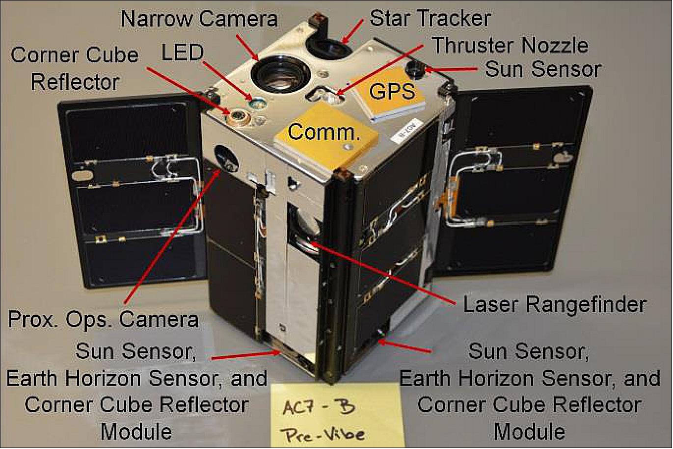
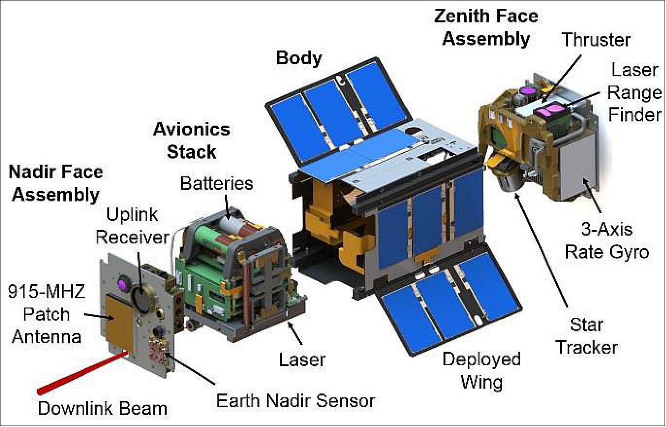
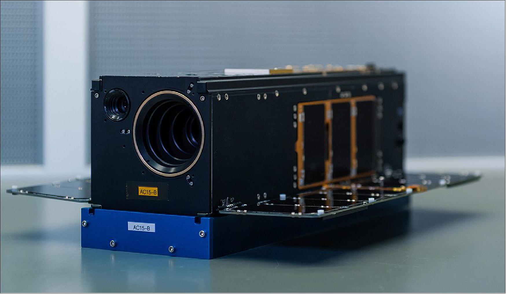
AeroCube-OCSD-B is a 1.5U CubeSat with a 2 W output downlink laser at 1064 nm wavelength with a 0.05º FWHM (Full Width Half Maximum) angular beamwidth, an uplink laser-receiver/quadcell, two independent 915 MHz communications transceivers, a GPS receiver, a 3-axis attitude control system designed for better than 0.15º pointing accuracy, a laser rangefinder, a corner cube reflector on each face, a 10 Mpixel color camera with180º FOV (Field of View), a 10 Mpixel proximity operations color camera, a 10 Mpixel color camera with a 14º FOV for Earth observation, two deployable solar panels, three blue LED (Light-Emitting Diode) beacons, and a distributed computing system composed of over 20 microprocessors and 3 field-programmable gate arrays (FPGAs). An 8 GB flash RAM memory card is used for data storage. The attitude control system has six two-axis sun sensors, four Earth horizon sensors, an Earth nadir sensor, two sets of three-axis magnetometers, two three-axis rate gyros, three magnetic torque rods, three reaction wheels, and two star trackers.
AeroCube-OCSD-C is a copy of the -B spacecraft, but with a wider 0.15º FWHM angular beamwidth for the downlink laser. Both spacecraft have a mass of 2.31 kg.
Steam Thruster Selection and Issues
A steam thruster was chosen by the Principal Investigator in 2013 after interactions with NASA safety engineers during the preliminary design review. There were no toxicity, flammability, or carcinogenic issues, no explosion hazards, and the system did not require a pressure vessel for propellant storage. It therefore met the CubeSat specifications without requiring a waiver. In addition, water has a low molecular weight, and the calculated specific impulse of 90 s for a 10:1 expansion from a 40º C plenum was much higher than that for butane or any Freon.
A challenging feature of the steam thruster is that it’s an evaporating liquid thruster that requires a heat input of 2.9 W/mN to support continuous thrust. This is the heating rate required to vaporize water at the required mass flow rate needed to generate a given thrust level. In addition, according to one-dimensional isentropic expansion calculations, the propellant tank has to maintain a 45ºC minimum temperature to prevent vapor freezing before it reaches the 700 µm diameter nozzle throat. Liquid entrainment and freezing have been major issues in thruster design, testing, and on-orbit operation.
The first known on-orbit steam thruster test occurred in February, 2004 on the UK-DMC microsatellite. The spacecraft and thruster were designed and built by SSTL (Surrey Satellite Technology Ltd.) in the United Kingdom. A 10 cm long, 8 mm internal diameter tubular propellant tank was filled with 2.06 grams of water and heated to 200ºC. Ground testing revealed a number of issues such as ice plug formation and rapid ejection of propellant mass, but the limited schedule allowed only one modification: using a sonic orifice instead of a converging/diverging nozzle to prevent ice buildup in the nozzle expansion region. The first on-orbit thruster test generated 3.3 mN of thrust over 10 cycles using a 0.1 s “on” / 0.9 s “off” duty cycle, and the nozzle temperature dropped by 25ºC. The calculated thrust level for gas-only ejection was 0.2 mN. Liquid water was flowing through the thruster nozzle, yielding a specific impulse of only 5 s, compared to an expected 50 s using a sonic orifice nozzle. The second test, 10 days later, produced no thrust.
SSTL flew a butane thruster on the SNAP-1 nanosatellite with a similar on-orbit problem with expelling some liquid with gas, at least for initial thrusting. As a result, thrust levels for the first 20 seconds of operation were higher than normal, and the total mission ΔV was reduced to 60% of expected.
The last steam thruster put into orbit was a water/alcohol resistojet on the University of Surrey Space Center Surrey Training, Research, and Nanosatellite Demonstrator (STRaND-1) CubeSat on February 25, 2013. Downlink was lost a little more than a month later, on March 30, 2013, and no resistojet flight performance data have been reported.
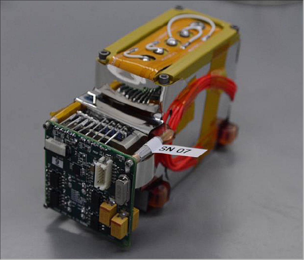
Figure 6 is a photograph of the OCSD steam thruster. The structure is fabricated in plastic using additive manufacturing, but the nozzle is machined in aluminum to provide smooth surfaces at the 20 µm size scale. Engineering challenges that we overcame included sensor and feed-through corrosion by water, thermal control and insulation, and ice plugs that formed during the first few firings in vacuum.
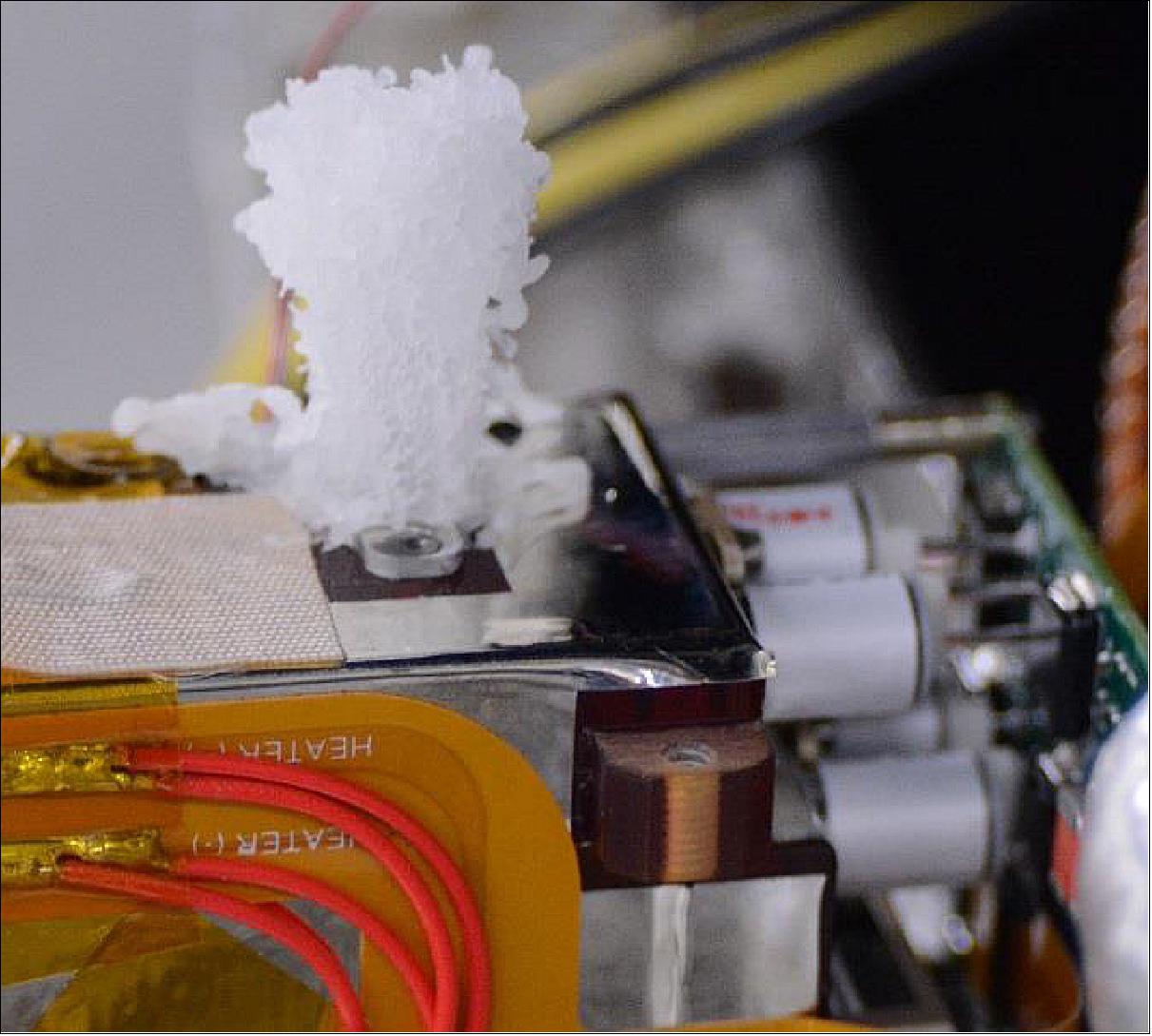
Ground tests of the steam thruster: Figure 7 is a photograph of a ~2-cm high ice plug that formed above the nozzle exit during a ground test. Ice plugs typically form during the first few test firings in vacuum when liquid water is ejected into vacuum. The project filled the propellant tanks at ambient pressure using a water-filled syringe. When sealed, the internal plenum pressure is 1 atmosphere; much higher than the 0.07 - 0.11 bar pressure range for water vapor between 40º and 48º C. To limit ejection of liquid water, we limited filled water volume to 26 cm3. This increased the ullage (headspace) fraction. In addition, thrusters were briefly test fired in a vacuum to vent excess air pressure before further environmental testing and integration of these thrusters into flight spacecraft.
All flight thrusters were thermally-cycled from +61º to -24ºC for 20+ cycles, and their mass and internal pressure were monitored after each test to uncover leaks. A thermal bake out test of 6 hours under vacuum at pressures below 10-4 Torr at 60ºC yielded a post-test mass loss of only 0.02 grams for one unit, and 0.06 grams for the second unit. These minor mass losses were attributed to outgassing and not propellant loss. Both units were subjected to vibration testing at GEVS (General Environmental Vibration Specification) 14.1 g rms levels for one minute at each axis, with no issues.
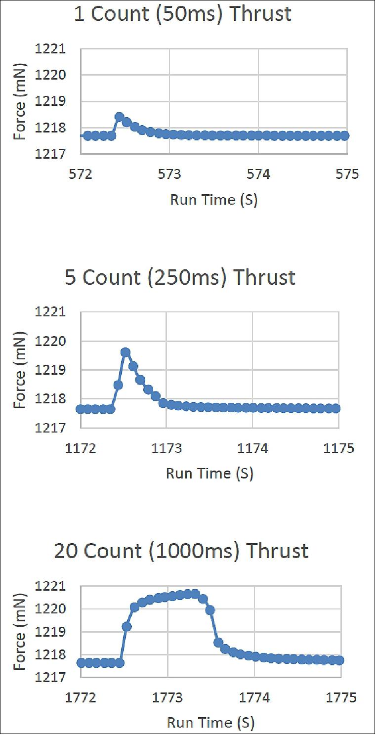
The Figure 8 plots measured thrust levels in vacuum produced by serial number 08 steam thruster module, operating with a body and exit nozzle temperature of 40ºC, and valve open times of 50, 250, and 1000 milliseconds, respectively. The thruster was put on a digital weight scale, with the nozzle pointing up, in a vacuum chamber. Measured force is the weight of the module, plus any offset, plus thrust. Thrust is determined by subtracting the baseline from the instantaneous force measurement. The impulse bit for the 50 and 250 millisecond valve opening times are 0.2 and 0.6 mNs, respectively. At 1000 milliseconds, the impulse bit increases to 2.8 mNs. For open times greater than 1.5 seconds, the impulse bit scales as 3.0 mN times the valve open time.
Launch
Launch: Two innovative 1.5U CubeSats (AeroCubes OCSD -B and -C) designed and built by The Aerospace Corporation were successfully launched on Nov. 12, 2017 from NASA's Wallops Flight Facility in VA aboard Orbital ATK's Cygnus spacecraft (CRS OA-8 mission). 8) The spacecraft will deliver vital supplies and scientific equipment to the space station as part of Orbital ATK’s CRS (Commercial Resupply Services) contract with NASA. 9)
Orbit of ISS: Near-circular orbit, altitude of ~ 400 km, inclination = 51.6º, period = 92.6 minutes.
For the OA-8 mission, Orbital ATK is using the Enhanced Cygnus PCM (Pressurized Cargo Module) to deliver cargo to the space station. The cargo capability of the Enhanced Cygnus, developed by Thales Alenia Space, is more than 3500 kg with a total volumetric capacity of 27 m3 (the ascent cargo mass is 3,350 kg).
Cygnus carried the following CubeSats:
• ISARA (Integrated Solar Array and Reflectarray Antenna), a NASA/JPL 3U CubeSat demonstration mission of a Ka-band reflect array antenna.
• EcAMSat (E. coli AntiMicrobial Satellite), a 6U CubeSat of NASA/ARC to investigate space microgravity effects on the antibiotic resistance of E. coli.
• Lemur-2 x 8, a 3U CubeSat of Spire Global (global ship tracking).
• CHEFsat (Cost-effective High E-Frequency Satellite), a 3U CubeSat of NRL (Naval Research Laboratory) to test COTS technologies.
• Asgardia-1, a 2U CubeSat of Asgardia Space to demonstrate long-term data storage in orbit. After leaving the ISS, the robotic Cygnus will boost itself into a 500 km orbit and deploy Asgardia-1.
• OSCD x 2 (Optical Communication and Sensor Demonstration), two 1.5U CubeSats of The Aerospace Corporation to study high-speed optical transmission of data and small spacecraft proximity operations.
• PropCube-2 (Fauna), a 1U CubeSat of NPS (Naval Postgraduate School) for ionospheric calibration measurements.
• TechEdSat-6, a 3U CubeSat, developed by students of SJSU (San Jose State University), the University of Idaho, and NASA/ARC (Ames Research Center). TechEdSat 6 is the latest in a series of CubeSats testing an “exo-brake” deorbit system, a drag device that uses aerodynamic forces — and not propulsion — to re-enter the atmosphere. The technology could eventually allow some space station research samples to return to Earth sooner, and at less expense.
Mission Status
• June 17, 2020: The COVID-19 pandemic and the ensuing wide-scale safer-at-home order responses have made it abundantly clear that a return to "business as usual" may never happen. This "new normal" will require new, innovative methods of providing services that can be implemented quickly, dynamically, and often remotely. 10)
- In spite of the challenges presented by COVID-19 and social distancing mandates, The Aerospace Corporation has adjusted seamlessly across the enterprise in adapting to current conditions. A prime example can be found in Aerospace’s AeroCube SmallSat operations team, which is continuing to provide unabated spacecraft commissioning despite having a significantly reduced on-site workforce. In addition, other aspects of the AeroCube program are being quickly reconfigured to enable a teleworking team to provide the same services that have up until recently been provided by local staff.
- More importantly, this new standard may lead to improved operational methods that augment how Aerospace operates going forward.
New Approaches to Standard Practices
- Downlink communication lasers are critical to AeroCube functionality, and have typically required the establishment of an alignment of the laser boresight and a star tracker system. Until recently, this was accomplished by having the AeroCube generate a spiral scan pattern detectable to the optical ground telescope located in Aerospace’s El Segundo campus, and having on-site personnel process data to establish alignment. Given the impact that the pandemic has had upon Aerospace operations, this approach was not currently feasible under mandatory telework conditions. However, necessity being the mother of all invention, it has prompted the team to develop new approaches to accomplishing the same goal.
- “The optical ground station in the E-pod dome in El Segundo typically required a 2-person crew working in close proximity,” said Darren Rowen, Director of Aerospace’s Small Satellite Department. “With the COVID-19 operating restrictions, the team thought creatively and was able to develop a method using the partner spacecraft’s star tracker as a receiver instead of the ground telescope. This required software updates for both space and ground systems to support this new method, and the team’s experience with on-orbit reprogramming proved invaluable in enabling this modified approach.”
- The technology in question is up to the challenge, as the sensor in the star tracker has extended sensitivity into the near-infrared and can readily detect a 1064 nanometer (nm) laser signal. Furthermore, recently developed camera software can provide video of down-sampled and compressed frames small enough to downlink via ultra-high frequency (UHF) radio, enabling synchronization with the spiral scan. Most significantly, this new communication laser alignment method effectively reduces the on-site staffing requirement to zero.
- “The traditional laser alignment process is time-consuming to execute with ground telescopes due to limited opportunities imposed by orbital geometry and weather. The new cross-vehicle alignment methodology can now be executed multiple times for refinement and validation in a matter of days,” Rowen added. Given that support from the ground telescope team is no longer required, this new approach is expected to be a preferred methodology for future missions when it is available. And if any further proof of the viability of remote work was needed, the necessary software updates that made this possible were developed by remote personnel, and the spacecraft software was also updated on-orbit by remote operators.
Pandemic Realities Prompt New, Improved Methodologies
- Going forward, new short-wave infrared band sensors will yield data on cloud backgrounds to inform future low Earth orbit missions, and a recent development mission will provide a lessons-learned baseline for rapid, commercial off the shelf-based spacecraft and payload production. Most importantly, this new, agile methodology may obviate the need for personnel operating within close proximity to ground stations, potentially ushering in a new era of decentralized, remote operations.
- Aerospace’s new approach to the AeroCube laser alignment process is testimony to its continued dedication to innovation and forward-thinking solutions for the space domain, and indicative of its proven ability to not only meet the challenges of an ever-changing industry, but also rapidly adjust operational standards to meet or exceed mission-critical needs and expectations.
- Although the shift to remote work has been challenging, it is also fostering innovation and rapid, informed responses to new pandemic norms. As always, Aerospace’s commitment to its strategic imperatives has enabled it to leverage its unrivaled technical expertise to find new means of providing services its customers rely upon, while effectively shaping the future in the process.
• April 9, 2019: Two NASA CubeSats teamed up on an impromptu optical, or laser, communications pointing experiment. The laser beam is seen as a brief flash of light close to the center of the focal plane, to the left of Earth’s horizon. 11)

- The optical communications beam was deliberately aimed at and swept across the ISARA camera. This demonstration shows that an optical crosslink between two CubeSats is feasible with proper pointing and alignment of the emitting and receiving spacecraft. Optimizing this capability could enable constellations of small satellites to transfer high volume data between one another in low-Earth orbit or even in orbit around the Moon.
- “This success demonstrates that it is possible to build and operate satellite-to-satellite optical communications links in systems that are substantially smaller and simpler than what’s been considered in the past,” said Rich Welle, a co-principal investigator for NASA’s OCSD mission from Aerospace Corporation. “The future of space communications is optical, and this result can be the first step on a road to making optical communications ubiquitous in Earth orbit, even on the smallest satellites.”
- Characteristics built into the design and operation of small spacecraft enable impromptu experiments such as this optical crosslink test. Their flexibility and responsiveness provide mission operators the ability to take advantage of opportunities to perform additional maneuvers and procedures not previously envisioned for a particular mission. Originally designed to be Earth facing, both the ISARA camera and OCSD laser were tipped onto their “sides” to point at one another to accomplish this additional crosslink achievement, an operation much more difficult for larger spacecraft.
- Other features in this image include a star (R Doradus, one of the brightest infrared stars in the sky) that can be seen moving diagonally down toward the right side of the frame as the satellites orbit Earth, and Earth’s horizon as it meets space. Other subtle stationary points of white are ‘hot pixels’ or digital noise from the camera.
- CUMULOS is an Aerospace Corporation experimental three camera remote sensing payload hosted on NASA’s ISARA small spacecraft mission, which was deployed to low-Earth orbit in December 2017. The ISARA mission is managed by NASA’s Jet Propulsion Laboratory in Pasadena, California. The OCSD spacecraft were developed and are operated by The Aerospace Corporation. The OCSD and ISARA missions are funded by NASA’s Small Spacecraft Technology (SST) program within the agency’s Space Technology Mission Directorate.
• August 2, 2018: The laser communication system, carried by the two LEO (Low Earth Orbiting) OCSD CubeSats also known as AeroCube-7B and Aerocube-7C, successfully transmitted data at a rate of 100 Mbit/s which is 50 times greater than typical communication systems for this size spacecraft. 12)
- “This is a significant achievement, given that high speed laser communications is mostly done from larger satellite systems,” said Steve Isakowitz, Aerospace president and CEO. “Our talented engineers continue to demonstrate that we are on the leading edge of innovation. I’m proud of this incredible accomplishment by the AeroCube team.”
- While laser communications has been implemented in large commercial satellite systems, this is the first step toward using laser communications in small platforms, such as CubeSats.
- “Space-to-ground optical communications from a free-flying CubeSat has never been done before, and we’re excited to be involved in this demonstration,” said Todd Rose, the OCSD optical communications lead. This new technology uses free-space laser communication systems, which are smaller, lighter, and offer higher data rates and enhanced security as compared to the radio frequency systems currently in use.
- “These CubeSats are really ground-breaking and we believe this research will have applications in several different technologies and mission areas,” said Dr. Siegfried Janson, one of the principal investigators for OCSD. He and the Aerospace small satellite team designed and built the OCSD spacecraft, and are now taking these smallsats through their paces on orbit.
- Each OCSD satellite’s laser is hard-mounted, which means that in order to point the laser, the entire satellite must rotate. This unique design simplifies the laser communications system by eliminating beam steering mirrors, and instead harnesses a highly accurate control system to point the satellite while downloading data. This attitude control system, which includes tiny star trackers, allows the spacecraft to point to an accuracy of 0.025 degrees. This altitude control system is forty times more accurate than was previously possible for a satellite of this size.
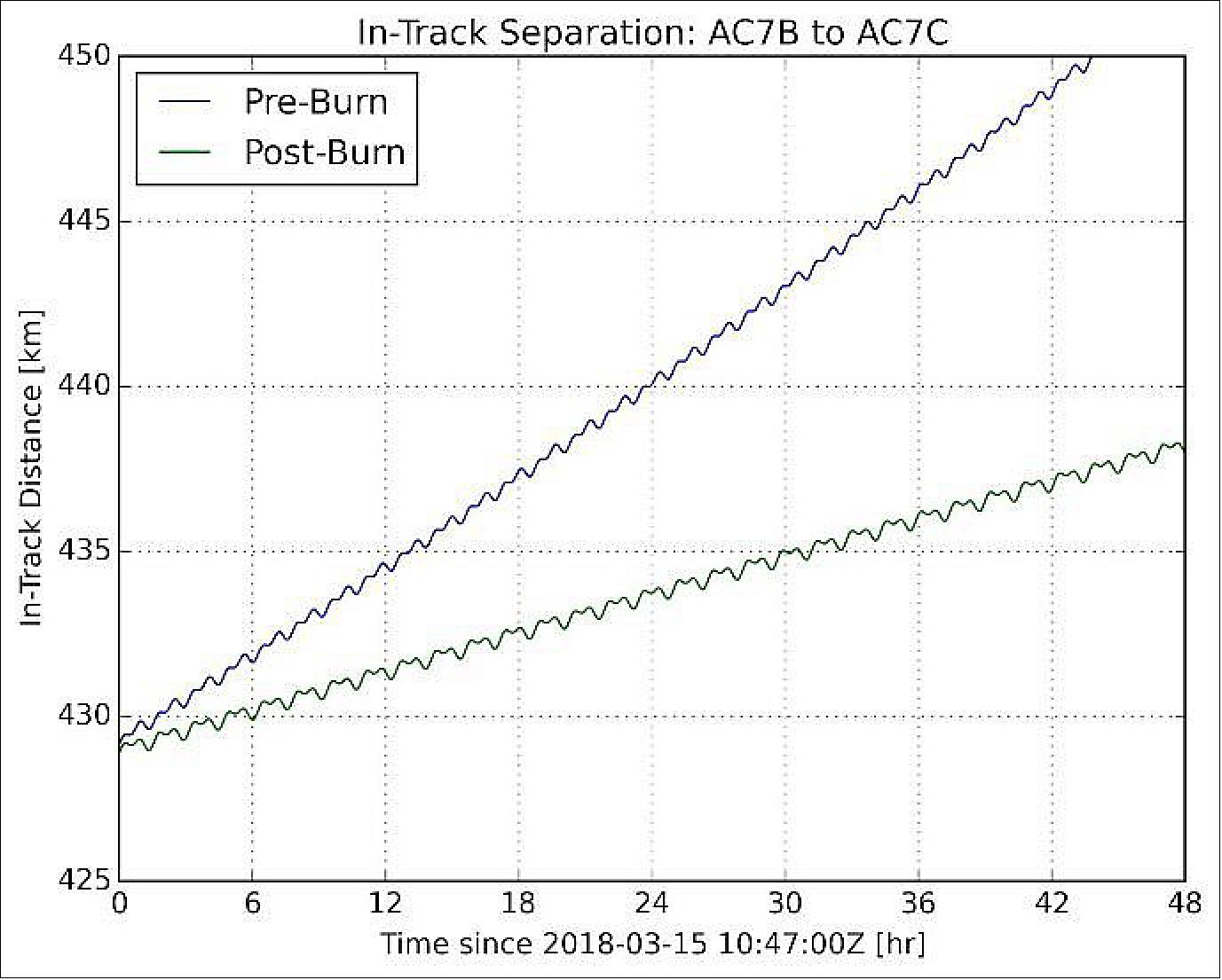
• Proximity operations (Ref. 7): On 15 March 2018, the OCSD-B CubeSat was commanded to thrust in an initial attempt to reduce the separation rate between both CubeSats. They had been ejected by the same deployer and had the same mass and dimensions, but they were separating at a rate of 11.7 km/day due to the impulse imparted by the separation springs between the two CubeSats and cumulative differences in ballistic coefficient caused by differing orientations. The original plan was to use differential air drag, but firing a thruster was faster, did not interfere with on-going optical downlink tests, and reduced mission risk. The lower risk resulted from eliminating the need to keep both spacecraft active for days on end while maintaining a fixed attitude with respect to the flight direction. The normal mode of operation is to let most spacecraft systems sleep, including attitude control, until needed for experiments, taking GPS fixes, etc. The additional propellant usage, 130 mg (milligram), was minimal; 0.5% of the propellant stored on one spacecraft.
- Figure 11 is a plot of in-track separation between the two CubeSats calculated using high-accuracy ephemerides determined by least-squares fitting to 9 separate position and velocity determinations, per orbit, by the on-board GPS receiver before and after thruster firing. The separation rate after the burn was reduced to 4.60 km/day; this represented an imparted ΔV of 2.7 cm/s.
- The next burn by AeroCube-OCSD-B, on March 22, reversed the separation and caused both spacecraft to approach each other at a rate of 2.2 km/day. Figure 12 is a plot of the calculated separation of both spacecraft as a function of time after 9 seconds of thruster firing at 48 ºC.
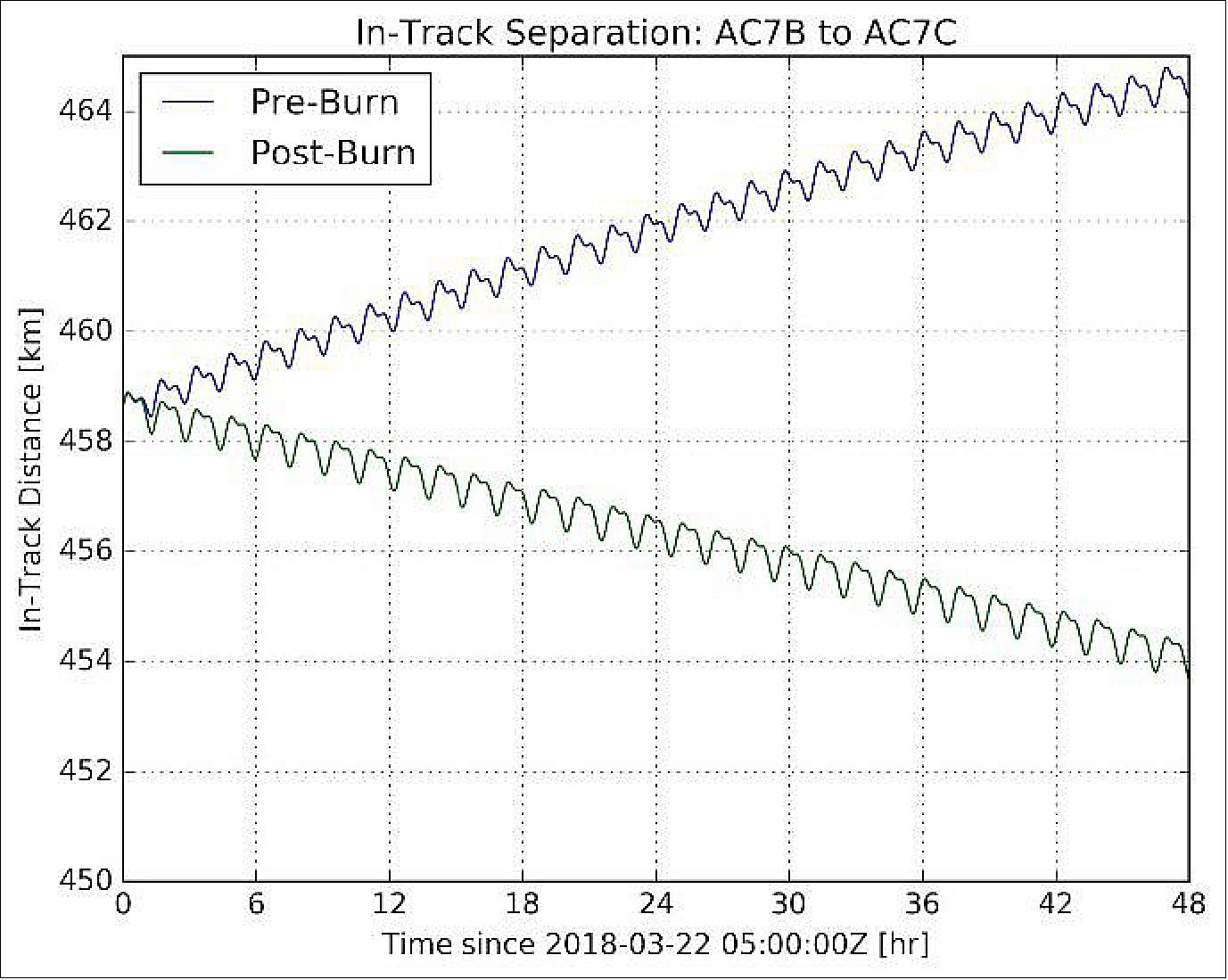
- The change in separation rate shown in Figure 12 was -5.9 cm/s, corresponding to an imparted ΔV of ~2.0 cm/s. The expected ΔV was 1.8 cm/s. The measured and expected ΔVs are 10% different, but within our measurement errors. At this post-burn rate of approach, it would take 209 days to bring the spacecraft together.
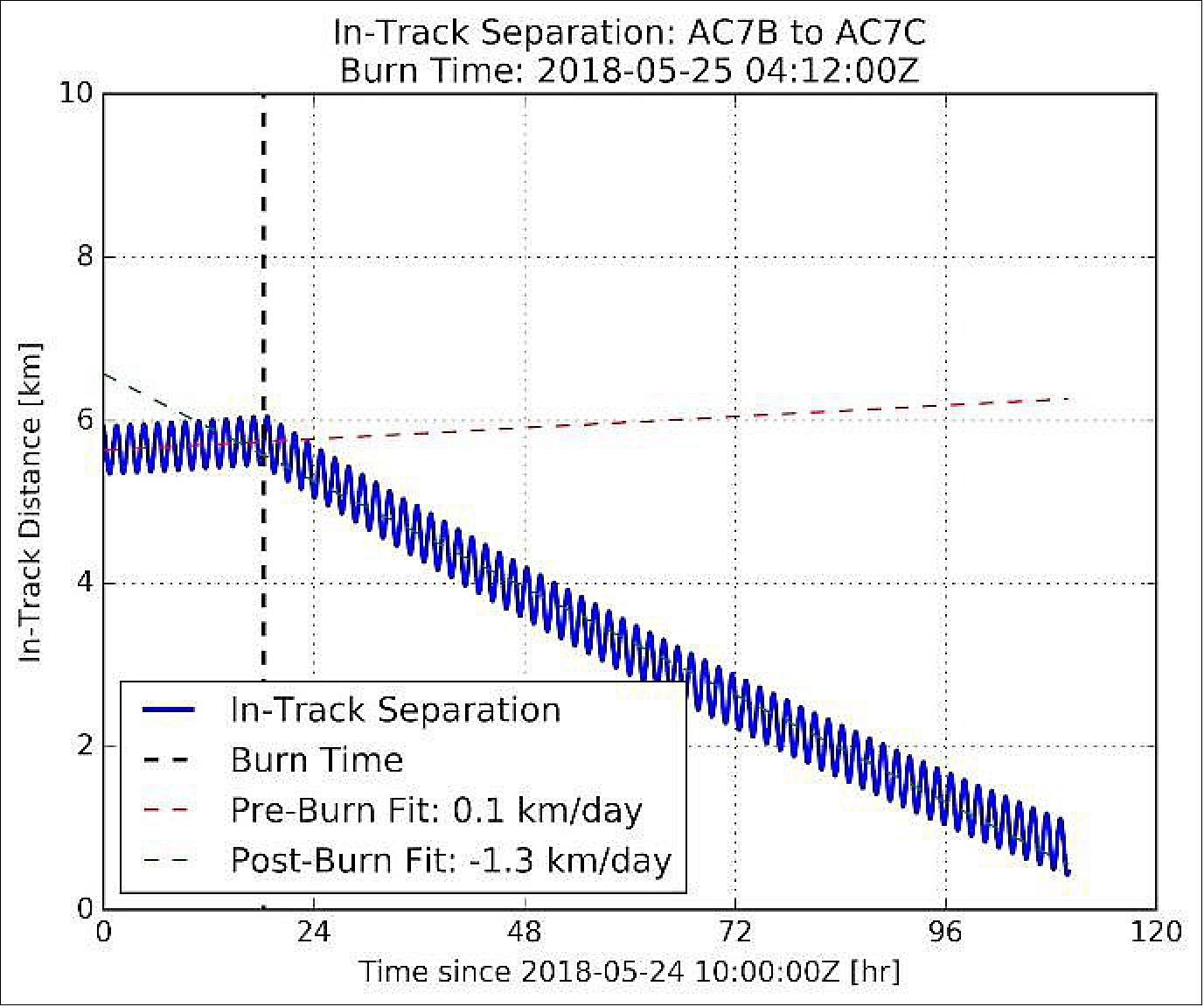
- Multiple firings occurred in April and May to adjust the approach rate and attempt a first stop at ~10 km range, and later at ~5 km range. Figure 13 is a plot of the in-track separation between the two spacecraft resulting from the thrusting maneuver that put AeroCube-OCSD-B on a trajectory to pass AeroCube-OCSD-C located at 0 km in-track distance. The ripples in this graph, and all previous range graphs, are due to slight differences in orbit eccentricity, semi-major axis, orbit inclination, etc., between both spacecraft. Each ripple period in Figure 13is an orbit period.
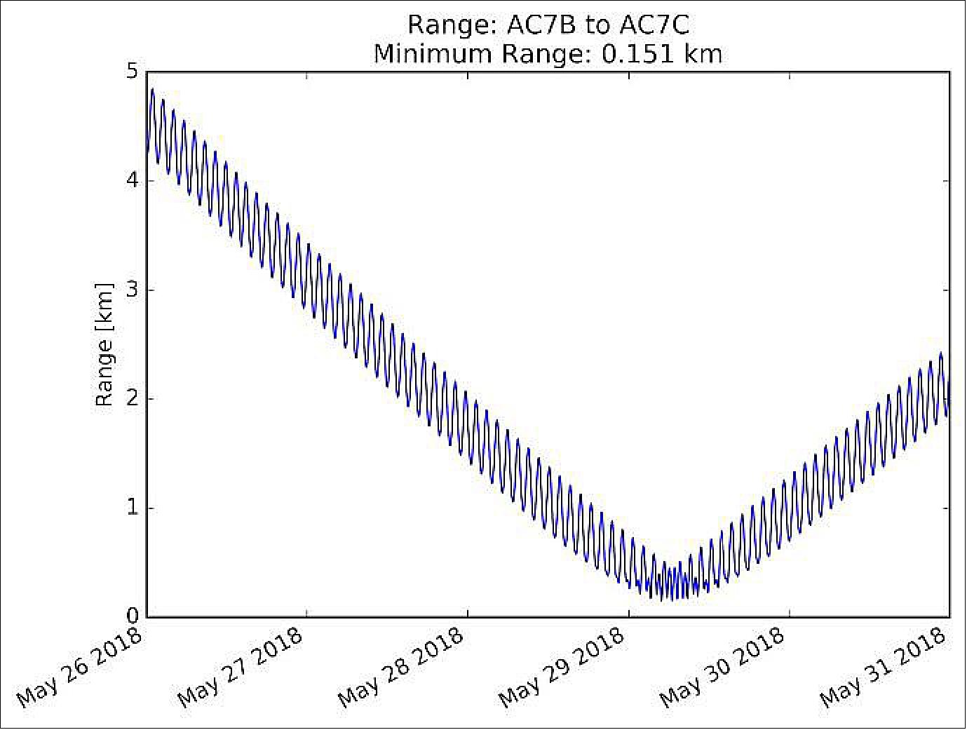
- The project's proximity operations plan was to insert one spacecraft into a co-orbital corkscrew orbit about the other, and let them slowly drift together and apart. Once properly set up with sufficient co-orbital radii, both spacecraft can be left unattended for days with little risk of collision. Figure 14 is a plot of range between spacecraft, before, during, and after closest approach on May 29. The minimum range was 151 meters!
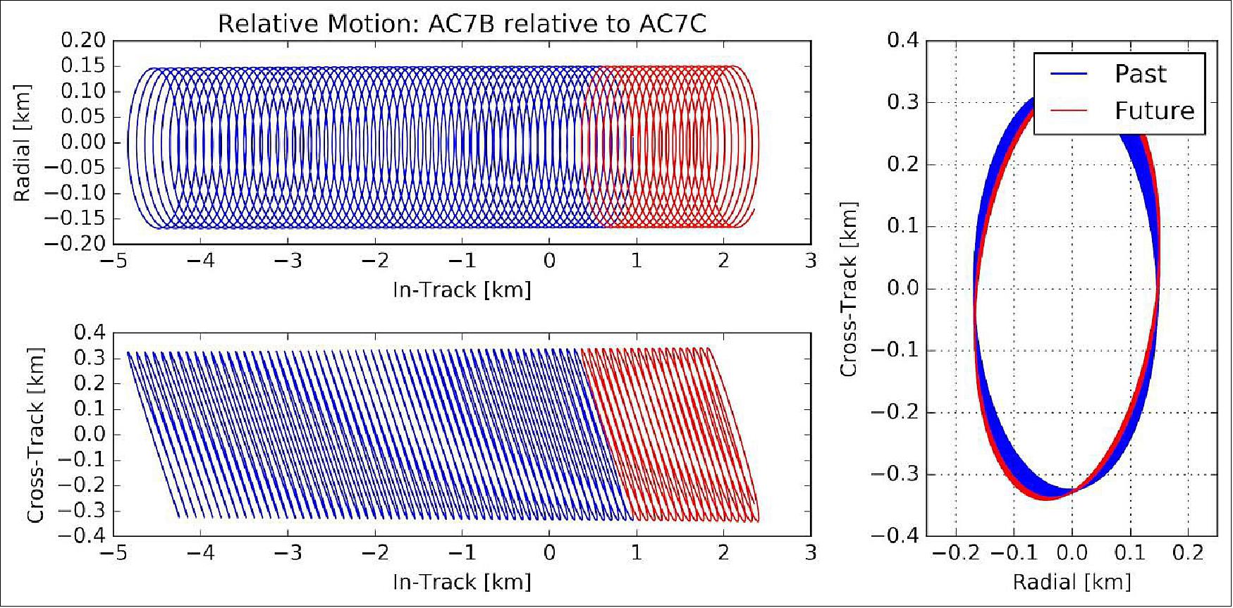
- The sinusoidal oscillations in Figures 13 and 14 indicate that the corkscrew orbit of AeroCube-OCSD-B was centered about the orbit of AeroCube-OCSD-C. Figure 11 shows the relative radial and cross-track motion of the -B CubeSat relative to the OCSD-C CubeSat, and the cross sections of the relative corkscrew co-orbit. The propulsive maneuver on May 9 (Figure 13) was set up perfectly; the OCSD-C spacecraft was in the middle of the radial and cross-track ellipse.
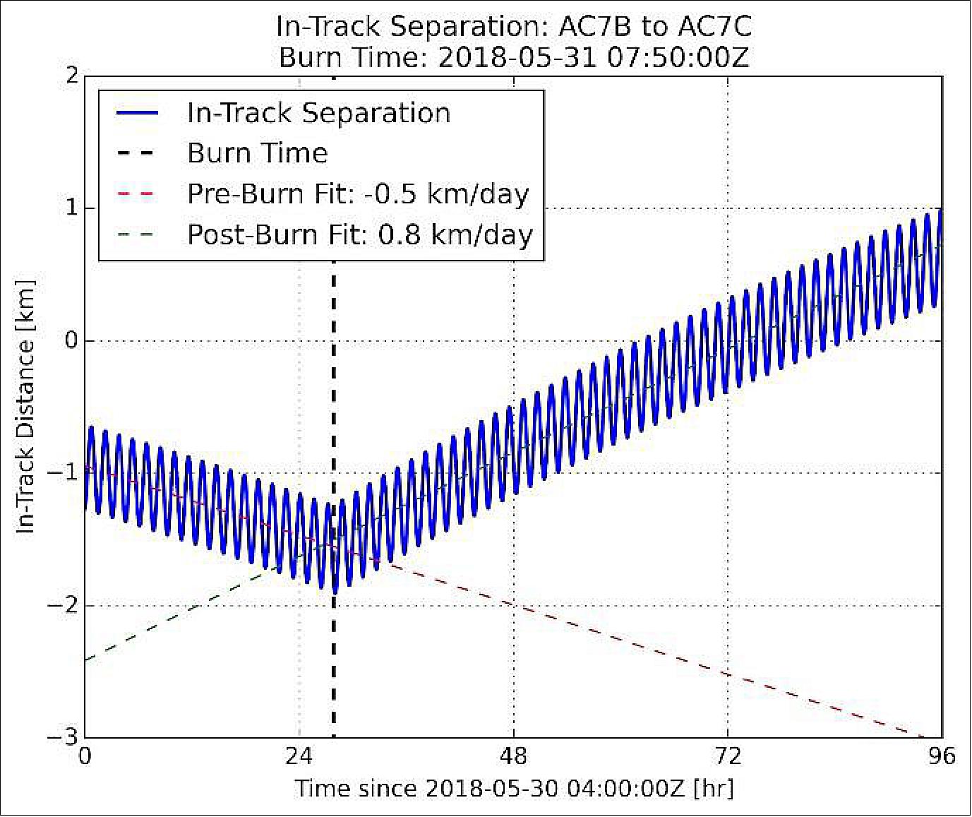
- Figure 16 shows the return burn that set up another proximity flyby on June 3, 2018 at a “leisurely” 800 m/day. To date, we have performed two more proximity flybys, and are preparing to test camera acquisition of blinking LEDs on the other spacecraft. We also plan to use the laser rangefinder on each CubeSat to provide realtime range data. The laser range accuracy is better than 1 meter, while the current GPS-fed high-accuracy ephemerides are limited to ~5 m accuracy.
- In summary, the project demonstrated the first OCSD proximity operations goal of flying one CubeSat past another in a helical co-orbit that minimizes the risk of collision between both spacecraft. We wanted to perform proximity operations without increasing the orbital debris population, and we believe these are the first CubeSats to perform this proximity operations maneuver. Proximity operations was enabled by an on-board GPS receiver and a 3-axis attitude control system with better than 0.05º pointing accuracy, originally developed for the express purpose of aiming a laser downlink in each CubeSat. It was also enabled by development of a simple steam thruster that meets CubeSat specifications, and poses minimum risk for CubeSat developers and launch vehicles. We had to vent excess pressure once on orbit, and operate at slightly higher temperatures than originally planned. Impulse bits generated by this thruster on orbit have not scaled reliably with valve “on” time and we are still trying to understand the mechanisms at work. Our next goal is to actively locate each spacecraft during a proximity operations maneuver using a color imager and flashing blue LED beacons on each CubeSat, and take range measurements using the on-board laser rangefinders. The imager should be able to see the other OCSD CubeSat at a 10 km range, and the laser rangefinder has been tested at a 2.25-km range on the ground.
• On-orbit tests of OCSD steam thrusters: Thruster firings on both spacecraft were attempted in late January, 2018. The initial attempts showed no thrust and tank pressures in excess of 500 mbar. The project suspected rapid liquid ejection due to the high tank pressure, with subsequent ice plug formation similar to what was observed in ground testing. The thruster temperature was increased to 48ºC, and the spacecraft was turned so that the sun heated the thruster nozzle. After 30 seconds of cumulative thruster operation under these conditions, the tank pressure had dropped to the vapor pressure of water. The AeroCube-OCSD-B thruster system was ready for orbit modification maneuvers on February 25, 2018, and the OCSD-C system was ready on March 3. Thruster temperature for all future maneuvers was increased to 48 ºC to minimize ice formation in the nozzle (Ref. 7).
• Deployment into orbit: The Cygnus vehicle undocked with the ISS on December 5, 2017, increased the orbit altitude to 450 km circular, and deployed 12 CubeSats, plus AeroCube-OCSD-B & -C on December 7. - This initial altitude gives the AeroCube-OCSD-B and -C our spacecraft about 2 years of orbital lifetime for laser communications and proximity operations tests (Ref. 7).
• Cygnus arrived at the station on November 14, 2017. Expedition 53 Flight Engineers Paolo Nespoli of ESA and Randy Bresnik of NASA used the space station’s robotic arm to capture Cygnus. The crew then handed robotics off to controllers on the ground for the berthing operation. Eventually, Cygnus OA-8 was berthed to Node-1 (Unity). 13) 14)
Sensor Complement
OCSD (Optical Communication and Sensor Demonstration)
Most free-space laser communication systems incorporate a complex two-axis gimbal to control beam pointing. Such gimbals are typically too massive to consider their use on small satellites, and particularly on CubeSats. The NASA-sponsored OCSD (Optical Communication and Sensor Demonstration) is a CubeSat laser-communication demonstration mission that takes a different approach by hard mounting the laser transmitter to the satellite body and pointing the laser solely with the ACS (Attitude Control System) of the spacecraft. 2) 3) Obviously this simplifies the construction of the transmitter, but it does place a burden on the ACS. On the other hand, continuing improvements in CubeSat-scale attitude control systems have led to the development of commercially-available systems that could support very useful data rates in body-mounted optical communication systems.
The OCSD program included the development of two flight units and an engineering model. Fabrication and testing of the flight units was completed in mid 2016, and they were slated to fly on a Falcon 9 in October 2016 to be deployed by the SHERPA mission. This mission was delayed and ultimately canceled as a result of the Falcon 9 launch pad fire in September 2016, and the OCSD flight units are now scheduled for launch in late 2017. The OCSD engineering model was flown as a risk reduction effort in 2015. This flight was unable to achieve all its flight objectives because of a software anomaly in the ACS, but it continues to provide a useful testbed for a number of flight systems that were first flight items, including a software-defined radio, and star cameras needed for the flight units.
Although the OCSD flight units have yet to fly, the experience gained with flying the engineering model, and with the build of the flight units, combined with the expected gain in downlink capacity generated by the optical communication system, has led to a preference for including laser communication where appropriate on future CubeSat missions being developed by Aerospace. We are currently in the final stages of building R-Cubed - a 3U CubeSat testbed for optical imaging systems that will include a communication laser to get the expected image data to the ground.11 4)
The key development that is enabling CubeSat-based laser communication systems is the rapid advance in the capabilities of CubeSat attitude-control systems. NASA published data 5) on trends in CubeSat pointing capabilities in 2015 that indicated pointing accuracies on the order of 1 degree should be possible by 2017. Instead, however, the trend is much steeper than that, and there are already commercially-available CubeSat attitude control systems advertising accuracies on the order of millidegrees. As can be seen in Figure 2, pointing accuracies in the millidegree range are sufficient for Gbit rates for LEO crosslinks and LEO-to-ground applications.
References
1) Richard Welle, Alexander Utter, Todd Rose, Jerry Fuller, Kristin Gates, Benjamin Oakes, Siegfried Janson, ”A CubeSat-Based Optical Communication Network for Low Earth Orbit,” Proceedings of the 31st Annual AIAA/USU Conference on Small Satellites, Logan UT, USA, Aug. 5-10, 2017, paper: SSC17-XI-01, URL: http://digitalcommons.usu.edu/cgi/viewcontent.cgi?article=3677&context=smallsat
2) Siegfried Janson, Richard Welle, Todd Rose, Darren Rowen, Brian Hardy, Richard Dolphus, Patrick Doyle, Addison Faler, David Chien, Andrew Chin, Geoffrey Maul, Chris Coffman, Stephen D. La Lumondiere, Nicolette I Werner, David Hinkley, ”The NASA Optical Communications and Sensor Demonstration Program: Initial Flight Results,” Proceedings of the 30th Annual AIAA/USU SmallSat Conference, Logan UT, USA, August 6-11, 2016, paper: SSC16-III-03, URL: https://digitalcommons.usu.edu/cgi/viewcontent.cgi?article=3346&context=smallsat
3) Siegfried W. Janson, Richard P. Welle, Todd S. Rose, Darren W. Rowen, David A. Hinkley, Brian S. Hardy, Stephan D. La Lumondiere, Geoffrey A. Maul, Nicolette I Werner, ”The NASA Optical Communication and Sensors Demonstration Program: Preflight Update,” Proceedings of the 29th Annual AIAA/USU Conference on Small Satellites, Logan, Utah, USA, August 8-13, 2015, paper: SSC15-III-1, URL: https://digitalcommons.usu.edu/cgi/viewcontent.cgi?article=3178&context=smallsat
4) Dee W. Pack, David R. Ardila, Eric Herman, Darren W. Rowen, Richard P. Welle, Sloane J. Wiktorowicz, Bonnie W. Hattersley, ”Two Aerospace Corporation CubeSat Remote Sensing Imagers: CUMULOS and R3,” Proceedings of the 31st Annual AIAA/USU Conference on Small Satellites, Logan UT, USA, Aug. 5-10, 2017, paper: SSC17-III-05, URL: https://digitalcommons.usu.edu/cgi
/viewcontent.cgi?article=3613&context=smallsat
5) Chad Frost, Elwood Agasid, Rogan Shimmin (editor), ”Small Spacecraft Technology State of the Art,” NASA/TP–2015–216648/REV1, NASA/ARC, 2015, URL: https://www.nasa.gov/sites/default/files/atoms/files
/small_spacecraft_technology_state_of_the_art_2015_tagged.pdf
6) ”Advancing Laser Communications Technology,” Aerospace, July 27, 2017, URL: https://aerospace.org/story/advancing-laser-communications-technology
7) Darren Rowen, Siegfried Janson, Chris Coffman, Richard Welle, David Hinkley, Brian Hardy, and Joseph Gangestad, ”The NASA Optical Communications and Sensor Demonstration Program: Proximity Operations,” Proceedings of the 32nd Annual AIAA/USU Conference on Small Satellites, Logan UT, USA, Aug. 4-9, 2018, paper: SSC18-I-05, URL: https://digitalcommons.usu.edu
/cgi/viewcontent.cgi?article=4066&context=smallsat
8) ”Aerospace CubeSats launched for optical communications memo mission,” Space Daily, Nov. 12, 2017, URL: http://www.spacedaily.com/reports/Aerospace_CubeSats_launched_
for_NASAs_Optical_Communications_and_Sensor_Demo_Mission_999.html
9) ”NASA Space Station Cargo Launches Aboard Orbital ATK Mission,” NASA, Release 17-087, 12 Nov. 2017, URL: https://www.nasa.gov/press-release
/nasa-space-station-cargo-launches-aboard-orbital-atk-mission
10) ”New COVID-19 Norms Foster Agile SmallSat Innovation,” Aerospace, 17 June 2020, URL: https://aerospace.org/article
/new-covid-19-norms-foster-agile-smallsat-innovation
11) ”NASA Demos CubeSat Laser Communications Capability,” NASA Space Tech, 9 April 2019, URL: https://www.nasa.gov/directorates/spacetech/feature/cubesat_laser_communications_capability
12) ”Laser Communications Demonstrated from CubeSats for the First Time,” The Aerospace Corporation, 2 August 2018, URL: https://aerospace.org/press-release
/laser-communications-demonstrated-cubesats-first-time
13) Stephen Clark, ”Cygnus arrives at space station with food, experiments and cache of CubeSats,” Spaceflight Now, 14 Nov. 2017, URL: https://spaceflightnow.com/2017/11/14
/cygnus-arrives-at-space-station-with-food-experiments-and-cache-of-cubesats/
14) Mark Garcia, ”Cygnus Installed on Station With New Science Experiments,” NASA, 14 Nov. 2017, URL: https://blogs.nasa.gov/spacestation/2017/11/14/cygnus-installed-on-station-with-new-science-experiments/
The information compiled and edited in this article was provided by Herbert J. Kramer from his documentation of: ”Observation of the Earth and Its Environment: Survey of Missions and Sensors” (Springer Verlag) as well as many other sources after the publication of the 4th edition in 2002. - Comments and corrections to this article are always welcome for further updates (eoportal@symbios.space).