ALL-STAR (Agile Low-cost Laboratory for Space Technology Acceleration and Research)
Non-EO
Education
Technology and Research
Quick facts
Overview
| Mission type | Non-EO |
| Launch date | 18 Apr 2014 |
| End of life date | 26 May 2014 |
ALL-STAR (Agile Low-cost Laboratory for Space Technology Acceleration and Research)
Overview Spacecraft Launch Mission Status Sensor Complement Ground Segment References
Students from the Colorado Space Grant Consortium (COSGC) have teamed with Lockheed Martin to develop a miniature satellite (3U CubeSat), known as ALL-STAR (Agile Low-cost Laboratory for Space Technology Acceleration and Research). The ALL-STAR program, designed to inspire and develop America's future technological workforce, will provide students hands-on-experience in applying science, technology, engineering and mathematics skills to building operational space systems. The ALL-STAR concept is aimed at creating a small satellite bus with increased performance parameters.
The design of the ALL-STAR (also spelled as ALLSTAR) nanosatellite bus began in January 2010, the completion of the development phase is scheduled to occur in November 2011 and delivery of the system in the spring 2012.
Lockheed Martin is supporting the program and company engineers from Sunnyvale, CA, Palo Alto, CA, Newtown, PA, Albuquerque, N.M., and Denver, CO, are supplying their system engineering, program management and systems integration expertise to mentor the COSGC students as they design, develop, manufacture and deliver the CubeSat. 1)
ALL-STAR has shown how this industry/university partnership benefits both the students and their mentors. Students gain valuable insight into aspects of spacecraft design that are not taught in classes. They also start learning about industry processes for designing, building, and testing satellites before ever working in that environment. Because of this experience, industry is getting more qualified engineers starting fresh out of college. In addition Lockheed Martin's partnership with the university will allow them to use the students to help build affordable CubeSats for internal and customer's research and development projects. 2)
COSGC, headquartered at the University of Colorado at Boulder, is a state-wide program that provides Colorado students access to space through innovative courses and real-world hands-on satellite programs. COSGC involves 16 Colorado colleges, universities and institutions and is funded by NASA as part of National Space Grant Program. 3) 4)
The ALL-STAR program is designed to accelerate the rate at which small research and technology based payloads are able to be launched by providing the satellite bus. Customers can purchase the ALL-STAR bus which includes the satellite structure, power, communications, attitude determination and control, command and data handling, and position knowledge.
Spacecraft
The ALL-STAR nanosatellite is a low-cost modular 3U CubeSat form factor bus capable of supporting the 1 year on-orbit operation of a variety of spaceborne research payloads that can be configured and ready for flight in 6 months through a simplified payload hardware and software interface.
The nanosatellite consists of fully functional subsystems operating off the same amount of power as to that of a night light, designed to support one year of on-orbit operations; the bus has a size of 10 cm x 10 cm x 34 cm with a mass of ~ 4 kg.
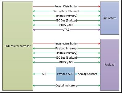
System overview: The subsystem interface has been designed so that each subsystem has an electrically identical interface to the Command and Data Handling and Flight Software systems, collectively known as CDH. The interface has three layers: the physical layer, the data link layer, and the network layer. The physical layer specification contains all requirements and details on the electrical aspect of the communication between subsystems and CDH. It will fully define the hardware interfaces need by each subsystem and CDH to complete a link. The data link layer specification details the low-level protocol needed to abstract the higher levels away from specific hardware limitations within the link. Finally, the network layer defines the high-level protocol used to transfer information and commands from one subsystem to another. This protocol forms the backbone of communication within the satellite.5) 6)
Spacecraft structure | - Standard 3U CubeSat |
EPS (Electrical Power Subsystem) | - ? 10 W nominal draw (orbit average) |
Attitude knowledge and pointing | - Knowledge accuracy: ? ±0.2o (1?) - Pointing accuracy: ? ±1o (1?) |
Position knowledge | - Onboard GPS receiver, knowledge: ? ±100 m |
Command and data handling | - Handles all subsystem interactions |
Software | Modular, easily-changeable design |
RF communications | - 250 kbit/s (min) information rate; goal of 1 Mbit/s information rate |
Optional propulsion module | - ?V of ? 10 m/s |
Mission lifetime | ? 1 year |
Spacecraft flight configuration | - Deploys solar panels and external structure |
Spacecraft flight orientation | Attitude primarily determined by the payload requirements |
STR (Structures)
The nanosatellite is comprised of three separate integrated structures (Figure 4): 8) 9) 10)
• Payload section
• Bus section
• External solar panel shell with deployable PEZ (Payload Extension Zone)
The PEZ system allows for the CubeSat to deploy its external solar array structure, exposing the internal structure and the science payload section, while still conforming to the 3U CubeSat standard during launch. In order to accomplish this, the ALL-STAR team integrated simple mechanical elements that make up the three phases of the deployment system. These phases are restraint & activation, mechanical deployment, and locking mechanisms.
Restraint & activation: The deployable solar panels are constrained during launch by three mechanisms. The first of these mechanisms is the simplest in design consisting of simply a fixed clip that is attached to the internal structure that hooks into a bracket on the back of the outermost solar panel. The middle of the solar panels are restrained through the use of a modified hinge that restrains the outer most panel from rotating away from other panel until both panels have rotated through a minimum angle. The final restraint is a rotating claw mechanism that hooks into the solar panels in the same way as the fixed clips but in distinctly different. The PEZ deployment is restrained during launch through the use of a mini-Frangibolt actuator.
The main deployment of the PEZ utilizes two constant force springs, shown in Figure 5, that are held in tension in the launch configuration. When the Frangibolt fractures, these constant force springs will begin to retract. The two structures interface through smooth sliding surfaces that allow the springs to extend the structures to the final configuration.
Once the ALL-STAR structure has fully deployed, it is important that the satellite remains as ridged as possible and that the mechanisms for the deployment don't collapse. To prevent such events, the mechanical team has also incorporated several locking mechanisms. The first mechanism is an integrated spring plunger and hard stop on the external structure. The hard stop insures that the constant force springs can't over deploy the structure to a point in which the structures would separate. Also the integrated spring plunger falls into a locking hole that insures that the structures don't re-collapse.
ADCS (Attitude Determination and Control Subsystem)
ADCS, also referred to as ACS, provides 3-axis spacecraft stabilization. Attitude sensing is provided by a 3-axis magnetometer, a star tracker, and gyroscopes; actuation is provided by reaction wheels (3 wheels mounted orthogonally) and magnetorquer wheels (used for momentum dumping). ADCS is capable is support of the following maneuvers:
• Ground target tracking: short duration, quickly changing the target vector (> 60o in < 10 minutes)
• Sun spin:
- Perform spin with minimal losses (zenith within 10o of sun vector)
- For orbital altitude of 350 km: 5 min for 180o
• Change of target vectors: (used for payload pointing and RF communications)
- 2 minutes (~2.5% of orbit)
- 75o half angular distance across Earth
• Correct external torques: Max aerodynamic torque of ~6 x 10⁻⁵ Nm @ 350 km altitude.
ADCS microcontroller: AVR32UC3 (commonality with CDH)
• Tracks attitude knowledge and commands
• Implements control law and controls actuators
• SPI (Serial Peripheral Interface)
- Receive inertial reference from star camera
- Read gyroscope ADC
- Command motor and magnetorquer controllers
• Two wire interface(I2C): Read magnetometer.
Star tracker:
• Provides inertial attitude reference to attitude determination system
• Built in-house due to cost constraints
• Image processing and star identification performed using a dedicated FPGA (Field Programmable Gate Array).
GPS receiver:
• Selection of the COTS GPS receiver, the Novatel OEMV-1.
• GPS antenna: VTGPSIA-3 antenna with built in LNA
• The receiver provides both position and time solutions to the onboard subsystems.
CDH (Command and Data Handling) Subsystem
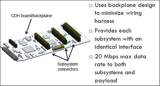
The CDH subsystem provides wire-free integration with subsystems and payload.
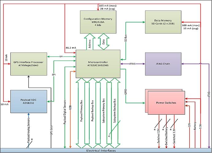
• Provides 32-bit microcontroller to FSW (Flight Software). Also utilizes 8-bit microcontroller for interface support to power switching components and GPS
• MRAM (Magnetoresistive Random-Access Memory) provides flexible SRAM (Static Random Access Memory ) extension / configuration storage space
• Micro SD (Secure Digital) cards allow for expandable storage in small form factor.
• Interfaces:
- Provide each subsystem an identical electrical interface
- Payload supplied data bus, digital and analog sensors/indicators
- System watchdog helps mitigate SEUs (Single Event Upsets) and other lockup conditions
- 1-Wire temperature bus allows temperature sensing with satellite unpowered.
Component | Manufacturer | Model | Temperature range |
Microcontroller | Atmel | AT32UC3A3256S | -40oC to +85oC |
GSE Interface | FTDI | FT2232H | -40oC to +85oC |
Data memory | Kingston | 2 GB SD | -25oC to +85oC |
Configuration memory | Everspin | MR2A16ACYS35 | -40oC to +85oC |
Payload ADC | Texas Instruments | ADS8332 | -40oC to +85oC |
GPS interface microcontroller | Atmel | ATXMega256A3 | -40oC to +85oC |
Subsystem connector | Samtec | LS2-125-01-S-D –RA1 | N/A |
Backplane connector | Samtec | LS2-125-01-S-D | N/A |
EPS (Electrical Power Subsystem)
EPS design features:
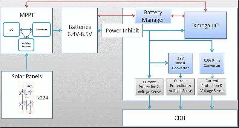
• 10 W nominal power (5 W to the bus, 5 W to the payload)
• 30 W peak power (in COM passes, etc.) for 15 minutes / 2 orbit
• Total of 918 solar cells: (cell efficiency of 27%)
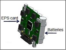
• 4 Li-Ion battery cells, 2 sets in parallel; cell capacity of 2.6 Ah at 3.65 V each
• The power bus is divided into 3.3 V and 12 V unregulated battery lines
• Solar interface: MPPT (Maximum Power Point Tracking) from solar cells to batteries.
• The EPS is monitored and controlled by the master processor.
RF Communications
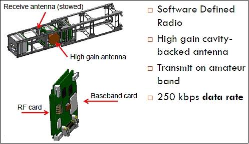
A full duplex communications subsystem is implemented, featuring SDR (Software Defined Radio) architecture, S-band (2.41 GHz) downlink with a data rate of 250 kbit/s with BPSK (Binary Phase Shift Keying) modulation and convolutional coding (Reed Solomon). The uplink is in UHF (435 MHz) with a data rate of 9.6 kbit/s. In addition, a CW beacon is implemented.
PROP (Propulsion Subsystem)
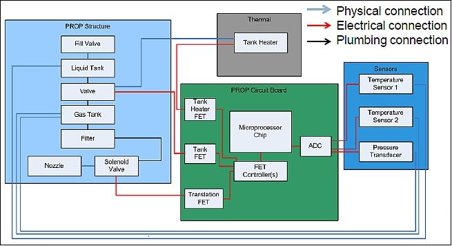
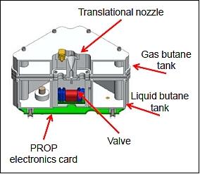
PROP is an optional independent module that can be attached to the payload section of the ALL-STAR bus. The PROP design features and capabilities are:
• A cold gas propulsion system (butane propellant with a mass of 72 g)
• 1 valve/nozzle provides 0.05 N of thrust
• Achieve a minimum ?V of 10 m/s
• Approximate time for ?V of 10 m/s is 190 minutes.
The total mass budget of PROP is 485 gram.
Launch
ALL-STAR-1 was selected as a secondary payload to participate in NASA's ELaNa-5 (Educational Launch of Nanosatellites-5) initiative, and has been manifested on the CRS-3 (Commercial Resupply Services-3) mission to the ISS on a Falcon 9 V1.1 launcher/Dragon spacecraft of SpaceX. ALL-STAR-1 was launched on April 18, 2014. The launch site was Cape Canaveral, FL. 12) 13) 14)
Orbit: Near-circular orbit, altitude of ~350-400 km, inclination = 51.6o, period: ~ 91 minutes.
Cargo of CRS-3: Dragon will be filled with about 2090 kg of supplies and payloads, including critical materials to support more than 150 investigations that will occur during Expeditions 39 and 40. Dragon will carry four powered cargo payloads in its pressurized section and two in its unpressurized trunk, a first for SpaceX. Dragon will return with about 1630 kg of cargo, which includes crew supplies, hardware and computer resources, science experiments, biotechnology, and space station hardware.
The science payloads include:
• OPALS (Optical Payload for Lasercomm Science), which will test the use of laser optics to transfer information to Earth from space.
• VEGGIE (Vegetable Production System), a unit capable of producing salad-type vegetables in space.
• T-Cell Activation in Aging experiment that seeks the cause of a depression in the human immune system while astronauts are in microgravity.
• In addition, the HDEV (High Definition Earth Viewing) investigation includes four high-definition cameras to be placed on the space station's exterior for use in streaming live video of Earth for online viewing.
Secondary payloads: The secondary payloads (4 nanosatellites and 1 CubeSat) were contained in four P-PODs (Poly Picosatellite Orbital Deployers) and installed on the second stage of the Falcon 9 launcher. These secondary payloads were not being delivered to the ISS, but released from their P-PODs following the separation of the Dragon capsule from the second stage (~10.5 minutes after liftoff). The insertion orbit of the secondary payloads was at an altitude of ~325 km with an inclination of ~51.6o. 15)
The secondary payloads were part of the fifth installment of NASA's ELaNa (Educational Launch of Nanosatellite) mission. Over 120 students have been involved in the design, development and construction of all the CubeSats that were flown as auxiliary payloads on the SpaceX-3 cargo resupply mission. 16)
• KickSat, a 3U CubeSat of Cornell University, N.Y., USA. KickSat will carry and attempt to deploy about 250 femtosatellites into LEO (Low Earth Orbit).
• All-Star/THEIA, a 3U CubeSat of COSGC (Colorado Space Grant Consortium).
• SporeSat, a 3U CubeSat (~5.5 kg) developed through a partnership between NASAs Ames Research Center and the Department of Agricultural and Biological Engineering at Purdue University. SporeSat will be used to conduct scientific experiments to gain a deeper knowledge of the mechanisms of plant cell gravity sensing.
• TSAT (TestSat-Lite), a 2U CubeSat developed at Taylor University of Upland, Indiana. The objective is to perform measurements of the temperature and density of the plasma in the near-Earth space environment.
• PhoneSat-2.5, a technology 1U CubeSat of NASA/ARC to continue technology demonstrations of the PhoneSat CubeSat series.
Mission Status
• ALL-STAR/THEIA officially deorbited on Memorial Day, May 26th, 2014. The ALL-STAR team here at Space Grant is now working on post-mission analysis and going through available data and observations. The team is looking to learn from their experience with ALL-STAR and improve the next iterations of the ALL-STAR bus system. 17)
• Unfortunately no communications with the ALL-STAR CubeSat have yet been confirmed. Several sightings of the beacon carrier signal at 2.4017 GHz appear promising, but no data has yet been recovered. This is partly due to a component malfunction at the local Longmont, CO ground station on April 22, 2014 that crippled the ground station tracking capabilities for the duration of the mission.
- In light of this, the ALL-STAR team reached out to several other collaborators with S-band ground station equipment and received an overwhelming amount of support and enthusiasm in helping to track our satellite, both with S-band receivers and optical telescopes.
• The 3U CubeSat was inserted into a roughly circular orbit at 325 km altitude, 51.7o inclination. Due to the large amounts of drag in the low-earth orbit, the mission lifetime is expected to be very short, about 4-6 weeks long. ALL-STAR/THEIA is currently projected to deorbit around May 23-25, 2014. 18)
Sensor Complement
THEIA (Telescopic High-definition Earth Imaging Apparatus)
THEIA, named for the titan goddess of sight in Greek mythology, is an optical remote sensing payload, compatible with the COSGC ALL-STAR bus, that will take images of Earth's surface in full color in order to verify all capabilities of the ALL-STAR bus on orbit, providing a marketable proof of concept. 19) 20) 21) 22) 23)
The THEIA instrument is being designed and developed by the THEIA team at the University of Colorado (UC) and at COSGC (Colorado Space Grant Consortium).
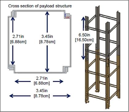
THEIA must meet the mass and volume constraints, as stated in the ALL-STAR ICD (Interface Control Document). The payload constraints of the ALL-STAR bus structure are:
• Volume (max): 1215 cm3
• Length (max): 16.5 cm (payload+ PROP)
• Mass (max): 2 kg (including the payload structure).
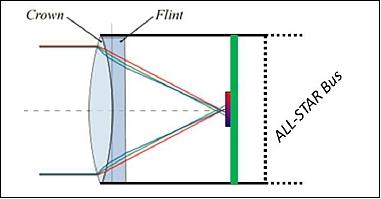
The THEIA imaging system is comprised of a refractor and a CMOS imaging sensor. The refractor chosen for this design is an achromatic doublet lens that measures 50.8 mm in diameter and has a 150 mm focal length. An achromatic doublet lens is composed of two lenses that made of two types of glass that are cemented together with optical-grade adhesive, as shown in Figure 20. Placing two types of lenses in extremely close proximity is a common optical practice for image clarity since the second lens effectively reverses the prism effect of the first. Furthermore, the diameter and focal of the chosen refractor fits within the volume constraints, but utilizes of the majority of the allotted volume to achieve the required angular resolution and field of view.
Baseline mission:
• 50 mm aperture refractor telescope
• Full color, Earth imaging (spectral range: 0.4-1.0 µm)
• 1o FOV (Field of View)
• Required angular resolution of 0.04o
• Goal angular resolution of 0.0017o
• 5 Mpixel CMOS camera.
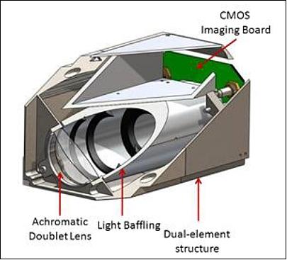
The full structural system design is shown in Figure 21 with the key components of the THEIA design labeled. The payload structure is a dual-element structure with nearly equal lengths of Invar-36 and Titanium-64. The thermal expansion and compression of this dual-element structure closely follows the change in focal length of the optics system with temperature. Furthermore, the light baffle structure can be seen between the refractor and the imaging sensor. Within the structure, four light baffles are used to eliminate off-axis light that enters THEIA from the edge of the refractor.
The lens and electronics mounting is also visible. The single optic will be mounted with Invar-36, which exhibits minimal expansion with temperature and will produce minimal rotational and translational misalignment at differing temperatures. The CMOS board is mounted at the focal point of the refractor, and the FPGA is in its own housing structure on one side of the structure. FPGA is mounted on the side of THEIA to allow for maximum focal length between the refractor and imaging sensor.
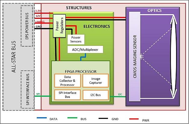
The system functional block diagram is displayed in Figure 22. It can be seen that the ALL-STAR bus provides 3.3 V, 12 V, and unregulated battery power line to THEIA. THEIA will then regulate and distribute the provided to the CMOS imaging sensor, the FPGA processor, and supporting electronics. When THEIA is taking an image, incoming light will be focused on the imaging sensor by the refractor and captured with the imaging sensor's electronic shutter. The image will then be sent over I2C interface to the FPGA, which will process the image. Finally, the processed image and sensor data will be transferred to the ALL-STAR bus over an SPI interface and saved. On orbit, the ALL-STAR bus will downlink the data on the next available ground pass.
Concept of operations:
The THEIA project has three separate concepts of operations, depending on the situation at hand. The first concept of operations describes the imaging process of the THEIA system, and can be seen in Figure 23. Note that the process repeats itself every time an image is taken at the maximum rate of one image per minute.
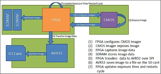
In orbit, the ALL-STAR bus will orient in the direction of the desired object (target area) before THEIA captures an image. After THEIA captures an image, THEIA will transfer the processed image to the ALL-STAR bus, which will store the image until the next COM pass when it will downlink the processed image.
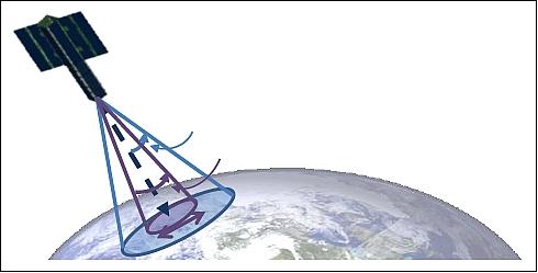
In order to validate the pointing capabilities and pointing knowledge of the bus, the payload must be able to see the desired target even if the bus is off by its maximum error which is 1o. Figure 24 illustrates how the FOV is related to the pointing accuracy of the ALL-STAR bus and what this covers on the ground. The pointing knowledge of the ALL-STAR bus can be validated if the resolution of the telescope is around 5 times better than the bus' knowledge. Therefore the angular resolution of the telescope must be at least 0.04o. The goal however is to be able to see much finer detail than what would be seen with 0.04o of angular resolution, so an additional stretch goal requirement was set based around the goal of seeing a football field sized object on the ground.
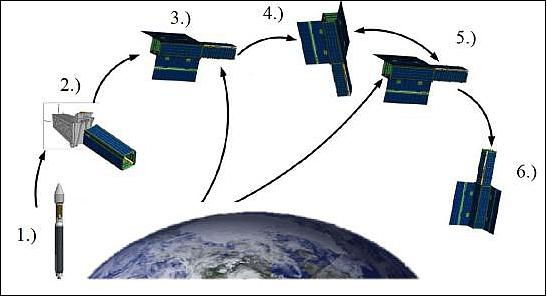
1) Launch
2) ALL-STAR start-up mode
• The ALL-STAR bus is deployed from P-POD and launch vehicle
• The ALL-STAR bus solar panels receive power and deploy. The ALL-STAR bus subsystems turn on and check health and status
• During the first high speed COM pass, the ground operator checks health and status of the ALL-STAR bus and approves it for normal operation.
3) COM (communications) pass 2
• The ground operator turns on THEIA
• The health and status of THEIA is checked by CDH and relayed to the ground.
4) Payload operations mode
• The ALL-STAR bus identifies when the satellite approaches the desired picture location, and points THEIA to the ground
• THEIA takes multiple pictures of the ground
• THEIA processes images and sends data to the ALL-STAR bus
• The ALL-STAR bus returns to nominal Nadir attitude.
5) Typical COM pass mode
• The ALL-STAR bus sends health and status of the ALL-STAR bus and THEIA
• The ALL-STAR bus sends processed images, data, and corresponding GPS location to ground station
6) End of life
• The ALL-STAR bus attitude system orients ALL-STAR to maximize drag
• The ALL-STAR bus and THEIA are shut down.
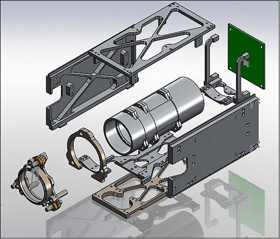
Legend to Figure 26: The left side displays the optics lens mounting which attaches to the light baffle assembly. At the end of the light baffle tube is the CMOS image sensor board (green). The optics assembly is supported by an invar plate (brown, bottom of picture) and is housed in aluminum.
Ground Segment
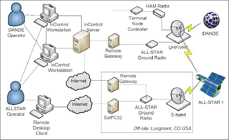
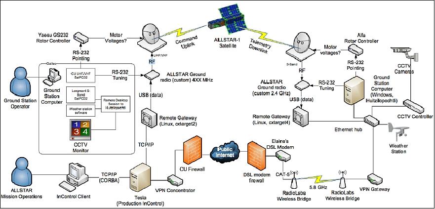
The ground station for ALL-STAR is operated by students at the University of Colorado at Boulder and is physically located about 15 miles from campus near Longmont, CO. 24)
The station consists of a 3 m parabolic dish with a small circularly polarized patch antenna feed at the focus for the S-band link (satellite to ground) and a 1 m circularly polarized Yagi antenna mounted to the top of the dish for the UHF link (ground to satellite).
The S-band LNA at the receive feed point boosts the S-band signal to the electronics shed near the dish. A power amplifier in the electronics shed boosts the Software Defined Ground Radio signal to the Yagi transmit antenna. The RF COM, digital COM, and digital COM to Ethernet boards are also located in the electronics shed.
The S-band LNA at the receive feed point boosts the S-band signal to the electronics shed near the dish. A power amplifier in the electronics shed boosts the Software Defined Ground Radio signal to the Yagi transmit antenna. The RF COM, digital COM, and digital COM to Ethernet boards are also located in the electronics shed.
The ALL-STAR-1 mission is embedded in a distributed ground segment of COSGC (Colorado Space Grant Consortium) to serve a number of educational nanosatellite missions of the University of Colorado (ALL-STAR, DANDE, HERMES-2, etc.). 25)
References
1) "Colorado Space Grant Consortium, Lockheed Martin To Develop CubeSat," Lockheed Martin, Aug. 10, 2010, URL: http://www.lockheedmartin.com/us/news/press-releases
/2010/august/ColoradoSpaceGrantConsort.html
2) Jessica Brown, Mark Wolfson, "Hands-on education through student-industry partnerships," 2013, URL: http://www.amostech.com/TechnicalPapers/2013/POSTER/WOLFSON.pdf
3) http://spacegrant.colorado.edu/images/AllStar/Story%20Board.pdf
4) http://spacegrant.colorado.edu/boulderstudents/boulderprojects/allstar
5) Jessica Brown, Riley Pack, Tyler Murphy, Ryan Kophs, "Systems and Management Backup Documentation," ALL-STAR System Requirements, SYS.200.2, Jan. 3, 2011
6) Tyler Murphy, Jon Kanaber, Chris Koehler, "PEZ: Expanding CubeSat Capabilities through Innovative Mechanism Design," Proceedings of the 25th Annual AIAA/USU Conference on Small Satellites, Logan, UT, USA, Aug. 8-11, 2011, paper: SSC11-XII-5, URL of paper: http://digitalcommons.usu.edu/cgi/viewcontent.cgi?article=1179&context=smallsat, URL of presentation: http://digitalcommons.usu.edu/cgi/viewcontent.cgi?filename=0&article=1179&context=smallsat&type=additional
7) Jessica Brown, Riley Pack, Tyler Murphy, Ryan Kophs, "Systems and Management," Critical Design Review Slides
8) Simon Hodgson, Jon Kanaber, Matt Gosche, "Structures and Mechanisms," Critical Design Review Slides
9) Isaac Hayden, "STR Overview," URL: http://spacegrant.colorado.edu/images/AllStar/STR.pdf
10) Jessica Brown, "ALL-STAR Microgravity Structural Deployment and Attitude Control Test," COSGC, Oct. 27, 2010, URL: http://spacegrant.colorado.edu/images/stories/ALL-STAR/ALL-STAR
_Microgravity_Proposal.pdf
11) "ALL-STAR System Integration Review," COSGC, April 19, 2013, URL: http://spacegrant.colorado.edu/images/AllStar/ALLSTAR_SIR_Slides.pdf
12) "ALL-STAR Projects - Colorado Space Grant Consortium," URL:http://www.nasa.gov/mission_pages/station/structure/launch/#.U1ZuzaKegkB
13) SpaceX Launch to Space Station Reset for March 30, NASA, March 21, 2014, URL: http://www.nasa.gov/mission_pages/station/structure/launch/#.UwS1s87ihqP
14) "NASA Press Kit, March 2014, SpaceX CRS-3 Mission," NASA, URL: http://www.nasa.gov/sites/default/files/files/SpaceXCRS-3_PressKit_FINAL.pdf
15) Patrick Blau, "Dragon SpX-3 Cargo Overview," Spaceflight 101, URL: http://www.spaceflight101.com/dragon-spx-3-cargo-overview.html
16) "ELaNa V CubeSat Launch on SpaceX-3 Mission," NASA Facts, March 2014, URL: http://www.nasa.gov/sites/default/files/files/ELaNa-V-Factsheet-508.pdf
17) http://spacegrant.colorado.edu/boulderstudents/boulderprojects/allstar
18) "ALL-STAR/ThEIA," URL: http://spacegrant.colorado.edu/allstar-projects/theia
19) Christopher Koehler, Scott Palo, Herbert Kroehl, Jean Koster, Russ Mellon, Peter Bradley, Jessica Brown, Justin Clark, Nicole Doyle, Kyle Florentine, Kyle Kemble, Carolyn Maurus, Jennifer McGraw, Brian Roth, Malcolm Young, "Telescopic High-definition Earth Imaging Apparatus (THEIA)," Project Final Report (PFR), April 28th, 2010
20) "Telescopic High-definition Earth Imaging Apparatus (THEIA), Conceptual Design Document," University of Colorado, Sept. 23, 2010
21) "Telescopic High-definition Earth Imaging Apparatus," CDR (Critical Design Review), Dec. 1, 2010
22) "THEIA - Telescopic High-definition Earth Imaging Apparatus," Project Definition Document (PDD), Sept. 9, 2010
23) "An Athermal System Design to Improve Optical Performance across a Mission Profile," April 9, 2011
24) ALL-STAR Ground Station Overview, Revised July 31, 2013, URL: http://spacegrant.colorado.edu/images/AllStar/GndStationOverview.pdf
25) Quinn McGehan, Michael Mozingo, Megan O'Sullivan, Michael Trowbridge, "A Distributed Common Ground Segment for Educational Nanosatellites," 2012 COSGC Space Research Symposium, April 19, 2012, URL: http://spacegrant.colorado.edu/COSGC_Projects/symposium/2012/07_Distributed%20Ground%20Segment.pdf
26) Vignesh Muralidharan, Michael Trowbridge, Quinn McGehan, Bill Irelan, Logan Smith, "Strategies for rapid design and development of ALL-STAR-1 ground segment," 10th Annual CubeSat Developers' Workshop 2013, Cal Poly, San Luis Obispo, April 24-26, 2013, URL: https://web.archive.org/web/20190716162211/http://mstl.atl.calpoly.edu/~bklofas/Presentations/DevelopersWorkshop2013/Muralidharan_ALLSTAR-1.pdf
The information compiled and edited in this article was provided by Herbert J. Kramer from his documentation of: "Observation of the Earth and Its Environment: Survey of Missions and Sensors" (Springer Verlag) as well as many other sources after the publication of the 4th edition in 2002. - Comments and corrections to this article are always welcome for further updates (eoportal@symbios.space)
Overview Spacecraft Launch Mission Status Sensor Complement Ground Segment References Back to top