BRITE (BRIght-star Target Explorer) Canada
Non-EO
Operational (extended)
Astronomy and Telescopes
Quick facts
Overview
| Mission type | Non-EO |
| Mission status | Operational (extended) |
| Launch date | 19 Jun 2014 |
BRITE (BRIght-star Target Explorer) Constellation / BRITE Canada
Spacecraft Launch Mission Status Sensor Complement Concept and Software References
The BRITE constellation is a truly international mission. The original mission concept for BRITE was developed by the Canadian astronomer, Slavek M. Rucinski of the Department of Astronomy at the University of Toronto, as a nanosatellite follow-on to the highly successful MOST (Microvariability and Oscillations of Stars) microsatellite stellar photometry mission. Since BRITE was conceived, the single-satellite mission concept has grown to a six satellite constellation with science teams, engineering teams and funding sources in Canada, Austria and Poland. 1) 2)
Science objective: The primary mission objective of BRITE Constellation is to provide milli-magnitude (0.1% error) differential photometry of bright stars. It so happens that, in Earth's sky at least, the most apparently bright stars are also among the most intrinsically bright stars. These stars, and in particular the AGB (Asymptotic Giant Branch ) and OB stars (OB stars are hot, massive stars of spectral types O or B which form in loosely organized groups called OB associations), most affect the ecology of the universe by creating and distributing all of the heavy elements that are necessary for life as we know it.
Despite their prominence in the sky, bright stars have not been studied to the same extent as fainter stars. As such, there remain several questions about the life cycles of these stars that BRITE Constellation hopes to help answer using photometry/asteroseismology. The ultimate goal for BRITE is to be able to provide photometric data on all 286 stars brighter than visual magnitude +3.5.
Mission concept: It is well known that massive stars experience periodic, semi-periodic and irregular variations in intensity due to factors such as change in density, magnetic field, surface temperature and internal seismic phenomena. The periods associated with these variations can range from minutes to months. BRITE Constellation fills an observational niche by providing scientists with almost continuous precise photometric time-series measurements with very long baselines (up to six months). By identifying the modes astronomers are able to extract information regarding the internal structure and density profile of these stars.
To achieve its goals, each BRITE satellite will take stellar photometric measurements of a target star field at least 15 minutes per orbit, every orbit, for up to six months at a time. To do this, each satellite in the constellation is equipped with a wide field of view (FOV) optical instrument (24º x 19º). The wide FOV ensures almost 100% coverage of the sky for differential photometry of the target stars.
Background
• The BRITE Constellation began in earnest in 2005 when a single BRITE satellite (UniBRITE) was funded by the University of Vienna, Austria. The collaborative UniBRITE mission with UTIAS/SFL (University of Toronto, Institute for Aerospace Studies/Space Flight Laboratory) was also to be built and integrated by SFL.
• Funding for a second Austrian BRITE satellite (BRITE-Austria, aka TUGSat-1) was secured in January 2006, this time funded by the Austrian Space Agency, named FFG/ALR (Forschungsförderungsgesellschaft/Agentur für Luft- und Raumfahrt), Vienna, Austria. Unlike UniBRITE, BRITE-Austria would be assembled and tested in Austria by engineers at the Technical University of Graz (TUG) using a kit of parts and with mentorship from SFL. While each Austrian BRITE satellite would carry a payload tuned to a different optical band the satellites were otherwise almost identical.
• The third and fourth BRITE satellites were funded several years later, in 2010, by Poland. Like BRITE Austria, the Polish satellites are being assembled and tested at the Space Research Center in Warsaw from a kit of parts delivered by SFL. The last pieces of that kit were delivered to Warsaw in June 2011. The first Polish BRITE is a copy of BRITE-Austria in that it carries the Blue version of the BRITE instrument. The second Polish satellite may carry an ultraviolet (UV) version of the BRITE instrument, pending a favorable feasibility study.
• BRITE Canada represents the third entry into the BRITE constellation. After several delays, the fifth and sixth BRITE satellites were finally funded by the Canadian Space Agency (CSA) in January of 2011, ensuring full Canadian participation in what was originally a Canadian idea. The Canadian BRITE satellites, currently under construction at UTIAS/SFL, will be almost identical copies of the two Austrian BRITE satellites.
Spacecraft
All spacecraft in the constellation use the GNB (Generic Nanosatellite Bus) platform, referred to as CanX-3, were developed at UTIAS/SFL.
The reader is referred to the spacecraft description of BRITE Austria / UniBRITE.
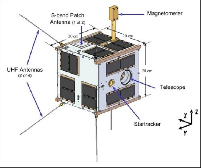

Spacecraft mass, volume, total power | 6.5 kg, 20 cm x 20 cm x 20 cm, 5.4-10 W (6 W average) |
Bus voltage | 4.0 V (nominal, unregulated) |
Solar cells | Triple junction solar cells (face mounted) |
Battery type, capacity | Li-ion, 5.3 Ah |
Attitude determination | 10 arcsec |
Attitude control accuracy, stability | < 1.0º, 1 arcmin rms (or FWHM of ~2.2 arcmin) |
Onboard payload data storage | Up to 256 MByte |
RF communications |
|
Mission duration | 2 years (min) |
Launch
The two Canadian BRITE/CanX-3 nanosatellites (BRITE-CA-1 and BRITE-CA-2), were launched as secondary payloads on June 19, 2014 (19:11:11 UTC) on a Dnepr-1 vehicle of ISC Kosmotras. The launch site was the Yasny Cosmodrome in the Dombarovsky region of Russia. 3) 4) 5)
The primary payloads on this flight were the Deimos-2 minisatellite (310 kg) of Deimos Elecnor, Spain, and the KazEOSat-2 minisatellite (185 kg) of Kazcosmos, Kazakhstan.
The secondary payloads (35) on this Dnepr cluster mission were: 6)
• UNISat-6, a microsatellite of GAUSS at the University of Rome (La Sapienza), Italy. UniSat-6 (26 kg) includes Pico-Orbital Deployers and PEPPODs (Planted Elementary Platform for Picosatellite Orbital Deployment) systems for the release of four CubeSats from the spacecraft. These four satellites are:
- Lemur-1, a 3U CubeSat (technology demonstration and EO) of NanoSatisfi Inc., San Francisco, CA, USA
- TigriSat, a 3U CubeSat of the University of Rome (La Sapienza), Rome, Italy.
- ANTELSAT, a 2U CubeSat of UdelaR (University of the Republic), San Marino, Uruguay
- AeroCube-6, a 1U CubeSat of The Aerospace Corporation, El Segundo, CA.
• SaudiSat-4 a microsatellite (112 kg) of KACST (King Abdulaziz City for Science and Technology) with input from NASA/ARC.
• AprizeSat-9 and -10, nanosatellites (each of 12 kg) of SpaceQuest, USA. AprizeSat-10 carries an AIS (Automatic Identification System) receiver for ship tracking.
• Hodoyoshi-3 and -4, microsatellites (60 kg and 65 kg, respectively) of the University of Tokyo and JAXA/ISAS, Japan
• BRITE-CA-1 and BRITE-CA-2, two nanosatellites (7 kg each) of UTIAS/SFL (University of Toronto, Institute for Aerospace Studies), Toronto, Canada
• TabletSat-Aurora, a microsatellite (25 kg) of SPUTNIX, Russia
• BugSat-1, a microsatellite (22 kg) of Satellogic S.A., Argentina
• Perseus-M1 and M2, two identical 6U CubeSats of Canopus Systems US / Dauria Aerospace. The nanosatellites are carrying an AIS payload for ship tracking.
• QB50P1 and QB50P2, two 2U CubeSats (2 kg each) of Von Karman Institute, Brussels, Belgium. These are two precursor satellites to the QB50 project that will launch a network of 50 satellites by a team of 15 universities and institutions around the world.
• NanoSatC-Br1, a 1U CubeSat of the Southern Regional Space Research Center and of INPE, Brazil
• DTUSat-2, a 1U CubeSat of DTU (Technical University of Denmark), Lyngby, Denmark
• POPSat-HIP-1, a 3U CubeSat of Microspace Rapid Pte Ltd., Singapore
• PolyITAN-1 of KPI (Kiev Polytechnic Institute), Kiev, Ukraine
• PACE (Platform for Attitude Control Experiments), a 2U CubeSat (2 kg) of NCKU (National Cheng Kung University), Tainan City, Taiwan
• Duchifat-1, a 1U CubeSat of HSC (Herzliya Science Center), Israel
• 11 Flock-1c nanosatellites (eleven 3U CubeSats, 5 kg each) of Planet Labs, San Francisco, CA.
Orbit: Sun-synchronous orbit, nominal altitude of 630 km, inclination = 98º, LTAN (Local Time of Ascending Node) of 10:30 hours.
Completion of the BRITE nanosatellite astronomy constellation of six nanosatellites:
• The two Austrian BRITE satellites were launched on Feb. 25, 2013 on the PSLV-C20 (Polar Satellite Launch Vehicle) of ISRO.
• The first Polish BRITE nanosatellite, BRITE-PL-1 (nicknamed: Lem), was launched on Nov. 21, 2013 on a Dnepr-1 vehicle (DubaiSat-2 and STSAT-3 were primary payloads on this mission.
• The two Canadian nanosatellites, BRITE-CA-1 and -2, were launched on June 19, 2014 on a Dnepr-1 cluster launch. They are also known by the names BRITE- Toronto and BRITE-Montreal.
• The second Polish nanosatellite BRITE-PL-2 (nicknamed: Heweliusz) was launched on August 19, 2014 on a Chinese CZ-4B vehicle from the Taiyuan launch site, with GF-2 (Gaofen-2) of CNSA as primary mission.
Mission Status
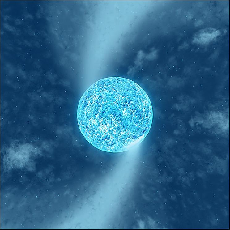
• October 25, 2017: A Canadian-led international team of astronomers recently discovered that spots on the surface of a supergiant star are driving huge spiral structures in its stellar wind (Figure 3). Their results are published in a recent edition of Monthly Notices of the Royal Astronomical Society. 7) 8)
- Massive stars are responsible for producing the heavy elements that make up all life on Earth. At the end of their lives they scatter the material into interstellar space in catastrophic explosions called supernovae - without these dramatic events, our solar system would never have formed.
- Zeta (ς) Puppis is an evolved massive star known as a 'supergiant'. It is about sixty times more massive than our sun, and seven times hotter at the surface. Massive stars are rare, and usually found in pairs called 'binary systems' or small groups known as 'multiple systems'. Zeta Puppis is special, however, because it is a single massive star, moving through space alone, at a velocity of about 60 km/s. "Imagine an object about sixty times the mass of the Sun, travelling about sixty times faster than a speeding bullet!" the investigators say. Dany Vanbeveren, professor at Vrije Universiteit Brussel, gives a possible explanation as to why the star is travelling so fast; "One theory is that Zeta Puppis has interacted with a binary or a multiple system in the past, and been thrown out into space at an incredible velocity".
- Using a network of 'nanosatellites' from the "BRIght Target Explorer" (BRITE) space mission, astronomers monitored the brightness of the surface of Zeta Puppis over a six-month period, and simultaneously monitored the behavior of its stellar wind from several ground-based professional and amateur observatories.
- Tahina Ramiaramanantsoa (PhD student at the Université de Montréal and member of the Centre de Recherche en Astrophysique du Québec; CRAQ) explains the authors' results: "The observations revealed a repeated pattern every 1.78 days, both at the surface of the star and in the stellar wind. The periodic signal turns out to reflect the rotation of the star through giant 'bright spots' tied to its surface, which are driving large-scale spiral-like structures in the wind, dubbed CIRs (Co-rotating Interaction Regions)."
- "By studying the light emitted at a specific wavelength by ionized helium from the star's wind," continued Tahina, "we clearly saw some 'S' patterns caused by arms of CIRs induced in the wind by the bright surface spots!". In addition to the 1.78-day periodicity, the research team also detected random changes on timescales of hours at the surface of Zeta Puppis, strongly correlated with the behavior of small regions of higher density in the wind known as "clumps" that travel outward from the star. "These results are very exciting because we also find evidence, for the first time, of a direct link between surface variations and wind clumping, both random in nature", comments investigating team member Anthony Moffat, emeritus professor at Université de Montréal, and Principal Investigator for the Canadian contribution to the BRITE mission.
- After several decades of puzzling over the potential link between the surface variability of very hot massive stars and their wind variability, these results are a significant breakthrough in massive star research, essentially owing to the BRITE nanosats and the large contribution by amateur astronomers. "It is really exciting to know that, even in the era of giant professional telescopes, dedicated amateur astronomers using off-the-shelf equipment in their backyard observatories can play a significant role at the forefront of science", says investigating team member Paul Luckas from the International Centre for Radio Astronomy Research (ICRAR) at the University of Western Australia. Paul is one of six amateur astronomers who intensively observed Zeta Puppis from their homes during the observing campaign, as part of the 'Southern Amateur Spectroscopy initiative'.
- The physical origins of the bright surface spots and the random brightness variations discovered in Zeta Puppis remain unknown at this point, and will be the subject of further investigations, probably requiring many more observations using space observatories, large ground-based facilities, and small telescopes alike.
• Feb. 18, 2017: Five satellites in the constellation are operational and carrying out their science mission. Different teams are responsible for the daily operations and tasking is coordinated by the BRITE Engineering and Science Team. UniBRITE and BRITE-Austria (TUGSat-1) are operated by the Technical University of Graz. BRITE-Toronto is operated by the Space Flight Laboratory at the University of Toronto. BRITE-Poland 1 (Lem) and BRITE-Poland 2 (Heweliusz) are operated by the Nicolaus Copernicus Astronomical Center. 9)
- The main website for the BRITE Constellation is provided at: http://www.brite-constellation.at/
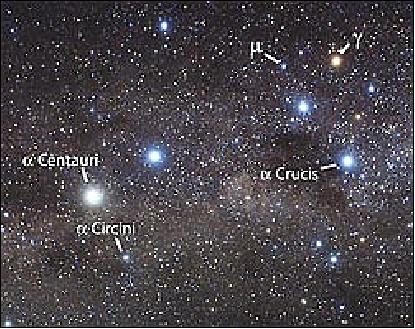
• Feb. 05, 2016: The BRITE Constellation of five nanosatellites is operational in 2016. — The constellation is revealing new information about a well-studied star, Alpha Circini. A data analysis of the BRITE Constellation Team shows a behavior in this star that has not been observed before according to Werner Weiss from the University of Vienna, Austrian Principal Investigator for BRITE and lead author of the paper. The "BRITE Constellation shows complex behavior in Alpha Cir due to both rotation and pulsation. Moreover, that behavior is different when observed in different colors. This result clearly demonstrates the power of BRITE-Constellation and the unique science that is possible using these tiny two-color precision instruments in space." 10) 11)
- The BRITE-Constellation is a coordinated mission of five nanosatellites in LEO, each hosting an optical telescope of 3 cm aperture feeding an uncooled CCD, and observing selected targets in a 24º FOV. Each nanosatellite is equipped with a single filter; three have a red filter (~ 620 nm) and two have a blue filter (central wavelength (~ 420 nm). The satellites have overlapping coverage of the target fields to provide two-color, time-resolved photometry.
- The five nanosats, each of ~7 kg, are designated as: BRITE-Austria and UniBRITE (Austria), BRITE-Lem and BRITE-Heweliusz (Poland) and BRITE-Toronto (Canada). A sixth nanosatellite, BRITE-Montreal, did not detach from its launch vehicle.
- The BRITE data are so valuable to astronomers due to their multi-colored observation. For stars, color and temperature go hand-in-hand. Having the ability to examine stars in different colors with data taken every few minutes for up to six months is providing new insights into their inner workings.
- Using these precision instruments, the BRITE-Constellation's mission is to perform a survey of the most luminous stars in the Earth's sky via a branch of astronomy called asteroseismology – literally, the study of "starquakes". Typically, massive and short-lived, these stars dominate the ecology of the Universe and are responsible for seeding the interstellar medium with the "heavy" elements critical for the formation of planetary systems and organic life. In short, BRITE studies classes of stars that, billions of years ago, made life on Earth possible.
- With an apparent magnitude of 3.19, Alpha Cir is the brightest star in the southern constellation Circinus and belongs to the class of stars known as rapidly oscillating Ap stars. The star in question was observed by four of the BRITE satellites from March to August 2014 and will be observed again in 2016. It is hoped, that these new observations will provide both a better understanding of its complex behavior and a chance to confirm a new oddity about this already peculiar star; that its speed of rotation is decelerating.
• Future of BRITE constellation (Dec. 2014:): With all BRITE satellites now in orbit and all but one commissioned, the entire constellation is expected to be fully operational by the end of the calendar year (2014). Lessons learned during the commissioning and operation of the Austrian satellites are now being applied to ensure that all satellites are commissioned quickly and then operated efficiently (Ref. 12).
- Although the BRITE-Constellation has already swollen to a size not dreamed of when it was first conceived, the mission continues to garner interest from other nations. Attracted by the enticing nature of the science, the success of the transfer programs with Austria and Poland and the relatively low-entry cost, to date, at least six other nations have expressed interest in contributing additional satellites to the constellation. In anticipation of future expansion, discussions are already underway on how those satellites can best be used to further enhance the science as the addition of BRITE-Austria did eight years before. At the top of the list is a BRITE satellite capable of observing in the ultraviolet band, an addition which would push this already highly valuable mission into even new territory.
• The first Polish BRITE, Lem, completed commissioning in July 2014 and, along with BRITE-Toronto, is currently observing the Cygnus field (Ref. 12).
• Due to the fact that UniBRITE and BRITE-Toronto are based on SFL's GNB (Generic Nanosatellite Bus), with which SFL has considerable on-orbit experience, commissioning of the core hardware complement was conducted at an accelerated pace. Within two weeks UniBRITE had commissioned everything but the payload and fine pointing hardware/algorithms. As one of the first BRITE spacecraft in orbit, a few notable hurdles were encountered and overcome before regular science operations were achieved in Sept 2013. — By the launch of BRITE-Toronto in June 2014, operations were running very smoothly and, tellingly, within eight days of the launch of BRITE-Toronto it had been fully commissioned and was collecting science data (Ref. 12).
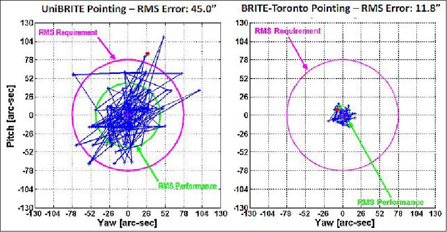
- Fine Pointing Stability and Accuracy: The performance of fine-pointing on BRITE is typically assessed using high cadence star-field images taken by the payload. Shown in Figure 5 is the motion of the centroid of a stellar PSF, over a single 15-minute observation, for both UniBRITE and BRITE-Toronto. In each plot the red circle represents the 78" requirement and the green circle the RMS error. Clearly, even for UniBRITE with the AA-MST, performance (45") is well within requirements, and quite consistent with the simulation results. BRITE-Toronto, with the ST-16 startracker, over a similar time frame is almost four times better than UniBRITE, having RMS performance of 12".
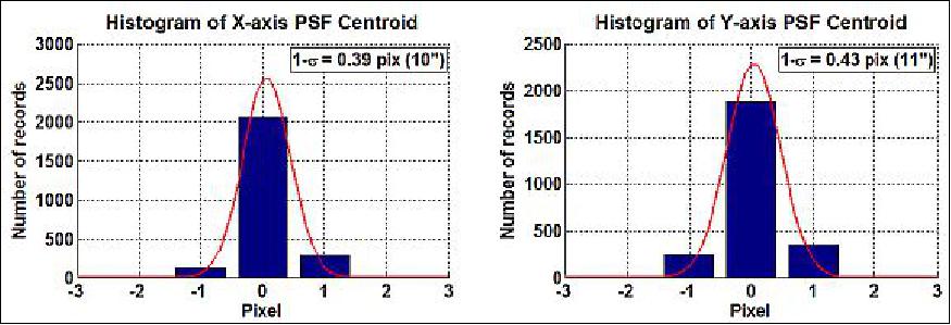
- BRITE not only needs to point stably during an observation, but also over the span of several months as the target is lost and reacquired. To assess pointing performance over a longer period, BRITE instrument scientist Rainer Kuschnig of the University of Vienna, compiled several weeks of UniBRITE and BRITE-Toronto data and found the long-term RSS values of the standard deviations in each axis to be 52" for UniBRITE and 15" for BRITE-Toronto. Hence, in both cases, from field acquisition to reacquisition, the spacecraft is able to return the stars to the same set of pixels, and the observed pointing stability is significantly better than the requirement. Figure 6 shows the X and Y axis histograms for BRITE-Toronto.
• Of the five operational spacecraft, UniBRITE and BRITE-Toronto are operated by SFL, from the Toronto Earth station. BRITE-Austria is operated by the Technical University of Graz and the Polish BRITEs are operated by the Polish Space Research Center and the Copernicus Astronomical Center.
• Unfortunately, for reasons that remain unknown, BRITE-Montreal never separated from the launch vehicle meaning the planned constellation of six satellites will only ever have five operational members. 12) 13)
• After a six and eight month commissioning period for UniBRITE and BRITE-Austria, respectively, by late 2013 both satellites were regularly observing one of the mission's primary science fields, the Orion Constellation. By March 2014 Orion had moved too close to the sun to be observed and the first observation campaign for the mission was deemed complete. From March to August 2014, the Austrian satellites observed the Centaurus field and, starting in late August 2014, began observing Perseus (Ref. 12).
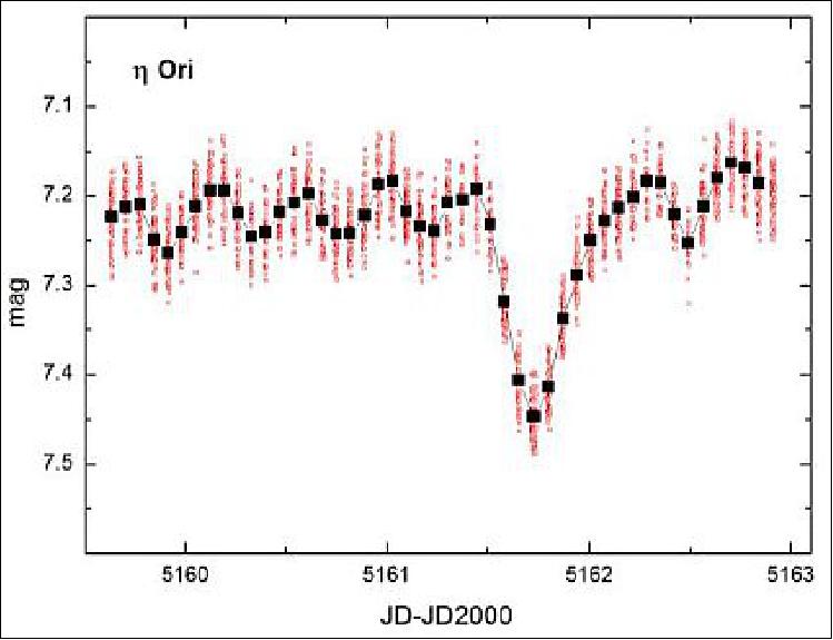
• UniBRITE commenced routine science observations of the Orion star-field in October 2013. Starting in December, BRITE-Austria joined UniBRITE on the campaign providing the mission's first two-color photometric data. Conveniently, in late 2013, MOST (Microvariability and Oscillations of STars) was also observing Eta-Orionis (a quadruple system with an eclipsing binary pair) and, for a time, all three spacecraft were performing simultaneous observations. Through the simultaneous observations with MOST, the team was able to confirm that, to first order, the quality of the BRITE data was as good as expected. A minimally post-processed light-curve of Eta-Orionis, taken by UniBRITE and with a binary transit clearly evident, is shown in Figure 7 (Ref. 12).
Sensor Complement (Photometer)
The objective is to examine the apparently brightest stars in the sky for variability using the technique of precise differential photometry in time scales of hours and more. The constellation of four nanosatellites is divided into two pairs, with each member of a pair having a different optical filter. The requirements call for observation of a region of interest by each nanosatellite in the constellation for up to 100 days or longer.
Photometer
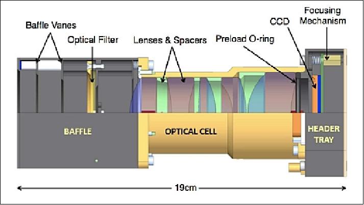
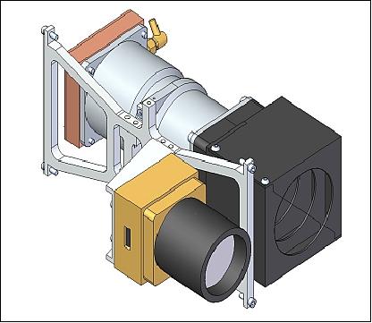
The mechanical design of the BRITE instrument (i.e., science payload) is fairly basic, which helps to ensure that maximum integration flexibility can be provided. The telescope is composed of three modules, the header electronics tray, the optical cell and the baffle. The baffle includes the aperture stop as well as the filter. The optical cell houses five lenses and the spacers that position the lenses with respect to each other.
A detailed description of the BRITE instrument design considerations regarding the optics design and focal plane is provided in Ref. 1).
The electronics tray contains the CCD header board, which includes the CCD and thermal control electronics. The associated computing and CCD driver electronics are contained separately on the IOBC (Instrument On-Board Computer), which is stacked with the other OBCs on the satellite bus to reduce payload size and limit heat dissipation within the instrument itself.
Initially, a CMOS detector was selected for its low power consumption capability. However, Fabry–Pérot fringe patterns were identified in the images taken by the prototype IBIS4-14000 CMOS imager during the early stage of the BRITE design phase. Tests performed with a uniform light source and spectrograph revealed intensity variations up to 40% across the imager at all visible wavelengths. The cause of the fringing effect was traced back to unevenness in the surface passivation layer on the CMOS imager chip. As a result the IBIS4 imager was not appropriately suited to achieve the high level of accuracy required for the scientific objective.
In the search for an alternative candidate, the BRITE team came across the STL-11000M astronomy research CCD camera assembly offered by SBIG (Santa Barbara Instrument Group). Spectrograph tests performed with this camera revealed no evidence of Fabry–Pérot fringing and intensity variation over the imager was significantly lower at approximately 6%. The result of this test steered the choice of photometer towards the Kodak KAI-11002 CCD used inside the STL-11000M SBIG camera. This CCD had relatively low power consumption and very good noise and dark current performance even at room temperature.
The science payload of each nanosatellite consists of a five-lens telescope with an aperture of 30 mm and the interline transfer progressive scan CCD detector KAI 11002-M from Kodak, along with a baffle to reduce stray light. The optical elements are housed inside the optical cell and are held in place by spacers. The photometer has a resolution of 26.52 arcsec/pixel and a field-of-view of 24º. The mechanical design for the blue and for the red instrument is nearly identical; only the dimensions of the lenses are different.
The Kodak KAI-11002 CCD is an 11M pixel interline, buried channel CCD with 4008 x 2672 effective pixel dimensions. Each pixel is 9 µm x 9 µm in size and BRITE uses the option fitted with micro lenses. At only 37.25 mm (H) by 25.7 mm (V) in size, this imager offers an impressive 66 dB dynamic range with built-in electronic shutter and anti-blooming protection.
Image size | 37.25 mm x 25.70 mm |
No of pixels | 4008 x 2672 |
Pixel size | 9.0 µm x 9.0 µm |
Peak quantum efficiency | 50% |
Full well charge (saturation signal) | 60,000 e- |
Dark current (at 20ºC) | 4 e-/s/pixel |
Power consumption | 1 W |
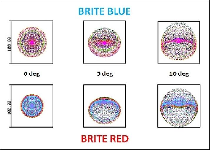
Optical design: The science team required from the PSF (Point Spread Function) to overcome undersampling issues and achieve milli-magnitude stellar photometry.
The optical designs each have an aperture of 30 mm with a focal length of 70 mm (focal ratio of 2.33). The theoretical spot diagrams for the two designs at 0º, 5º and 10º from boresight are shown in Figure 9.
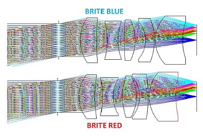
The effective wavelength range of the instrument is limited in the red by the sensitivity of the detector and in the blue by the transmission properties of the glass used for the lenses. The filters were designed such that for a star of 10,000 K (average temperature for all BRITE target stars) both filters would generate the same amount of signal on the detector. The blue filter covers a wavelength range of 390-460 nm and the red filter 550-700 nm; both are assumed to have a maximum transmission of 95%.
The photometer instrument has a mass of ≤ 0.9 kg and a power consumption of ≤ 3.5 W. The instrument uses a custom set of electronics to operate the imager. The electronics include four A/D converters (14 bit) to convert the analog pixel values, and 32 MB of memory to temporarily hold a full frame image. The imager and memory timing and signals are being controlled using a CPLD (Complex Programmable Logic Device).
CCD driver design challenges
The main challenges introduced by the shift of imaging technology were the increase in power and the complexity of the electronics required to operate the CCD. At the same time, the instrument design still had to meet the primary mission requirements including:
1) Perform differential photometry with error less than 0.1% per 15-minute observation.
2) Set exposure time between 0.1 and 100 s with an accuracy of 0.01%.
3) Achieve an integrated signal to noise ratio (S/N) of 3000 for a cumulative exposure taken over 1000 s on a V= +3.5 star.
This set of requirements can be translated into goals of providing very stable analog signal levels that operate the CCD, stable thermal control, high fidelity clocking and very low noise.
A two-board photometric CCD driver design
The performance of CCDs is extremely sensitive to temperature. Generally speaking, lower imager temperature brings higher SNR. The original STL-11000M camera assembly contains a two stage thermal electric cooling unit with liquid assist that can bring the operating temperature down to 50ºC below ambient. Unfortunately active thermal cooling is not achievable on BRITE due to volume and power constraints for the BRITE mission. These constraints drove the design towards a two-board system that would minimize the heat dissipated alongside the CCD, in the payload itself.
The first board, known as the CCD header board, contains the CCD and heater control electronics. The second board, known as the instrument on-board computer (IOBC) contains all on-board computing, power regulation and CCD driver electronics. The IOBC board is an amalgamation of a complete set of standard GNB on-board computer (OBC) and the entire driver electronics required to operate the CCD imager. Only the driver design aspects will be discussed.
The two-board configuration not only mitigates thermal issues, it also isolates the imager from the noise generated by supporting electronics located on the IOBC. The tradeoff made here is the increased distance that the data, in analog form, must travel in order to arrive at the ADC (Analog-to-Digital Converter). In order to safe guard against signal depreciation, an amplifier unit was placed on the CCD header board and a coaxial cable is used for signal transfer. These two implementations help preserve the high SNR achievable by the CCD.
CCD thermal control
Perhaps one of the largest challenges in CCD-based astronomical missions is thermal control of the imager itself. CCD detectors are susceptible to two main detrimental effects: noise, and dark current. Both can significantly reduce the detector's ability to image faint stars, and great measures are taken to reduce these effects by lowering the CCD temperature, sometimes to as low as -110ºC.
Due to the small size, extremely limited power and full sky coverage requirement of the BRITE satellite, neither active nor passive (radiative) cooling schemes were feasible. Fortunately, since BRITE will image only the very brightest objects in the sky and because the chosen CCD has relatively low noise, even at room temperature, reducing the absolute temperature of the detector is a secondary concern. Of higher importance is the thermal stability of the CCD over the course of an observation window. Since an observation consists of a number of co-added exposures, it is essential that all exposures be taken with the detector at the same temperature. The BRITE requirements state that temperature of the CCD must be stable to ±2.5ºC throughout an observation, with a goal of ±0.5ºC.
As controlled cooling of the BRITE instrument is not practical, thermal stability is achieved by way of heating, which is much simpler to implement. Located towards the center of the spacecraft, the thermal fluctuations of the instrument are significantly lower than those of components located closer to the surfaces. Trim heaters are used to bring the CCD temperature to just above the highest temperature it normally experiences during the orbital cycle. Figure 12 shows a theoretical uncontrolled CCD temperature fluctuation throughout the orbit, as well as the temperature stabilized with heaters.
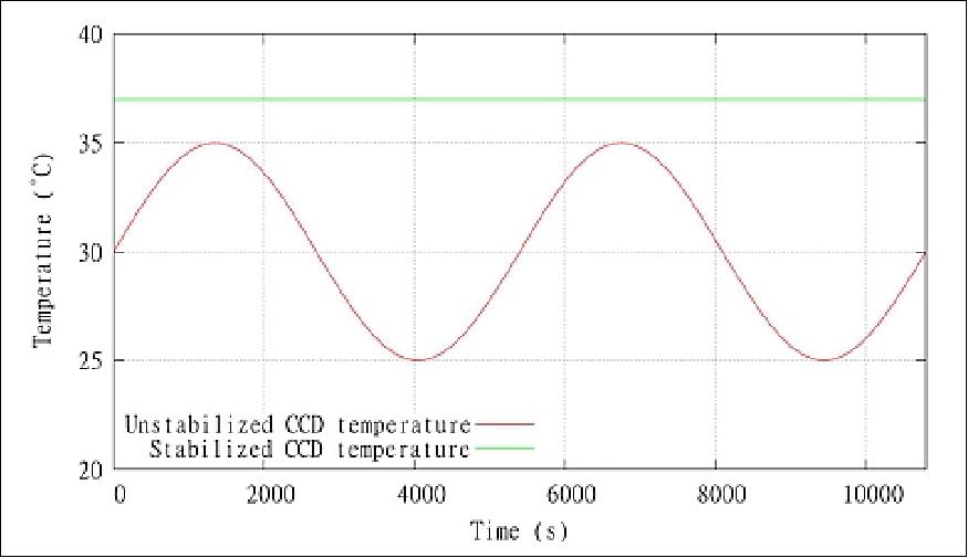
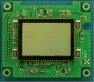
Figure 13 shows the CCD mounted to the header board with four resistive heaters placed near the corners of the CCD. Four temperature sensors are located underneath the CCD and are coupled to it with a thermal gasket. A microcontroller is located on the opposite side of the header board. The microcontroller collects temperatures from the four temperature sensors, controls power to the heaters, and communicates with the IOBC.
As the heaters are resistive, the heat produced is basically equal to the power dissipated. This suggests that the power output of the heaters can be controlled by either varying the voltage across it, or the current through it. However, analog circuitry to accomplish such control would add complexity and increase the part count. Instead, it was decided to use a PWM (Pulse-Width-Modulation) scheme, in which the heater is either fully on or fully off, with a variable duty cycle. The duty cycle would then correspond to the average power produced by the heaters.
A PID (Proportional-Integral-Derivative) controller was selected to control the PWM duty cycle of the heaters. This scheme was selected due to its simplicity and ubiquity in digital control applications. A PID controller is also very intuitive to tune, and does not require substantial computational resources to execute.
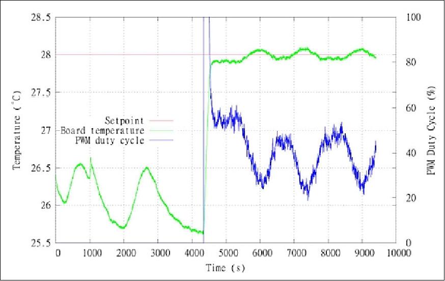
Bench-top tests conducted at room temperature and atmospheric pressure have shown that the controller can achieve a control accuracy of ±0.1ºC, which is 25 times better than the required control accuracy. Figure 14 shows these results. The green line represents the average CCD header temperature. The time interval from 0 to 4200 s shows an uncontrolled state, with temperature fluctuations due to changes in ambient temperature. Once turned on at 4200 s, the controller quickly achieves the target of 28ºC and successfully maintains it for the remainder of the test. The blue line represents the duty cycle of the PWM signal applied to the heaters. Due to the naturally slow response time of the system, it was found that a mostly proportional controller can achieve good results. Comparable performance was achieved while performing thermal vacuum testing on the integrated spacecraft, whereby the spacecraft was subjected to the thermal oscillations expected in orbit.
Mission Operations Concept and Software
The main objective of each satellite in the BRITE constellation is to observe the brightest stars in the sky and measure variability in their brightness over time. As target fields can be anywhere in the sky and there will be times during which the target fields will be obstructed by the Earth, the sun, or he moon, a minimum 15 minute interval of view of the target is expected for each orbit. This window will henceforth be referred to as the observation window. During an observation window the satellite will point at its target and perform as many observations as possible. An observation consists of a number of individual exposures which are co-added together to produce a single data point on the brightness curve.
To enable differential photometry, target fields will be selected such that more than one star of interest falls into the FOV (Field of View) of the instrument. The region around a star of interest is called a raster, and up to 16 rasters could be imaged during any given observation. To accommodate the satellite's limited downlink capacity, most of the data processing will occur onboard the satellite, with only minimal information being stored and forwarded to the ground. Full or even partial images will be downloaded only for commissioning and debugging purposes. All data sent to the ground will be compressed on-board first.
To accommodate the observation plan described above, an operational concept was developed and a high-level operations cycle defined for each of the satellites in the BRITE constellation. This concept was then flowed down to define the required ground and flight software. The top-level operational cycle is shown in Figure 15. 14)
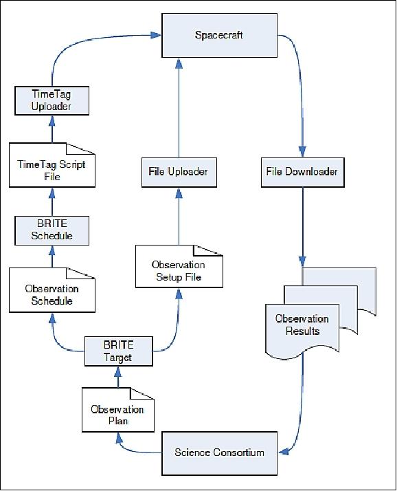
The operational cycle begins with the science consortium, which consists of 12 lead scientists and investigators for the mission. The science consortium collects observation requests from the astronomy community, selects targets and times for observations and releases this information through the observation plan. The observation plan is entered into the BRITE Target ground application, which takes into account the time of year, positions of stars in the sky, and the orbit of the satellite to determine feasible observation times as well as the required spacecraft attitude. The BRITE Target produces two files: an Observation Setup File that is uploaded directly onto the satellite's instrument computer, as well as an Observation Schedule File that is passed to the BRITE Schedule ground application.
The Observation Schedule File contains the times at which the target will be visible to the satellite, and the attitude to which the instrument must point. BRITE Schedule converts this information into a series of timed commands in a format understandable by the spacecraft. It also adds other commands that are necessary to initiate an observation. BRITE Schedule outputs these commands to a TimeTag Script file, which is then uploaded to the housekeeping computer on the spacecraft through the TimeTag ground application.
The Observation Setup File contains instructions for the instrument computer that specify the number and duration of exposures to be taken for each observation, the location of the targets in the imager's field of view, and the type of processing that must be done on the raw data.
At the time specified by the TimeTag commands, the satellite's housekeeping computer turns on the instrument computer, performs initialization routines, and begins the observation. Observations continue until the time at which the target is no longer visible, is polluted by stray light or fine pointing lock is lost, at which point the instrument computer is shut down.
During every pass over the ground station observation results are downloaded through a File Downloader application. The observation results are then returned to the science consortium for processing, concluding the observation cycle.
Spacecraft-level operations sequence
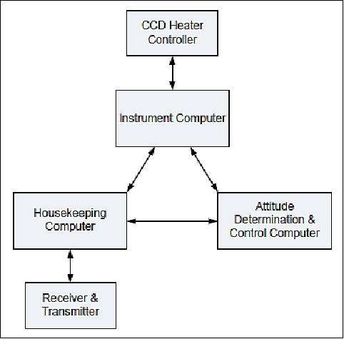
Each BRITE satellite is designed around SFL's GNB (Generic Nanosatellite Bus). Each BRITE satellite contains three onboard computers: the HKC (Housekeeping Computer), the ADCC (Attitude Determination and Control Computer), and the IOBC (Instrument On-Board Computer). Additionally, a dedicated microcontroller is responsible for the thermal control of the CCD. In nominal operations, the HKC receives all ground commands and distributes them to the appropriate destinations on the spacecraft. Likewise, all outgoing traffic is forwarded to the ground through the HKC. Since the CCD heater controller is connected only to the IOBC, all commands to it must be forwarded by the IOBC. Figure 16 shows a simplified interconnect diagram for the onboard computers.
The HKC houses the TimeTag command interpreter. Each entry in the TimeTag queue contains a command as well as the time at which it should be executed. When the command time elapses, the HKC forwards the command to the appropriate computer for processing. TimeTag provides a necessary means of automation as observations will most often occur outside of contact periods with the ground.
During a ground pass, a TimeTag Command File and an Observation Setup File are uploaded to the HKC and IOBC respectively. At a predetermined time before the observation is scheduled to begin, the HKC begins configuring all of the satellite subsystems. First, the attitude determination and control system is enabled and sensors are given a warm-up period. If necessary, a slew is performed to point the instrument at the target. Following the slew, commands are issued to the power distribution module directing it to turn on the instrument, IOBC, and CCD thermal control subsystem. The CCD heater controller is enabled and allowed to settle to the desired temperature. With the satellite pointing in the right direction and the CCD thermally stable, the instrument is configured and the observation cycle initiated.
Observations continue autonomously until the HKC issues a time-tagged command to halt observations. While in an exposure, the IOBC continuously polls telemetry from the ADCC and CCD Heater Controller to ensure that the spacecraft attitude and CCD temperatures are within an acceptable range for imaging. Once observations are finalized, to conserve power the power distribution module is commanded to power down all instrument electronics and the satellite returns to its pre-observation state. This cycle is repeated once per orbit until new targets are selected and new observation scripts are uploaded.
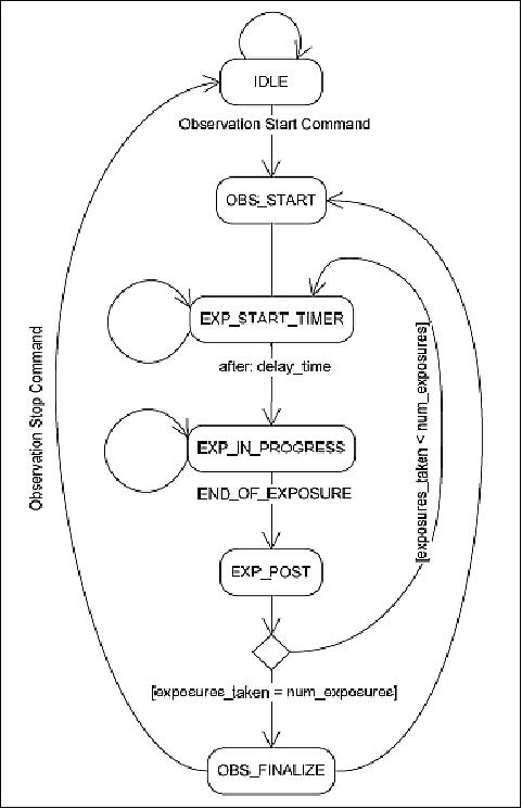
Instrument computer operations sequence
Once an observation start command is received by the IOBC, it begins an autonomous cycle of observations with the parameters defined in the observation setup file. An observation window spans the time between an observation start command and an observation stop command. It may consist of multiple observations, and each observation may be composed of multiple co-added exposures. The number of exposures, the locations and sizes of rasters within the FOV, and the type of processing to be performed on them are all defined within the observation setup file. Figure 17 shows the state transitions occurring on the instrument computer during an observation window.
References
1) Jake C.T. Cheng, Jakob Lifshits, C. Cordell Grant, Mihail Barbu, Robert E. Zee, "The BRITE Constellation Space Telescope Design and Test of a Wide Field, High Resolution, Low Noise Optical Telescope for a Nanosatellite Constellation," Proceedings of the 25th Annual AIAA/USU Conference on Small Satellites, Logan, UT, USA, Aug. 8-11, 2011, paper, SSC11-I-1
2) B. Johnston-Lemke, K. Sarda, C. C. Grant, R. E. Zee, "Arc-Minute Attitude Stability on a Nanosatellite: Enabling Stellar Photometry on the Smallest Scale," Proceedings of the 25th Annual AIAA/USU Conference on Small Satellites, Logan, UT, USA, Aug. 8-11, 2011, paper: SSC11-X-7
3) Patrick Blau, "Dnepr Rocket successfully Launches Cluster of 37 Satellites," Spaceflight 101, June 19, 2014, URL: http://www.spaceflight101.com/dnepr-launch-updates---2014-cluster-launch.html
4) William Graham, "Russian Dnepr rocket lofts record haul of 37 satellites," NASA Spaceflight.com, June 19, 2014, URL: http://www.nasaspaceflight.com/2014/06/russian-dnepr-rocket-record-launch-37-satellites/
6) Patrick Blau, "Dnepr - 2014 Cluster Launch," Spaceflight 101, June 10, 2014, URL: http://www.spaceflight101.com/dnepr-launch-updates---2014-cluster-launch.html
7) "Spots on Supergiant Star Drive Spirals in Stellar Wind," Royal Astronomical Society, 25 Oct. 2017, URL: https://www.ras.org.uk/news-and-press/3058-spots-on-supergiant-star-drive-spirals-in-stellar-wind
8) Tahina Ramiaramanantsoa, Anthony F. J. Moffat, Robert Harmon, Richard Ignace, Nicole St-Louis, Dany Vanbeveren, Tomer Shenar, Herbert Pablo, Noel D. Richardson, Ian D. Howarth, Ian R. Stevens, Caroline Piaulet, Lucas St-Jean, Thomas Eversberg, Andrzej Pigulski , Adam Popowicz, Rainer Kuschnig ,Elżbieta Zocłońska, Bram Buysschaert, Gerald Handler, Werner W. Weiss, Gregg A. Wade, Slavek M. Rucinski ,Konstanze Zwintz, Paul Luckas, Bernard Heathcote, Paulo Cacella, Jonathan Powles, Malcolm Locke, Terry Bohlsen, André-Nicolas Chené, Brent Miszalski, Wayne L. Waldron, Marissa M. Kotze, Enrico J. Kotze, Torsten Böhm, "BRITE-Constellation high-precision time-dependent photometry of the early-O-type supergiant Zeta Puppis unveils the photospheric drivers of its small- and large-scale wind structures," Monthly Notices of the Royal Astronomical Society (MNRAS), stx2671, https://doi.org/10.1093/mnras/stx2671, Published: 13 October 2017
9) Information provided by Daniel D. Kekez, Senior Missions Engineer at UTIAS/SFL.
10) "BRITE-Constellation Sees Stars in a New Light," UTIAS/SFL, Feb. 5, 2016, URL:
http://utias-sfl.net/?p=2391
11) W. W. Weiss, H.-E. Fröhlich, A. Pigulski, A. Popowicz, D. Huber, R. Kuschnig, A. F. J.Moffat, J. M. Matthews, H. Saio, A. Schwarzenberg-Czerny, C. C. Grant, O. Koudelka, T. Lüftinger, S. M. Rucinski, G. A. Wade, J. Alves, M. Guedel, G. Handler, St. Mochnacki, P. Orleanski, B. Pablo, A. Pamyatnykh, T. Ramiaramanantsoa, J. Rowe, G. Whittaker, T. Zawistowski, E. Zocłonska, K. Zwintz, "The roAp star α Circini as seen by BRITE-Constellation," Astronomy & Astrophysics manuscript No. alCirArchiv (@ESO 2016), January 20, 2016, URL: http://arxiv.org/pdf/1601.04833v1.pdf
12) C. Cordell Grant, Karan Sarda, Monica Chaumont, Robert E. Zee, "On-Orbit Performance of the BRITE Nanosatellite Astronomy Constellation," Proceedings of the 65th International Astronautical Congress (IAC 2014), Toronto, Canada, Sept. 29-Oct. 3, 2014, paper: IAC-14-B4.2.3
13) Karan Sarda, C. C. Grant, M. Chaumont, S. Choi, B. Johnston-Lemke, R. E. Zee, "On-Orbit Performance of the BRIghtTarget Explorer (BRITE)NanosatelliteAstronomy Constellation," Proceedings of the AIAA/USU Conference on Small Satellites, Logan, Utah, USA, August 2-7, 2014, paper: SSC14-XII-6, URL: http://digitalcommons.usu.edu/cgi/viewcontent.cgi?article=3077&context=smallsat
14) Jacob Lifshits, Robert E. Zee, "Embedded Systems Development for SFL Satellites," MASc Thesis, Graduate Department of Aerospace Science and Engineering, University of Toronto, Toronto, Canada, 2010, URL:
https://tspace.library.utoronto.ca/bitstream/1807/25764/1/Lifshits_Jakob_201011_MASc_thesis.pdf
The information compiled and edited in this article was provided by Herbert J. Kramer from his documentation of: "Observation of the Earth and Its Environment: Survey of Missions and Sensors" (Springer Verlag) as well as many other sources after the publication of the 4th edition in 2002. - Comments and corrections to this article are always welcome for further updates (eoportal@symbios.space).
Spacecraft Launch Mission Status Sensor Complement Concept and Software References
Back to top