CanX-6 (Canadian Advanced Nanosatellite eXperiment-6) / NTS
Non-EO
Mission complete
CSA
Technology and Research
Quick facts
Overview
| Mission type | Non-EO |
| Agency | CSA |
| Mission status | Mission complete |
| Launch date | 28 Apr 2008 |
| End of life date | 31 Dec 2015 |
CanX-6 (Canadian Advanced Nanosatellite eXperiment-6) / NTS
Spacecraft Mission Status Experiments References
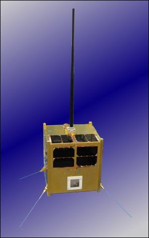
CanX-6 is a follow-up nanosatellite demonstration mission of UTIAS/SFL (University of Toronto, Institute for Aerospace Studies/Space Flight Laboratory), Toronto, Canada. The CanX-6 project was started in October 2007 as a collaboration between COM DEV International Ltd. of Cambridge, Ontario, Canada and UTIAS/SFL to develop a nanosatellite that will serve to demonstrate key elements of the COM DEV spaceborne AIS (Automatic Identification System) detection technology and enable any design changes to be incorporated prior to launching full operational systems. Due to these objectives, the spacecraft is also known as NTS (Nanosatellite Tracking Ships). In fact, COM DEV commissioned UTIAS/SFL to build the experimental spacecraft, integrate the COM DEV payload, and to operate the spacecraft. 1) 2) 3)
Spacecraft
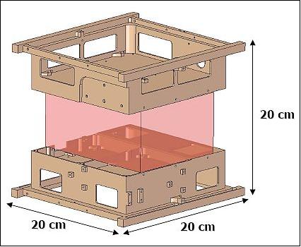
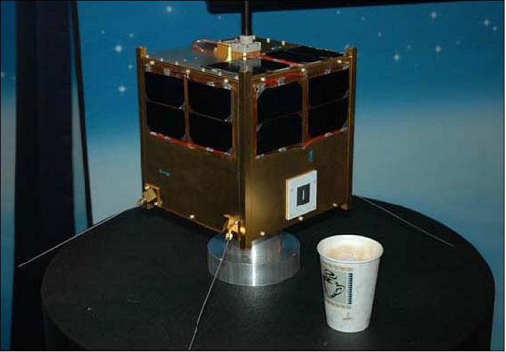
The bus for CanX-6 is provided by UTIAS/SFL. It is a combination of CanX-2-class electronics mounted onto the 200 x 200 x 200 mm structure developed for the Generic Nanosatellite Bus (GNB) used also by the upcoming BRITE, and CanX-4 &5 missions. The CanX-6/NTS mission represents in fact the first realization and flight of the newly developed modular GNB platform of UTIAS/SFL, a cube with a form factor of 20 cm side length. 4) 5)
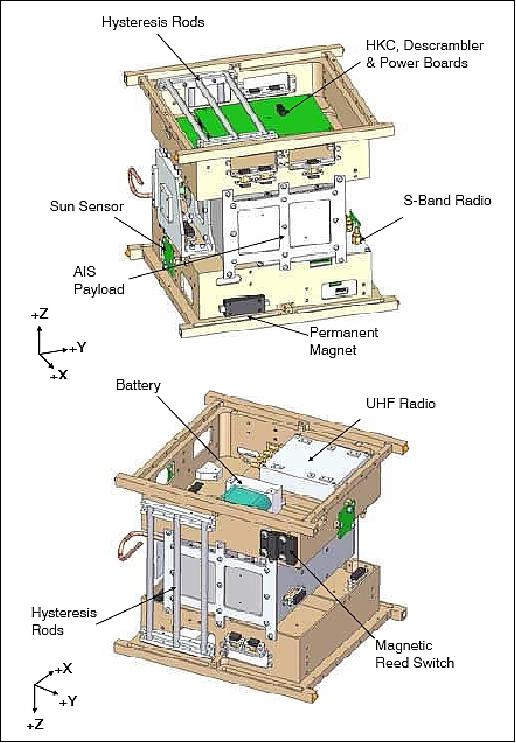
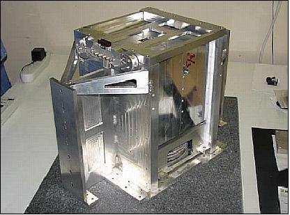
The GNB structure (using Al 6061-T6 aluminum) consists of two trays and six external panels. A dual tray structure was selected to maximize the payload bay and to provide ease of integration (Figure 2). The trays and panels can be manufactured from either aluminum or magnesium alloys, depending on the mass requirements of the mission. The two trays contain all the necessary components for a basic satellite mission, including communications, attitude determination and control, power and thermal/structural components.
A typical GNB consists of one ARM7 housekeeping computer as well as two ARM7 computers for attitude control and payload operations, respectively. The GNB incorporates a direct energy-transfer power system utilizing up to six triple-junction solar cells on each face and battery storage to supply 8 W peak and 5.6 W nominal for the satellite. The Li-ion battery has a capacity of 5.3 Ah. CanX-6 / NTS has a spacecraft mass of 6.5 kg.
The GNB platform is stabilized using passive magnetic attitude control. Control is provided through a permanent magnet aligned with the axis of the payload antenna. This provides ±20º positioning about the magnetic field vector. Damping is provide by two hysteresis rods. The roll axis is not controlled.
The payload and antenna were developed by COM DEV, and spacecraft integration took place at UTIAS/SFL.
Spacecraft mass, size | 6.5 kg, 20 cm x 20 cm x 20 cm (GNB structure) |
Power | 8 W max, |
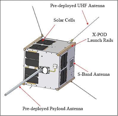
Stabilization | Passive: use of permanent magnet and 6 hysteresis rods (and boom) to maintain the alignment of the AIS VHF monopole antenna to the local magnetic field lines |
On-board memory | 16 MByte in the HKC; 16 MByte (TMR) in the payload |
Launch
A shared launch of CanX-6/NTS as a secondary payload took place on April 28, 2008. The PSLV launch vehicle (PSLV-C9) of ISRO carried ten spacecraft into orbit from the SDSC-SHAR launch site (Sriharikota, India) of ISRO. The primary payload on this flight was CartoSat-2A (launch mass of 690 kg), an Indian military high-resolution panchromatic imaging satellite (based on CartoSat-2 of ISRO). 6)
The other secondary payloads on the flight were 1 microsatellite and 7 nanosatellites: IMS-1 of ISRO (a microsatellite of 83 kg, formerly called TWSat); CanX-2 of UTIAS/SFL, Toronto, Canada; AAUSat-2 of Aalborg University, Denmark; COMPASS-1, University of Applied Science, Aachen, Germany; Delfi-C3 of the Technical University of Delft, The Netherlands; SEEDS-2 of Nihon University, Japan; CUTE-1.7+APD-2 of of the Tokyo Institute of Technology, Japan; and Rubin-8-AIS (7 kg) an experimental space technology mission of OHB-System, Bremen, Germany. 7)
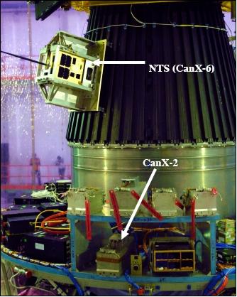
CanX-6 was deployed using the XPOD (Experimental Push Out Deployer) GNB separation system of UTIAS/SFL. The customizable system is capable of deploying small payloads of size 20 cm x 20 cm x 40 cm (max) with a mass of 14 kg (max).
Orbit: Sun-synchronous orbit, altitude = 635 km, inclination = 98º, period = 97.4 minutes.
RF communications: UHF-band uplink (4 kbit/s) and downlink, and an S-band downlink (GMSK modulation, AX.25 protocol) with data rates between 32 kbit/s and up to 1 Mbit/s (max). Use of 4 quad-canted monopole antennas.
Spacecraft operations: The CanX-6 / NTS nanosatellite is being operated by the mission control center at UTIAS/SFL.
The commercial contract of COM DEV represented for UTIAS/SFL an excellent opportunity to provide a quick response solution to the needs of a customer (~1/2 year from contract to launch).
Mission Status
• 2015: The NTS nanosatellite was launched in April 2008 with the goal of demonstrating the reception of AIS signals from space. The satellite was built in partnership with UTIAS/SFL. 8)
- As a technology demonstration, the CanX-6/NTS satellite and mission needed to survive a minimum of 1 month in order to demonstrate its objectives; however, it was hoped that the mission would last as long as 6 months to characterise the RF environment. The mission easily met its requirements and became an operational part of the fledgling exactEarth constellation. NTS was even used operationally to provide data for the World Cup in South Africa and the Olympic Games in Vancouver, Canada. As of April 2015, the NTS satellite is no longer part of the operational AIS constellation of satellites but is still used as an experimental platform to test out the latest innovations in spaceborne AIS detection.
• The CanX-6/NTS spacecraft is operating nominally in 2012. 9)
• The CanX-6/NTS spacecraft is operating nominally in January 2010. At this time, the spacecraft operated already for 1 year and 9 months in orbit and continues to operate nominally in its extended mission phase.. The original target lifetime was 1 month. The satellite met all mission requirements and programmatic targets. 10) 11)
- Extended operations: a) Upgraded spacecraft software with scheduling capability, and b) Automated data downlink and distribution .
- Continues to collect AIS data: a) 16 MB per day best case into one station (2.1 m dish), b) Targeting 30 MB per day into one station with additional protocol improvement.
- Collaboration with DRDC ground station: a) for data-intensive, low-latency operations; b) demonstrated SFL rapid deploy ground station network; c) currently with 6 stations across North America and Europe.
• During normal operations, observation schedule is uploaded to the spacecraft. At the pre-calculated position in orbit, the spacecraft will begin collecting AIS data from specific surface area of interest. 12)
In addition to the SFL primary ground station in Toronto, two additional ground stations are now online. A 9.1 m dish at the Defense Research and Development Canada (DRDC) in Ottawa is now available for use with SFL nanosatellites. This dish is now part of the SFL network of ground stations and is being remotely operated from the SFL mission control center in Toronto. The addition of this dish further enhances the data throughput from the spacecraft by permitting downlink at the highest data rate available over the entire pass. The third ground station is currently being commissioned jointly by COM DEV and SFL, and will be dedicated to NTS operations (Ref. 12).
• April 2009: After one year in orbit, the spacecraft is functioning nominally (the mission was originally targeted for one month of operation). The operation of the CanX-6 / NTS nanosatellite is considered a complete success - namely to demonstrate the AIS technology for the follow-up M3MSat (Maritime Monitoring and Messaging Microsatellite) microsatellite mission, currently under development in Canada at COM DEV Ltd. 13) 14) 15)
• May 6, 2008: Collection of first set of AIS data.
• May 2, 2008: Start of payload commissioning
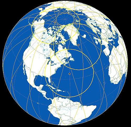
• Footprint overlap between CanX-2 and NTS (CanX-6) during the first month.
• Press release: On June 5, 2008, COM DEV announced in a press release that a spaceborne AIS payload, launched on a dedicated satellite on April 28, has validated the advanced spaceborne AIS performance capability which COM DEV has developed. The system is providing comprehensive advanced AIS data which enables a level of global vessel detection that is not achievable by any other known spaceborne system. The trial has validated COM DEV's predicted performance levels over large coverage areas. The data collected is also being used to validate vessel traffic densities and to characterize any potential interference sources. This data will enable the design and development of an optimized system for global coverage. 16)
• Due to memory constraints onboard the HKC (House Keeping Computer), the payload is only commanded to operate for a maximum of 90 seconds at a time. A full 90 seconds of data takes 3-5 days to download over the S-band link at UTIAS/SFL. In order to facilitate a faster download of data a secondary ground station is being constructed at the University of Aalborg in Denmark. 17)
Operations of the NTS satellite payload are performed using two basic modes, full recording and partial recording. When using the full recording mode the payload is powered on, configured and the data recorder turned on. Recording continues until the payload memory has been completely filled, at which point the HKC will start requesting the data for transmission to the ground. The partial recording mode provides the ability to perform small bursts of recording over several different areas of the globe. In this mode a series of areas of interest (AOI) can be generated during a single orbit.
Experiment Complement (NTS payload)
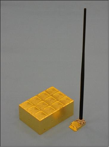
The NTS payload is a self-organizing radio communication system used for the identification and location of maritime vessels. The AIS assembly, receiver and antenna, was developed by COM DEV Ltd. The overall objective is proof-of-concept and the provision of the instrument performance characteristics (Ref. 5).
The NTS radio is designed to perform AIS signal receive, store and forward functions covering the two AIS frequencies of 161.975 and 162.025 MHz. The payload supports commandable channel frequencies and covers the channel bandwidths with margins for Doppler shift.
The RF front-end filter module receives signals from the monopole antenna. With the large coverage area of the antenna, various interference sources under the antenna footprint will be picked up in addition to the AIS signals of interest. Therefore, a high-performance front-end filter, developed by COM DEV, is used in the NTS payload to provide attenuation of the interference outside of the AIS bands while maintaining very low insertion losses for the AIS signals.
The RF module of the NTS payload takes classic receiver approaches and adopted standard IF frequencies to permit using low cost COTS components for the implementation. The received RF signal splits after a low noise amplifier (LNA) to feed the two AIS RF modules. The double channel implementation minimizes the burden on the DSP (Digital Signal Processing) section of the payload and provides redundancy for the AIS RF module section.
The digital module of the payload includes analog/digital (A/D) conversion and digital processor sections. The A/D conversion samples the AIS signal at IF frequencies and feeds the samples to the digital processor. Anti-alias filters are used before the A/D converters to minimize the impact of interference beyond the sampling frequency to fold back into the signal band.
The digital back-end contains the digitization, power control, further filtering and all the command handling and telemetry generation for the payload. The field programmable gate array (FPGA) is expected to acquire the digital data from the two channels, digitally downconvert it and remove in-band noise. The data is compressed, packetized and encrypted, then buffered into on-board static random access memory (SRAM) that is sized to the capability of the bus. On request, the data is transmitted to the housekeeping computer via dedicated data interfaces.
The payload commandability is fairly extensive for its size, with independent control of each AIS channel, including at the level of receiver tuning, filter control, gain settings etc, with telemetry status for each command, recording depth and memory and logic errors. In addition, a signal statistics function exists, allowing the payload to collect average received signal strength data in parallel to, or instead of, captured signal. This mode supports a spectrum survey capability for identifying optimal global gain settings and for identifying locations with a potentially higher-than-average noise floor.
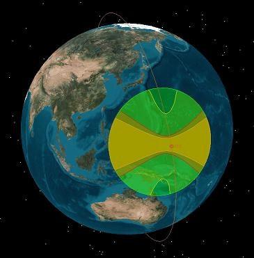
The footprint of the AIS antenna is about 5,000 km from an orbital altitude of 620 km. Figure 8 illustrates the footprint over the equator, the colors/profile illustrating the different gain contours of the antenna.
An AIS System Performance Discussion
This chapter involves a paper by Ian D'Souza and David Martin of COM DEV and exactEarth. The text of their views is presented almost in its entirety. The content might be of general interest to the AIS reader community. 18)
Terrestrial AIS concept
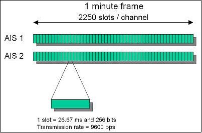
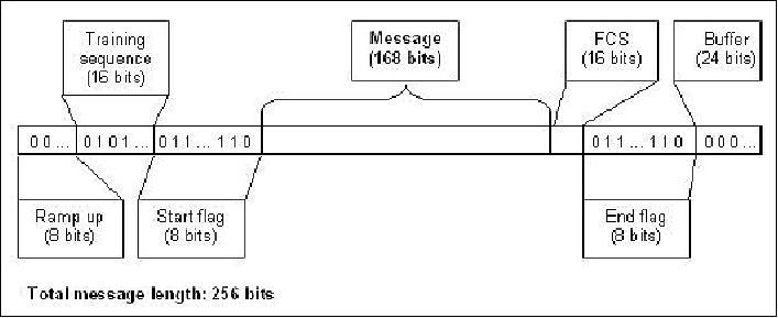
Terrestrial AIS is a signalling system between ships and ships and shore-stations that uses two VHF narrow band (25 kHz) channels at 161.975 MHz and 162.025 MHz. The signal transmitted is a GMSK (Gaussian Minimum Shift Keying) modulated carrier and the use of a SOTDMA (Self-Organized Time Division Multiple Access) protocol. The protocol makes use of short time slots that partition a one-minute ‘frame' that allows for up to 4500 time slots per frame to be sent. Figure 11 shows a schematic of the time division of the two AIS channels, each with 2250 slots of 26.7 ms each. Figure 12 shows the makeup of messages transmitted in a single slot.
Ships alternatively transmit on AIS channel 1 and 2, and the TDMA protocol ensures that no signal transmissions ‘collide' for the local ‘cell' of ships. In theory, a large number of ships can be accommodated using this scheme without congestion. The signal transmission range is typically about 50 nautical miles and this characterizes the size of a cell of ships that are self-organized.
Ships at distances greater than 50 NM from other ships need not be coordinated using this TDMA protocol, because the time slots can be re-used due to low signal strength from far away ships. Typical information transmitted on AIS channels includes the ship's identification, latitude, longitude, speed, heading, course over ground, rate of turn etc. Certain AIS messages include other information such as destination, crew information or cargo. The AIS standard calls up to 26 different AIS message types that contain varied information.
The following parameters listed summarize/characterize AIS signals as transmitted and received on the surface of the Earth:
- Centre Frequency: 161.975 MHz (AIS channel 1), 162.025 MHz (AIS channel 2)
- Bandwidth: 25 kHz per channel
- Power: 12.5 W (Class A), 2.5 W (Class B)
- Transmission Range: 50 nautical miles radius (i.e. to the horizon)
- Modulation: Frequency modulation, GMSK at 9.6 kbit/s
- TDMA Frame and Slot: 1 minute frame timing extracted from GPS signals, 26.7 ms slot (256 bit)
- Typical Antenna Mounting: Vertically polarized monopole or dipole antenna mounted at some height above the ship's deck, typically to a mast.
- Propagating Energy of Transmission: Primarily line of sight and along the surface of the Earth (i.e. perpendicular to the antenna).
- Carrier to Co-channel Interference Ratio Threshold C/I : 10 dB
- Typical Maritime AIS Receiver Sensitivity: -108 dBm for 20% packet error rate.
As can be seen from the signal propagation characteristics and ship antenna mounting, because AIS was designed to be a terrestrial system, the radiated energy from the mast-mounted shipboard antennas will propagate primarily along the surface of the Earth to other ships and shore stations and not upwards towards satellites in Earth orbit.
Space-based AIS
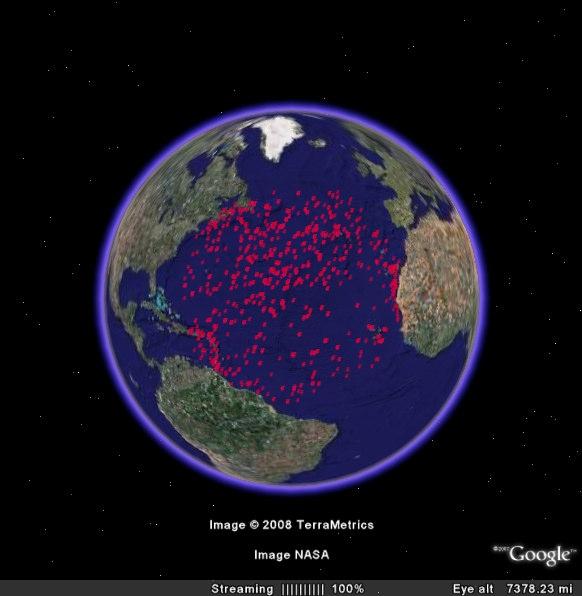
By receiving AIS messages (designed for terrestrial transmissions) in orbit, a wide-area maritime surveillance would be possible. Even a single satellite receiving AIS could eventually map the world's shipping traffic over time, obtaining new statistical knowledge of the world's shipping traffic as clearly demonstrated by COM DEV's NTS mission, which has been in operation for two years.
However, while the demonstration of the utility of AIS has proceeded quite quickly and smoothly, with AIS being used for maritime traffic awareness, collision avoidance and vessel traffic management, the terrestrial AIS network was never designed for signal reception from earth orbit. This has posed some interesting challenges. Any space based AIS receiving system will have some degree of latency due to the orbits of satellites and locations of ground stations at which satellites download the received data. Thus, AIS signals received in orbit are never intended to provide realtime navigational information, but they are still able to provide excellent situational awareness. A LEO satellite will fly over any given area in a time measured in minutes, thus continued monitoring of any particular area is also not possible. These effects must not be seen as short-comings of the system, because as few as 6 satellites can cover every area of the globe with refresh rates of 2 hours typically (in equatorial regions), and much lower rates at the higher latitudes.
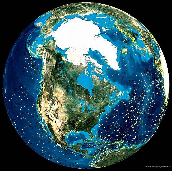
An additional complication arises because the self-organized nature of the TDMA signals between ships is lost when viewed from the vantage point of LEO (Low Earth Orbit). The very large IFOV (Instantaneous Field of View) of the satellite allows signals from a vast array of SOTDMA (Self-Organized Time Division Multiple Access) ‘cells' to be received at the satellite receiver, Figure 14.
Hence, the AIS signals that arrive at the satellite consist of multiply collided (overlapped) TDMA time slots from multiple cells. The problem that is faced by space-based AIS systems is how to deal with these overlapping AIS signals. Solution possibilities include narrowing the field of view (requires very large antenna arrays), waiting for statistically random signal messages that do not have overlaps (long observation time required) or attempting to unravel the overlapping messages (difficult algorithms).
The NTS (Nanosatellite Tracking Ships) AIS receiver experiment relies on sophisticated algorithms that attempt to unravel the overlapping messages.
Spaceborne AIS Receiver Performance
The reception of AIS signals transmitted by the 12.5 watt class A type transponders on board sea going vessels and from shore base stations has been demonstrated by several companies as well as the US government's TacSat-2 mission (launch Dec. 16, 2006). That AIS signals might be detected from LEO and thus be used for a more global awareness of ship movement was postulated years ago (post September 11 2001), by the US Coast Guard, with initial speculation of the possibility dated back perhaps 10 years.
In the years since, a few companies and institutions have launched some type of AIS receivers into LEO, including the NRL (Naval Research Laboratory), Orbcomm, SpaceQuest, LuxSpace and COM DEV. It is expected that very soon some European AIS receivers and satellites may be tested. To date, some comparisons have been made between these assets officially and un-officially. COM DEV maintains that the NTS AIS receiver out-performs all other known space AIS assets.
Measure of performance
Several metrics have been considered to characterize the performance of a spaceborne AIS receiver. One may try to determine some fraction of Class A AIS transmitting ships that are detected. This procedure is fraught with difficulties primarily because no ground truth exists for the actual number of ships transmitting AIS signals in any particular location, especially ships far out in the oceans, away from ground-based receivers. - It is proposed here that a better comparison metric is the number of ships detected per unit time, or the number of AIS messages detected per unit time of observation. The messages/unit time counted in this should be the number of verified (frame check verified) messages only, not partial or potential messages.
The global average rate of detection of the NTS nanosatellite is about 15 messages/s. The detection rate can peak at about 35 messages/s in certain areas such as the Atlantic. As the following Table 2 shows, the message rate of (1) a standard terrestrial AIS receiver launched into orbit, or (2) a modified commercial receiver designed to look at several separate Doppler bands per AIS channel, (3) the NTS AIS demonstration receiver, and (4) the expected performance of the exactEarth satellite, to be launched shortly, is expected to outperform even NTS.
AIS Receiver type | Global average detection rate (Messages/s) | Peak detection rate (Messages/s) |
(1) Simple Receiver | 2 to 3 * | Not tabulated |
(2) Complex Receiver | 6 * | 19 * |
(3) COM DEV NTS Receiver | 14.8 * | 35 * |
(4) exact Earth Satellite | 42 | TBD |
Legend to Table 2: The asterisks indicate measured performance.
The performance of the NTS receiver is quite remarkable considering the fact that the nanosatellite is limited to 90 seconds of data acquisition in each capture of AIS signals. NTS downloads raw AIS signal data (I/Q pairs of baseband data); and this raw signal can be used to test various receivers and algorithms. This is how the performance of other receivers in Table 2 was determined. The NTS satellite data is processed using a sophisticated signal processing algorithm designed to untangle messages even from overlapping AIS message slots. The probability of detection is then related to detection rates if a comparison is required to be made between metrics.
The detection probability of a ship depends on a number of factors: (i) how often the ships are transmitting, (ii) the number of ships simultaneously in the field of view (iii) the fraction of the transmitted messages that are actually de-modulated, or detected by the receiver.
NTS characteristics:
• Limited AIS data storage capacity (90 seconds of sampled baseband data, both AIS channels)
• Limited AIS data downlink capacity (32 kbit/s)
• FOV (Field of View): 5200 km diameter. (altitude: 630 km)
References
1) https://web.archive.org/web/20080704052048/http://www.utias-sfl.net/nanosatellites/CanX6/
2) Freddy M. Pranajaya, Robert E. Zee, Jeff Cain, Richard Kolacz, "Nanosatellite Tracking Ships: Responsive, Seven-Month Nanosatellite Construction for a Rapid On-Orbit Automatic Identification System Experiment," 7th Responsive Space Conference, April 27–30, 2009 Los Angeles, CA, USA, AIAA-RS7-2009-3010, URL: https://web.archive.org/web/20110220072609/http://www.responsivespace.com:80/Papers/RS7/SESSIONS/SESSION%20II/3010_PRANJAYA/3010P.pdf
3) Elliott Coleshill, "AIS: Technology Development to Commercialization," NSAW (National Space Awareness Workshop), Ottawa, Canada, Nov. 19, 2010, URL: http://www.caisu.org/nsaw/2010/presentations/ElliottColeshill.pdf
4) S. Eagleson, K. Sarda, S. Mauthe, T. Tuli, R. E. Zee, "Adaptable, Multi-Mission Design of CanX Nanosatellites," Proceedings of the 20th Annual AIAA/USU Conference on Small Satellites, Logan, Utah, August, 2006, SSC06-VII-3, URL: https://web.archive.org/web/20110221105324/http://www.utias-sfl.net:80/docs/gnb-ssc-2006.pdf
5) J. S. Cain, F. Newland, F. Pranjaya, R. Zee, "Rapid development of proof of concept missions," 6th Responsive Space Conference, April 28–May 1, 2008, Los Angeles, CA, USA, paper: RS6-2008-2004, URL: https://web.archive.org/web/20110220082837/http://www.responsivespace.com:80/Papers/RS6/SESSIONS/SESSION%20II/2004_CAIN/2004C.pdf
6) http://www.isro.org/satellites/cartosat2A.aspx
7) http://www.lr.tudelft.nl/fileadmin/Faculteit/LR/Organisatie/Afdelingen_en
_Leerstoelen/Afdeling_SpE/Space_Systems_Eng./Projects/
Delfi-C3/doc/DelfiC3_passengers.pdf
8) COM DEV Satellite Missions - NTS, URL: https://www.comdev.ca/products-capabilities/missions
9) Information provided by Freddy M. Pranajaya of UTIAS/SFL, Toronto, Canada.
10) Freddy M. Pranajaya, "Nanosatellite Tracking Ships - Responsive, SevenMonth Nanosatellite Construction for a Rapid On-Orbit Automatic Identification System Experiment," 16th Asia-Pacific Regional Space Agency Forum, Bangkok, Thailand, Jan. 26, 2010, URL: http://www.aprsaf.org/data/aprsaf16_data/Day-2_csa_1050_CSA_CR_Canada.pdf
11) Freddy M. Pranajaya, Robert E. Zee, Jeff Cain, Richard Kolacz, "Nanosatellite Tracking Ships: Cost-Effective Responsive Space," Proceedings of the Symposium on Small Satellite Systems and Services (4S), Funchal, Madeira, Portugal, May 31-June 4, 2010
12) Freddy M. Pranajaya, Robert E. Zee, Jeff Cain, Richard Kolacz, "Nanosatellite Tracking Ships: From Concept to Launch in Seven Months," Proceedings of the 23nd Annual AIAA/USU Conference on Small Satellites, Logan, UT, USA, Aug. 10-13, 2009, SSC09-IV-11
13) Freddy M. Pranajaya, "Nanosatellite Technologies and Services At the Space Flight Laboratory," 2009 CubeSat Developers' Workshop, San Luis Obispo, CA, USA, April 22-25, 2009
14) "Rapidly Developed Ship-Tracking Satellite Approaches One Year On Orbit," Space Daily, March 9, 2009, URL: http://www.spacedaily.com/reports/Rapidly_Developed_Ship_
Tracking_Satellite_Approaches_One_Year_On_Orbit_999.html
15) Franz Newland, Elliott Coleshill, Ian D'Souza, Jeff Cain, "Nanosatellite Tracking of Ships — Review of the First Year of Operations," 7th Responsive Space Conference ,April 27–30, 2009, Los Angeles, CA, USA, AIAA-RS7-2009-6005
16) "COM DEV Validates Advanced Space-Based AIS Performance," June 5, 2008, URL:
http://micro.newswire.ca/release.cgi?rkey=1606058998&view=28380-0&Start=0
17) Elliott Coleshill, Jeff Cain, Franz Newland, Ian D'Souza, "NTS - A Nanosatellite Space Trial," Proceedings of the 59th IAC (International Astronautical Congress), Glasgow, Scotland, UK, Sept. 29 to Oct. 3, 2008, IAC-08.B4.4.A8
18) Ian D'Souza, David Martin, "Nanosatellite Demonstration Mission: The Detection of Maritime AIS Signals from Low Earth Orbit," Proceedings of the Symposium on Small Satellite Systems and Services (4S), Funchal, Madeira, Portugal, May 31-June 4, 2010
The information compiled and edited in this article was provided by Herbert J. Kramer from his documentation of: "Observation of the Earth and Its Environment: Survey of Missions and Sensors" (Springer Verlag) as well as many other sources after the publication of the 4th edition in 2002. - Comments and corrections to this article are always welcome for further updates (eoportal@symbios.space).
Spacecraft Mission Status Experiments References Back to top