CanX-7 (Canadian Advanced Nanospace eXperiment-7)
Non-EO
Mission complete
CSA
Education
Quick facts
Overview
| Mission type | Non-EO |
| Agency | CSA |
| Mission status | Mission complete |
| Launch date | 26 Sep 2016 |
| End of life date | 21 Apr 2022 |
CanX-7 (Canadian Advanced Nanospace eXperiment-7)
Spacecraft Launch Mission Status Experiments References
CanX-7 is a deorbiting nanosatellite demonstration mission of UTIAS/SFL (University of Toronto Institute for Aerospace Studies/Space Flight Laboratory). The CanX-7 satellite is being developed in direct response to the growing problem of space debris in the highly dense LEO (Low Earth Orbit). The primary mission of the CanX-7 mission will be to demonstrate a deorbiting technology suitable for a CubeSat platform. The deorbiting technology will be a modular drag sail that can be integrated to the outside of a satellite and therefore provide minimum intrusion to the internal electronics and payloads.
The overall goal is to limit the orbital life of a nanosatellite to the 25 year recommendation of the IADC (Inter-Agency Space Debris Coordination Committee), issued in 2007.
- Two protected regions (LEO, GEO)
- LEO guidelines ⇒ deorbit within 25 years from EOM (End of Mission).
Unfortunately, for microsatellites (< 100 kg) and nanosatellites (< 10 kg), that are ideal for responsive and short space missions, none of the active deorbiting approaches have sufficient technological maturity to be used consistently and reliably for this class of mission. Indeed, none of the technologies have successfully flown and served as a deorbiting device. Due to the energies and/or time required for deorbiting, there is a strong preference for passive deorbiting devices, i.e. devices that do not require that the satellite remain operational for deorbiting. Passive approaches include tethers and drag sails. 1) 2) 3)
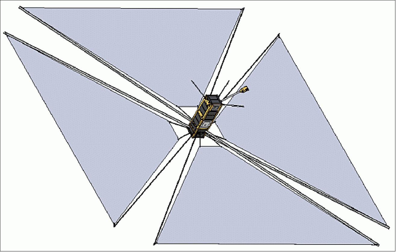
The CanX-7 mission involves a nanosatellite that will incorporate a lightweight, compact, deployable drag sail under development at SFL. The mission is funded by DRDC (Defence R&D Canada), Ottawa, NSERC (Natural Sciences and Engineering Research Council) of Canada, and COM DEV Ltd. The mission will demonstrate the drag sail's customizability, modularity, stowability and effectiveness at achieving the deorbiting requirements of the IADC. The results will then be used to create a low cost, modular, and customizable deorbiting device for nanosatellites and microsatellites in low Earth orbit, thus alleviating the programmatic and technical risk to space missions when using satellites of this class.
The goals of the CanX-7 mission are: 4)
• Demonstrate a deorbit device for CubeSats
• Validate post-deployment deorbit and attitude models
• Operate a secondary payload, namely an aircraft ADS-B (Automatic Dependent Surveillance - Broadcast) receiver, provided by COM DEV Ltd. The objective is to demonstrate whether a spaceborne ADS-B technology can be used to provide a source of continuous surveillance for commercial aviation.
Deorbiting Methods
Deorbiting is particularly challenging for micro and nanosatellites, as they are limited in terms of mass and volume. Consequently, there is currently no mature deorbiting technology targeted towards this class of satellite. As regulatory bodies around the world begin to enforce the IADC deorbit guidelines, this will represent a major roadblock for the small satellite community. The CanX-7 mission was initiated to proactively address this problem. Several potential deorbiting technologies, both active and passive, were considered including propulsion, solar sails, electrodynamic tethers, inflatable drag devices, and mechanically deployed drag devices. Ultimately, it was concluded that a mechanically deployed drag sail is the most promising option for LEO nanosatellites.
For most small satellites in LEO (Low Earth Orbit), the only viable means of achieving end-of-life disposal is to deorbit. In some cases, the inherent characteristics of a satellite (i.e. its ballistic coefficient) and its altitude are such that the satellite will naturally deorbit within 25 years or less. However, in many cases, because of either high ballistic coefficient or relatively high altitude, deorbiting must be accomplished using a dedicated system. Several approaches to deorbiting exist, and can be broadly categorized as either active (i.e. requiring continuous operation, usually steering) or passive (i.e. requiring only deployment to effectively deorbit, with no attitude control needed). 5)
Active methods
Active methods of deorbiting require attitude control beyond the end of spacecraft life, by definition. Maintaining such attitude control either requires the satellite attitude control system to be functioning properly (which cannot be assured at end-of-life) or necessitates an additional (integral) deorbiting attitude determination and/or control system, which increases complexity and cannibalizes precious mass and volume (both of which are at a premium in small spacecraft). Examples of active approaches include propulsion systems and controlled (steered) solar and drag sails.
The most traditional active method for deorbiting is to use a propulsion system. However, the problem with propulsive deorbiting is that you must be able to point the thruster—which, as described, implies the ability to control (or at least determine) the attitude of the satellite, which cannot be assured beyond EOL. Notwithstanding this consideration, propulsive deorbiting also requires additional propellant, which drives spacecraft mass. For larger satellites that already require high-performance orbital maneuvering systems, the additional ΔV to deorbit may be a manageable penalty, but for smaller satellites the added mass, testing and handling complexity can be deal breakers.
Controlled solar or drag sails have been proposed, in which the sail orientation is constantly controlled relative to either the solar vector for steered sailing or the satellite velocity vector to maximize drag. These approaches have the same drawback as using propulsive techniques, in that they must be continuously controlled—however, in the case of active solar or drag sails, instead of needing to maintain attitude for several minutes to execute the deorbiting maneuver, continuous attitude control may be required for months or even years! This is a significant burden to impose on a mission—particularly a small space mission, whose operations budget may have long since been exhausted at end of mission.
For these reasons, active approaches that require post-EOL control are viewed less favorably than passive methods for single- or multi-smallsat missions.
Passive methods
In contrast to active approaches, passive techniques do not require the satellite to remain operational during the deorbiting phase. Passive methods require no active control, relying only on natural perturbations and forces to accomplish deorbiting, and are therefore intrinsically much simpler than active methods. Examples of passive methods include drag sails, balloons, and ribbons or tethers. Passive systems are generally viewed here as preferable to active systems, given their "turn-key" characteristics—once a passive system is activated, it requires no long-term control or maintenance.
Tethers have often been advocated as promising deorbiting technologies for small satellites. However, such devices are usually extremely large when deployed (often hundreds of meters), have complex deployment (and deployed) dynamics, and have a demonstrated propensity to tangle and sever. Alternative concepts, such as inflatable balloons or inflatable drag sail devices, require the use of pressurized gas, which is problematic both for launch and for long-term leak-free storage. Inflatables can also be critically vulnerable to MMOD (Micrometeorite and Orbital Debris) punctures, which is problematic for worst-case deorbiting durations. Techniques for rigidizing inflatables following deployment to address MMOD concerns have been proposed, but add complexity and testability challenges.
Contrary to the above options, passive, mechanically-deployed drag sails offer a promising approach to deorbiting. Such drag sails are passive, requiring no attitude control—decidedly preferable to active methods—and they can be deployed using only stored mechanical energy, without pressurants or pyrotechnics.
Deorbiting Device "Killer Trades": A comparison of common deorbit approaches discussed for small LEO spacecraft is provided in Table 1, in which the so called "killer trades" of each option—the driving requirements, constraints and risks inherent in each—are summarized. Of the options presented in Table 1, mechanically-deployed drag sails are viewed as most promising for deorbiting nano- and microsatellites below a certain size, provided the orbit altitude is sufficiently low to allow drag-based deorbiting. Mechanically-deployed drag sails offer the benefits of small characteristic dimension, no attitude control requirements, and no pressurized gasses, instead using only their own stored mechanical energy for deployment. For these reasons, the development of a drag sail-based deorbiting technology has been selected by SFL for CanX-7, as well as future missions.
Deorbit approach | Active/passive | Killer trades |
Propulsion | Active | - Requires high total impulse (challenging for small satellites) |
Solar sail | Active | - Requires active pointing / steering |
Electrodynamic or drag tether | Passive | - Large characteristic dimension |
Inflatable drag device | Passive | - Requires long-term, leak-free storage of compressed gas |
Mechanically-deployed drag device | Passive | - Requires storage of mechanical energy |
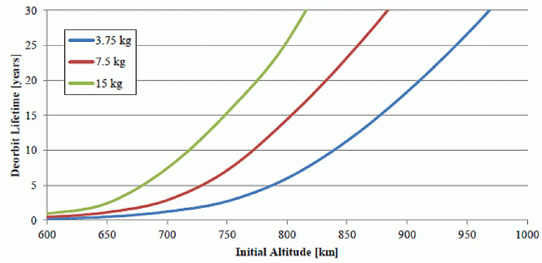
For a given drag sail cross-sectional area, deorbit performance degrades with both increase in orbit altitude and spacecraft mass. Using the variable-attitude analysis approach for a passive drag sail equipped spacecraft presented in (Ref. 3) coupled with STK's lifetime analysis tool, Figure 2 shows the effect of both initial orbit altitude and spacecraft mass on deorbit lifetime when using a 4 m2 drag sail. The results indicate that a drag sail deorbit device is suitable to meet the IADC's deorbit guidelines. Specifically, a 4 m2 drag sail is appropriately sized for satellites having mass up to about 15 kg, and orbit altitudes up to about 800 km. For the CanX-7 spacecraft whose mass is approximately 3.75 kg, the initial altitude could be as high as 940 km while still meeting the IADC's deorbit guidelines.
Thin film materials have extensive space heritage, having been predominantly used for spacecraft thermal control solutions in multi-layer insulation. Cutting-edge technologies such as drag sails and solar sails are now being developed using thin film materials in ways and environments not previously considered. The effectiveness of a drag sail, which is measured by the time it takes to de-orbit a satellite, depends on the projected cross-sectional area of the deployed sail membrane. Thin film materials are lightweight and compactible, therefore making them ideal for use as the sail membrane. The challenge of successfully implementing a deorbit device using thin films is due to the hazardous environment of low-Earth orbit, which the films must endure for many years. The main hazards include micrometeorite and orbital debris impacts, atomic oxygen erosion, and thermal degradation. 6)
The RAIKO CubeSat demonstrated the first dedicated drag sail scaled to deorbit a nanosatellite with a 50 cm x 50 cm aluminized polyimide sail from an orbital altitude of 300 km.
Spacecraft
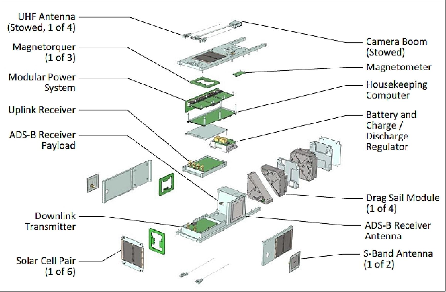
The CanX-7 nanosatellite will utilize the highly capable and proven 3U CubeSat form factor. It will use passive thermal control and electronics currently used by the GNB (Generic Nanosatellite Bus) satellite series as several components used on the CanX-2 nanosatellite are no longer available. Hence, an upgraded CanX-2 class bus is being used with a size of 10 cm x 10 cm x 34 cm. The estimated mass budget is ~3.75 kg. 7) 8) 9) 10)
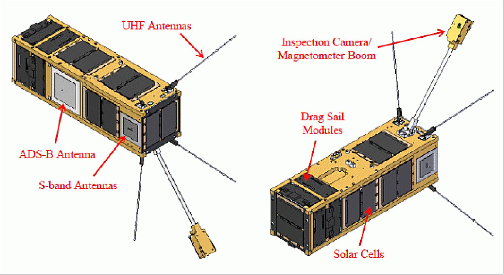
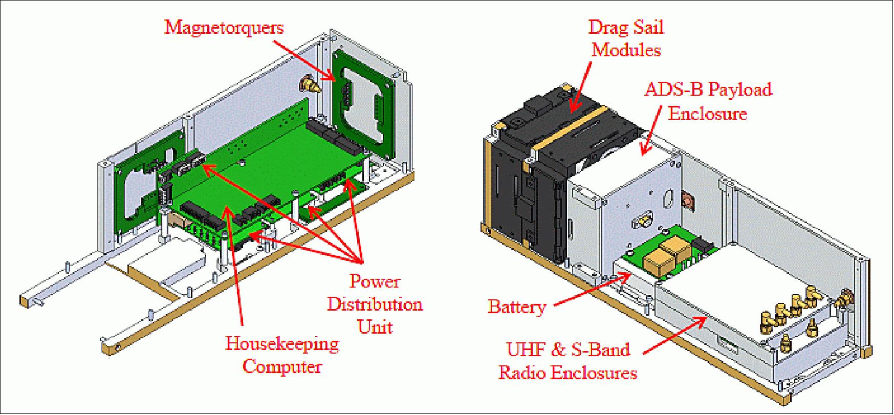
ADCS (Attitude Determination and Control Subsystem): Use of a 3-axis magnetometer (with flight heritage on AISSat-1) and panel currents for attitude determination. For attitude control, CanX-7 will utilize a set of three orthogonally printed magnetorquers, custom designed at SFL, each of which produces a maximum dipole of 0.2 Am2. The printed torquers will be used on AISSat-2, which is to be launched prior to CanX-7, and therefore will have earned flight heritage when CanX-7 is ready to launch. The torquers will be used to detumble the satellite after ejection and also in case of a spin up. They will also be used to orient the satellite in a favorable attitude prior to sail deployment to minimize any impact on communications.
EPS (Electrical Power Subsystem): The EPS is a DET (Direct Energy Transfer) system with PPT (Peak Power Tracking) functionality. A centralized PDU (Power Distribution Unit) based on the SFL Modular Power System provides switched power to spacecraft loads and collects power system voltage, current and temperature telemetry. EPS uses 8 body-mounted triple-junction solar strings. A Li-ion battery of 4.8 Ah capacity provides power during orbital eclipse periods. A battery heater is included to keep the battery within its operational limits. The battery is attached to a battery thermal control board located on the BCDR (Battery Charge/Discharge Regulator). The BCDR, in addition to monitoring the temperature of the battery, sets the operating voltage of the solar arrays, monitors battery voltage and regulates the charge and discharge current to the batteries.
The CanX-7 power demands range between 0.5-5 W with an average of 3 W of power generated by the solar array. The main power bus operates at 4.2 V which can be used directly by the loads without additional serial regulation.
C&DH (Command and Data Handling) subsystem: Use of generic nanosatellite bus electronics; single housekeeping microprocessor. The C&DH is responsible for communicating with the rest of the subsystems and relaying information between them.
TCS (Thermal Control Subsystem): The TCS is passive. This will be accomplished through thermal tapes, material selection and component layout. The main purpose of the thermal control subsystem is to keep satellite and its components within a temperature range acceptable for proper functionality. Heaters, as active measures for thermal control, are only used as a last resort for essential components unable to meet this temperature requirement through passive means.
TT&C (Telemetry Tracking and Command): Use of generic nanosatellite bus electronics; the uplink is provided in UHF band at 4 kbit/s, the downlink uses S-band . The UHF uplink uses an antenna system consisting of four canted monopoles that will deploy after ejection from the XPOD. This arrangement and the deployable mechanism, providing near omnidirectional coverage, are well established as they have been used on CanX-2. The S-band transmitter will provide the downlink capability for CanX-7 by utilizing two patch antennas. They are mounted on opposite faces of the satellite to provide near omnidirectional coverage over the full sphere of the satellite. The S-band transmitter nominally operates between 32 kbit/s and 1 Mbit/s. - Use of the existing SFL ground station in Toronto, Ontario, for spacecraft control and data reception.
Spacecraft form factor (3U CubeSat) | 10 x 10 x 34 cm |
Mass (including margin) | 3.75 kg |
Attitude control | ±10º (2σ) |
Attitude pointing mode | LMF tracking |
Power generation | 1.8 – 6.0 W |
Command uplink | UHF, 4 kbit/s |
Bus operational temperature range | -20ºC to +60ºC |
Launch interface | XPOD triple |
Launch
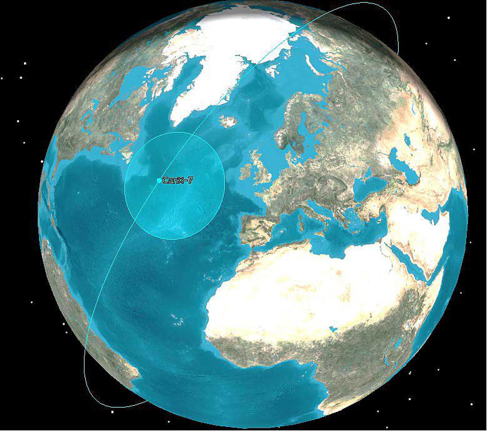
CanX-7 as a secondary payload was launched on Sept. 26, 2016 on the PSLV-C35 vehicle of ISRO from SDSC (Satish Dhawan Space Center) on the east coast of India. The primary payload on the flight was SCATSat-1 of ISRO. 11)
Orbit: Sun-synchronous orbit of SCATSat-1, altitude = 700 km, inclination = 98.1º, LTAN = 9:30 hours.
Secondary Payloads
• Pratham, a student-built nanosatellite (~10 kg) of IIT (Indian Institute of Technology) Bombay, India to study the ionosphere.
• PISAT, a student-built nanosatellite (5.3 kg) of PES University in Bengaluru, India. PISAT is a joint initiative of PES University and five other colleges. 12)
• BlackSky Pathfinder-1, a high-resolution (1 m) imaging microsatellite (~44 kg) of BlackSky Global. BlackSky Global is a commercial company of Seattle, WA, USA. The goal of BlackSky Global is to build a constellation of 60 satellites by 2019.
• AlSat-1N, AlSat-1B and AlSat-2B of ASAL (Algerian Space Agency), Algiers, Algeria. The three satellites were manufactured at SSTL partnership with Algerian engineers, ALSAT-1B is a 103 kg microsatellite based on the SSTL-100 bus. It carries an Earth imaging payload with panchromatic and multispectral cameras. AlSat-2B (117 kg) carries the NAOMI (New AstroSat Optical Modular Instrument). AlSat-1N (AlSat-Nano) is a 3U CubeSat which carries a technology demonstration payload as part of a partnership between ASAL and the UKSA (UK Space Agency).
• CanX-7, a nanosatellite (3U CubeSat, 3.5 kg) of UTIAS/SFL (University of Toronto's Institute of Aerospace Studies/Space Flight Laboratory), Canada.
Use of SFL's XPOD (eXperimental Push Out Deployer) for ejection of the CanX-7 nanosatellite into orbit. During launch, the drag sails and the deployables are in a stowed configuration. Once in orbit, CanX-7 will operate a secondary payload provided by COM DEV Ltd. for approximately six months.
DDS (Deployment Detection Subsystem): The objective of the DDS is to detect and verify the proper deployment of the drag sail. The DDS includes a COTS camera.
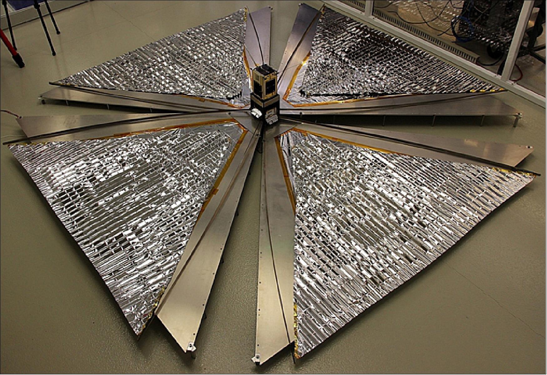
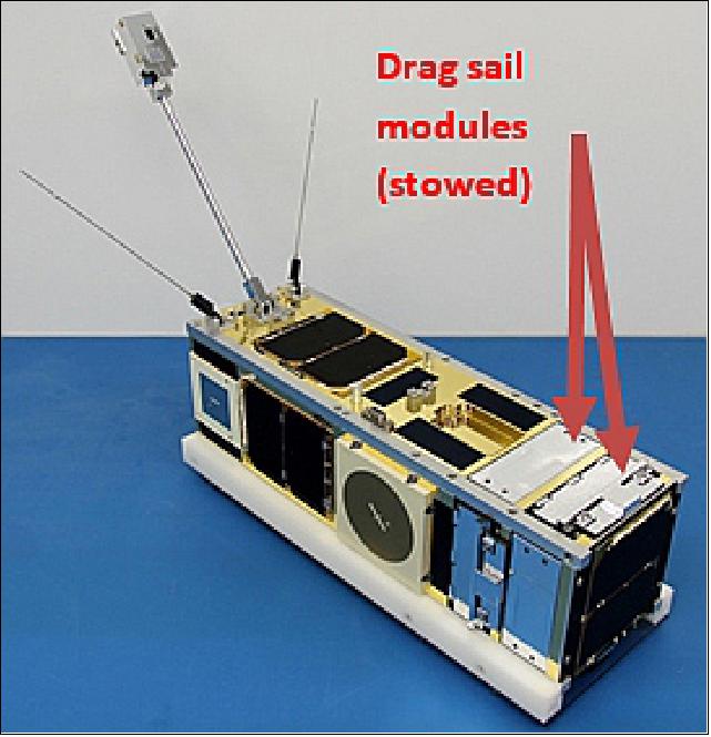
This drag sail payload is intended to be deployed at the end of a six-month phase of secondary payload operation. Sail deployment will be initially confirmed via on-board telemetry and images, while deorbiting performance will be verifiable within weeks following deployment. In order to provide a path towards adaptation on multiple satellite platforms, the CanX-7 drag sail payload is designed to be modular and scalable, consisting of four individual drag sail modules, each deploying its own independent sail. A total sail area of approximately 5 m2 is achieved with the full subassembly deployed.
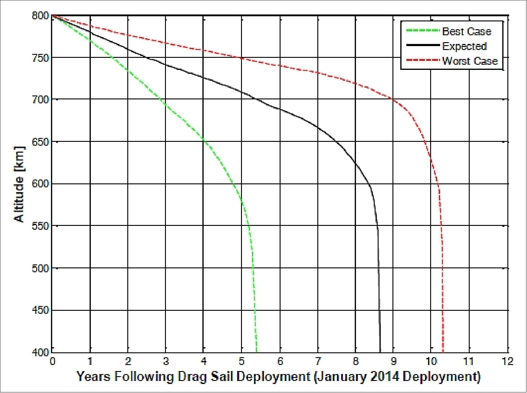
Figure 7 indicates that the CanX-7 spacecraft will deorbit within 5 to 10 years of initial deployment at its maximum design altitude, depending on LTAN and final spacecraft magnetic moment, which is uncontrolled on CanX-7 (Ref. 5).
Mission Status
• June 13, 2022: Space Flight Laboratory (SFL) announced the successful deorbiting of the 3.5kg CanX-7 demonstration nanosatellite using drag sail technology designed to reduce the time retired small satellites spend in orbit as space debris. CanX-7 burned up in Earth's atmosphere last month, just five years after drag sail deployment and roughly 178 years before it would have without any deorbit technology. 13)
- "The SFL drag sail technology developed for nano- and microsatellites is among the only commercially viable deorbiting devices available today, aside from propulsion," said SFL Director Dr. Robert E. Zee. "The drag sails performed better than designed, deorbiting CanX-7 in far less time than the maximum 25-year target recommended by the Inter-Agency Space Debris Coordination Committee (IADC)."
- CanX-7 was a 10x10x34cm nanosatellite built by SFL and funded by Defence Research and Development Canada, the Natural Sciences and Engineering Research Council, COM DEV Ltd., and the Canadian Space Agency. The satellite was launched in September 2016 with a two-fold mission of demonstrating Automatic Dependent Surveillance – Broadcast (ADS-B) message collection from space for global aircraft situational awareness, and then testing the deorbiting technology developed by SFL.
- SFL deployed the four drag sails – each about one square meter in area – on May 4, 2017, with the intent of decreasing the ballistic coefficient of the nanosatellite and using atmospheric drag to accelerate orbital decay. Mission participants observed an almost immediate change in altitude decay rate and continued tracking the orbital decay rate until CanX-7 re-entered the atmosphere on April 21, 2022.
- "Orbital debris is a big concern for the space industry, and the passive de-orbit technology demonstrated on CanX-7 is an advantageous solution for nano- and microsatellites," said SFL's CanX-7 Mission Manager, Brad Cotten. "The mission verified that SFL's lightweight drag sail technology is a more cost-effective and less complex method for deorbiting smaller satellites than traditional propulsion techniques."
- Additionally, the deorbiting technology allows nano- and microsatellites to be launched into a wider range of orbits than would be possible if natural orbital decay were to be relied upon, explained Cotten.
- CanX-7 project participants lauded the successful end to the mission, which is the first Canadian satellite to be independently deorbited by commanded atmospheric re-entry.
- According to Dr. Lauchie Scott, defence scientist with Defence Research and Development Canada, the CanX-7 drag sail deployment campaign provided a very rare opportunity to observe a satellite drastically change shape and size while being tracked by ground-based telescopes. This view showed the nanosatellite's brightness signature during the sail deployment and how its rotational motion evolved while the longer-term space sustainability deorbit experiment continued.
- Dr. Scott added that this was an outstanding Canadian collaboration to help mitigate risk from space debris.
- According to Dr. Brad Wallace, defence scientist with Defence Research and Development Canada, the project successfully proved that UTIAS/SFL's innovative drag-sail technology can deorbit a spacecraft decades faster than would have happened otherwise and demonstrated Canada's continued leadership not only in space technology, but also in responsible space stewardship. He added that the lessons learned from the CanX-7 mission will be used to help minimize the number of inoperable spacecraft orbiting the Earth, ensuring that space continues to be used to benefit Canadians and people around the world.
- SFL is a unique microspace provider that offers a complete suite of nano-, micro- and small satellites – including high-performance, low-cost CubeSats – that satisfy the needs of a broad range of mission types from 3 to 500 kilograms. Dating from 1998, SFL's heritage includes 61 operational successes and 31 currently under construction or awaiting launch. These missions relate to Earth observation, atmospheric monitoring, ship tracking, communication, radio frequency (RF) geolocation, technology demonstration, space astronomy, solar physics, space plasma, and other scientific research.
- In its 24-year history, SFL has developed CubeSats, nanosatellites, and microsatellites that have achieved more than 194 cumulative years of operation in orbit. These microspace missions have included SFL's trusted attitude control and, in some cases, formation-flying capabilities. Other core SFL-developed components include modular (scalable) power systems, onboard radios, flight computers, and control software.
• In mid-June 2017, just over one month since the CanX-7 drag sail was deployed, a preliminary deorbit profile for the CanX-7 spacecraft was generated by the UTIAS/SFL team (Figure 8), using information from TLE (Two-Line Element) sets provided by JPsOC. The change in altitude decay rate upon deployment of the drag sail is very evident, increasing from about 0.5 km/year to 20 km/year. This decay rate only holds true for the near-term; as the altitude decreases, the atmospheric density increases exponentially and therefore so will the decay rate. 14)
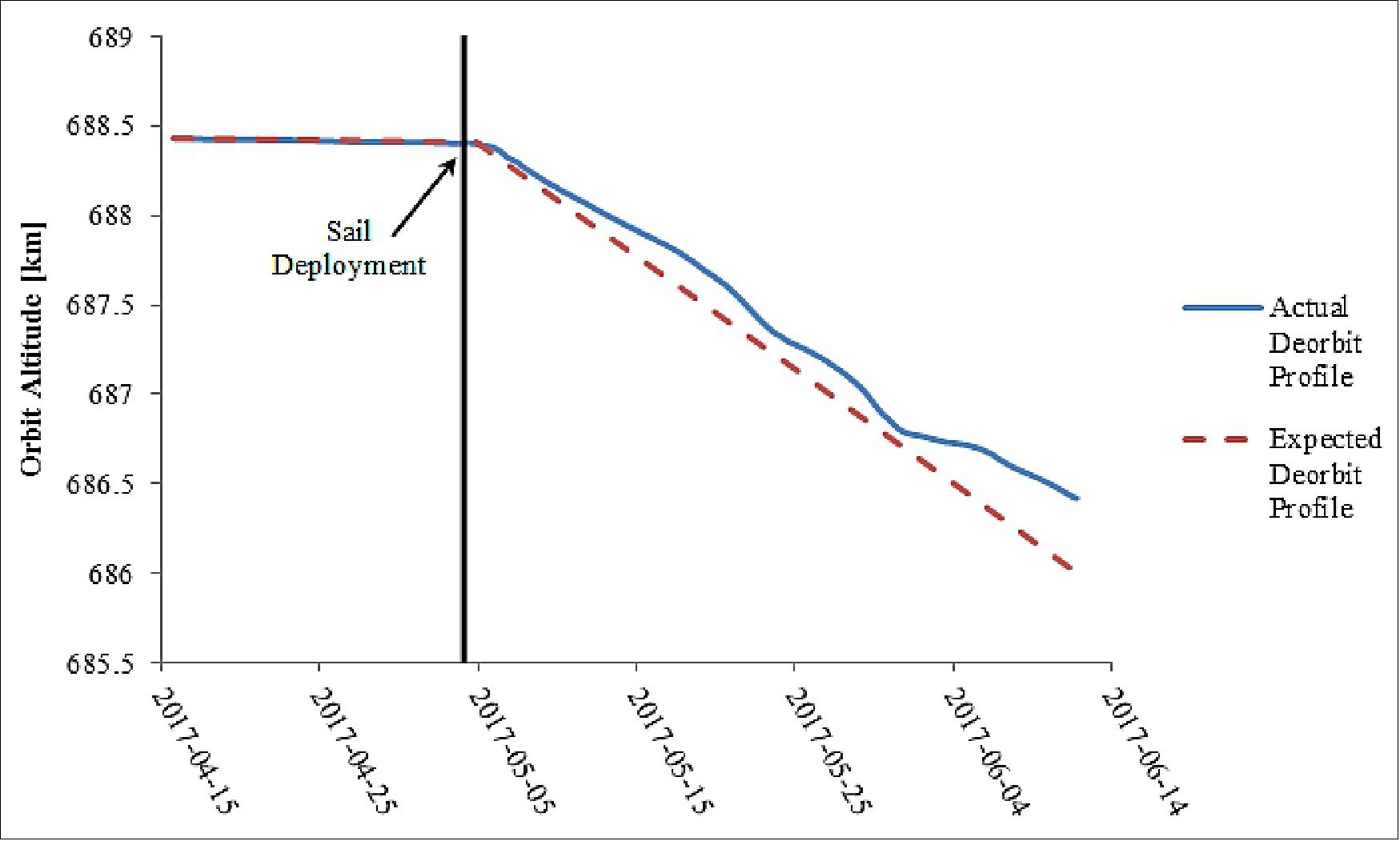
- The expected profile is generated using STK's (Satellite Tool Kit) lifetime analysis tool. For the expected profile, a drag coefficient of 2.2 is assumed, along with an effective drag area of 2 m2. In addition, the Jacchia 1970 Lifetime atmospheric density model is used. The effective drag area of 2 m2 is based on the attitude profile for the spacecraft during the month following deployment, during which the spacecraft was tumbling. The spacecraft tumbling is the result of disturbance torques acting on the spacecraft due to solar pressure, drag pressure, interactions with Earth's magnetic field, and interactions with Earth's gravity. These disturbances are amplified due to small variations in properties from sail segment to sail segment, including drag area, center of pressure, drag coefficient, and solar reflectivity. As the orbit altitude decreases, drag effects will begin to dominate the other disturbances forces and the spacecraft will begin to aero-stabilize, thereby increasing the effective drag area.
- The difference between the actual and expected profiles is relatively small and can be accounted for by small errors in the expected drag coefficient or the drag area. Due to the unique nature in which the sail segments are folded and unfolded, the resulting surfaces have both small and large wrinkles. This makes it difficult to precisely predict the drag coefficient. The wrinkles also make it difficult to precisely estimate the projected drag area. Errors in the atmospheric density model could also account for the discrepancy.
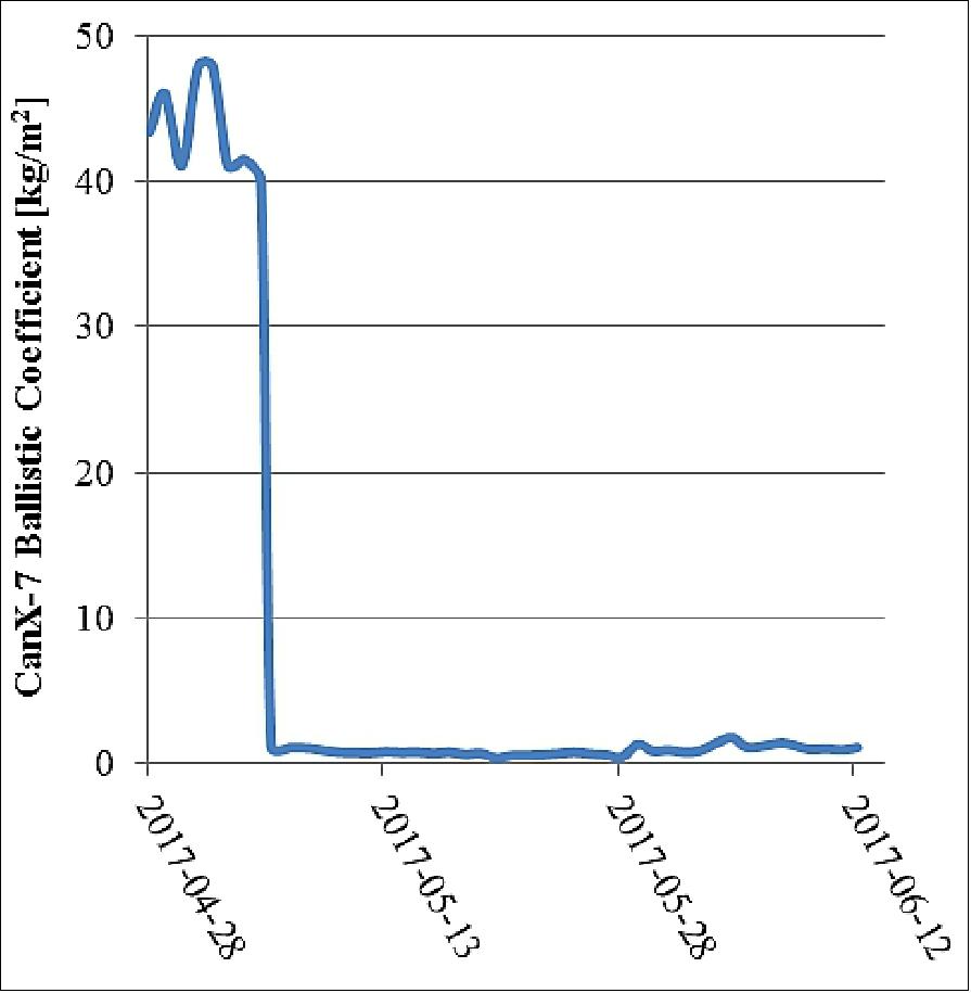
- In addition to the change in decay rate, a significant change in spacecraft ballistic coefficient was observed. The ballistic coefficient is determined using information from TLE sets provided by JSpOC, and is plotted in Figure 9. Upon sail deployment, the ballistic coefficient decreased from an average value of 43 kg/m2, to a value of 0.88 kg/m2. Assuming a drag coefficient of 2.2, the post-deployment ballistic coefficient corresponds with an effective drag area of 1.85 m2. This is close to the expected effective drag area given the spacecraft attitude profile.
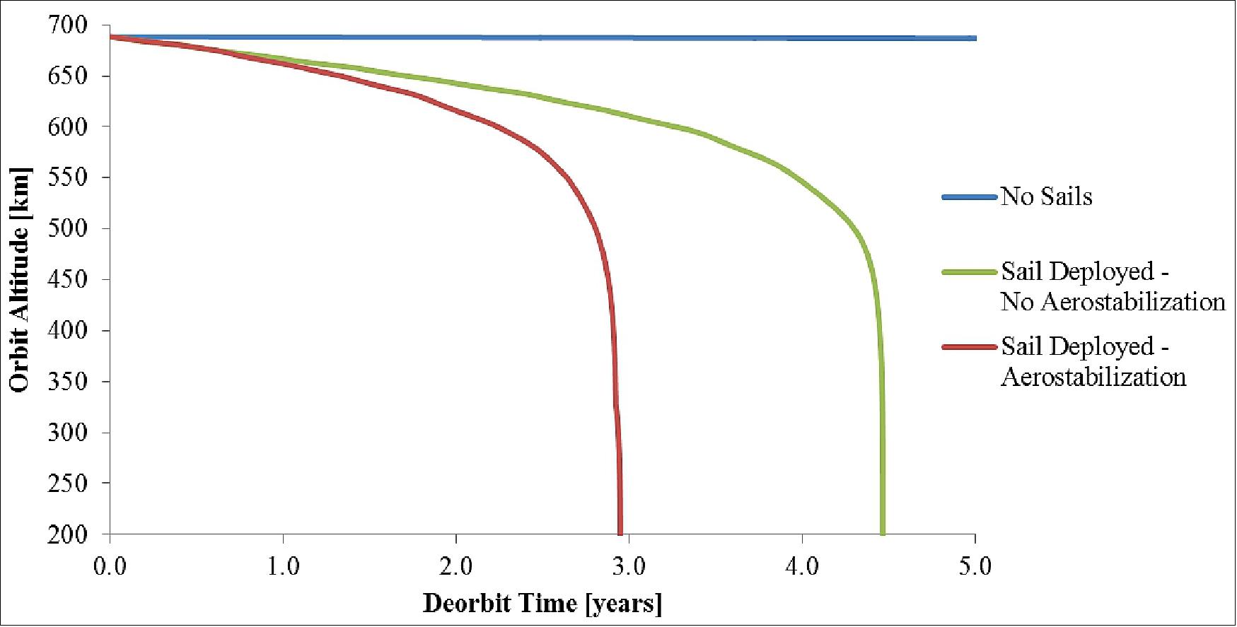
- Even though the deorbit phase of the CanX-7 mission has only been underway for about one month, the data gathered so far has been used to update the deorbit predictions for the spacecraft. These updated predictions are summarized in Figure 10. First, it is important to note the expected lifetime of the spacecraft if it did not have any drag sails. Without drag sails, it is expected that the CanX-7 satellite would remain on-orbit for 178 years, far exceeding the IADC 25 year guideline. With the sails deployed, and assuming the current attitude profile resulting in an effective drag area of 2 m2, the CanX-7 satellite would remain on-orbit for 4.5 years. This is a worst case scenario, as it is expected that the spacecraft will aero-stabilize as its altitude decreases. Due to the offset between the center-of-pressure of the sail segments and the center-of-mass for the spacecraft, CanX-7 benefits from the "shuttlecock" effect. This should cause the spacecraft to stabilize with the plane of drag sail perpendicular to the spacecraft velocity vector. At lower altitudes, the drag force will dominate over the other disturbance torques, allowing the aero-stabilized attitude to persist. Using the variable-attitude analysis approach for a passive drag sail equipped spacecraft 15), the actual expected lifetime for the CanX-7 spacecraft – assuming aero-stabilization – is 2.9 years. All lifetime estimates are given from the time of sail deployment (May 4th, 2017).
• May 11, 2017: After deploying its drag sails only a week ago, early results from CanX-7 indicate that the sails are having a noticeable effect. Figure 11 shows that the altitude decay rate changed significantly following the deployment in the late evening of 4 May 2017 (Toronto time). The figure also shows that the aerodynamic drag on the satellite has increased as a result of a changed ballistic coefficient. After a certain amount of time, it is expected that CanX-7 will aerodynamically stabilize due to the so-called "shuttlecock" effect, with all four sails to the rear of the satellite as it travels around Earth. "This is an earlier than expected positive result from CanX-7," explains Dr. Robert Zee, Director, SFL, "It confirms and validates the effectiveness of the drag sails in accelerating orbital decay." The CanX-7 deorbiting demonstration is intended to space qualify the SFL-developed drag sail technology. The technology can then be used with confidence to ensure that small satellites comply with IADC (Inter-Agency Space Debris Coordination Committee) guidelines for space debris mitigation. It is an important technology for ensuring that the environment is kept safe for future generations of low Earth orbit missions. 16)
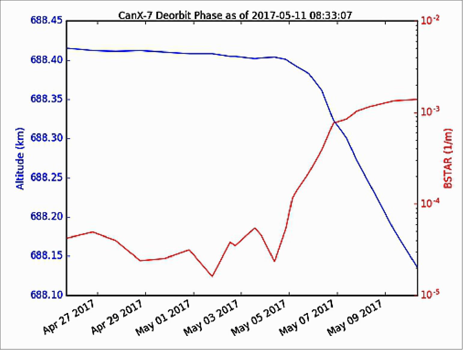
Legend to Figure 11: BSTAR (B*) is a way of modeling aerodynamic drag on a satellite in the SGP4 (Simplified General Perturbation 4) satellite orbit propagation model.
• May 3, 2017: After collecting over 4.3 million ADS-B (Automatic Dependent Surveillance – Broadcast) messages from aircraft since it launched in September 2016 to the ISS and deployed thereafter into space, the 3.5 kg 10 x 10 x 34 cm CanX-7 nanosatellite (Figure 12) deployed its four (4) drag sails on May 3, 2017 — and started its deorbit mission. Each sail has an area of approximately 1 m2 (Figure 6). 17) 18)
- The sails are intended to decrease the ballistic coefficient of the satellite and use atmospheric drag to accelerate orbital decay. The drag sail technology is important for nano- and microsatellites whose low Earth orbital presence would exceed the IADC (Inter-Agency Space Debris Coordination Committee) guidelines that limit such presence to 25 years after end of mission. "With SFL's innovative drag sail technology verified on orbit, the door is opened to using this technology on future missions where compliance to IADC guidelines would not otherwise be possible," says Robert Zee, Director of SFL, "Such compliance is essential to ensuring that space debris is mitigated for the world. It is also a critical component in satisfying regulatory bodies so that small satellite missions may proceed uninhibited."
- CanX-7 completed a seven (7) month campaign to collect ADS-B messages from aircraft to demonstrate Canada's first ADS-B data collection from space. With that phase of the mission successfully completed, the drag sails were deployed to begin the second phase of the mission. The sequential phases were intended to emulate an operational mission followed by deorbiting. A key component in the drag sail technology demonstration was long-term stowage of the drag sail modules in space without interrupting or affecting the operational mission. "We want our drag sail technology to be compact and non-intrusive to a satellite's main mission. This will ensure wide acceptance and easy adoption by future microsatellite missions," says Zee.
- "The four drag sails were deployed across the two passes this evening (May 3, 2017, two sails per pass)," reports Brad Cotten, CanX-7 Project Manager. "All telemetry is nominal and indicates that each sail is fully deployed. The deployment was also confirmed optically from the ground." During this final phase of the CanX-7 mission, the deorbiting process will be closely monitored via the SFL ground station in Toronto. The orbital decay rate will be determined and compared against pre-launch simulation results. "We are thankful to our sponsors that helped make this mission successful for the benefit of Canada and the world, including Defence R&D Canada – Ottawa, the Natural Sciences and Engineering Council of Canada, COM DEV, Royal Military College of Canada, and the Canadian Space Agency."
• April 2017: Air traffic control agencies have been seeking to track aircraft from space via ADS-B since the PROBA-V mission first detected them in 2013, with the goal of being able to track aircraft at any location on the globe in realtime. By tracking aircraft all the way from takeoff to landing, they can follow more optimal routes by safely flying closer together, thus increasing the safety of commercial air travel, while reducing fuel costs and environmental impact. Currently, aircraft flying over areas without realtime surveillance must adhere to strict spacing guidelines in order to prevent collisions. The spacing guidelines for aircraft flying over the North Atlantic Ocean, a prime example of an area that could benefit from space-based tracking, require aircraft to use one of several paths when traveling from Europe to North America, only one or two of which may be optimal given their destination, the type of aircraft, and prevailing winds. 19)
The CanX-7 nanosatellite mission is a technology demonstration mission developed by the Space Flight Laboratory, launched in September 2016. The spacecraft bus is based on SFL's successful CanX-2 bus, and is approximately the same size as a 3U CubeSat. CanX-7 incorporates numerous technologies into its design, including a modular power system, a magnetics-only attitude control system, deployable drag sails, and an ADS-B receiver. The primary mission objective for the spacecraft is to validate the use of a modular, deployable drag sail device for the deorbiting of the spacecraft. The ADS-B receiver will operate as a secondary payload for a total of six months, collecting data, after which the attitude control system will be turned off, and the drag sails deployed. The spacecraft is expected to deorbit over the following two years, during which time a deorbit model for the spacecraft will be validated.
The CanX-7 ADS-B Receiver
The primary mission objective for the spacecraft is to validate the use of a modular, deployable drag sail device for the deorbiting of the spacecraft. The ADS-B receiver will operate as a secondary payload for a total of six months, collecting data, after which the attitude control system will be turned off, and the drag sails deployed. The spacecraft is expected to deorbit over the following two years, during which time a deorbit model for the spacecraft will be validated.
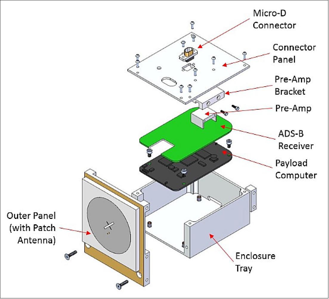
The CanX-7 ADS-B payload was developed in partnership with the Royal Military College of Canada. The flight payload was finalized after several design iterations and experience gained through testing earlier versions on high-altitude balloons. The final design consists of a payload computer, receiver and FPGA board, external pre-amplifier, and patch antenna. The receiver and payload computer are commercial off-the-shelf products with hardware modifications that allow for reduced power consumption and improved reliability. The payload uses a mix of commercial and custom designed software in order to decode the ADS-B messages, manage files, and to command and telemeter the payload. A low profile patch antenna was chosen due to mechanical constraints imposed by the spacecraft bus. The patch antenna was designed to have the desired gain and polarization characteristics. In order to verify the performance and space worthiness of the payload, it was subjected to a unit level thermal sensitivity test campaign, and spacecraft level thermal vacuum, vibration, and electromagnetic compatibility testing. Based on the results of the test campaign, a simulation was created in order to predict expected on-orbit performance of the receiver.
On Orbit Operations: In operation, the ADS-B payload collects ADS-B messages for approximately 18 minutes per orbit, limited due to the power generation ability of the spacecraft bus. This operations scheme results in ample data to validate the performance of the ADS-B payload. Original specifications for the ADS-B payload required only two minutes of data collection per orbit, but favorable orbit and power saving measures implemented on the payload allowed that duration to be increased considerably.
Each orbit, a particular geographic area is targeted for data collection. The primary location of interest for the CanX-7 mission is the North Atlantic. The first month of operations focused on this area, typically recording messages at mid-latitudes between 20° and 80°. Due to the better than expected data throughput, many geographic regions have been targeted since including Australia, North America, Europe, and the North Pole. A full month of data was collected from the Southern Hemisphere, targeting Australia in particular. Australia has an extensive infrastructure of ground based ADS-B receiving stations allowing for a good set of ground truth data to compare against that collected on-board CanX-7.
Preliminary Results: As of January 2017, the ADS-B receiver continues to perform very well, with over 2.25 million messages received in the four months since regular operations began in early October 2016. Most of the messages collected are from the Northern Hemisphere, due not only to the increased amount of time spent recording there, but also due to the relatively large number of commercial aircraft routes compared to the Southern Hemisphere. CanX-7's recordings are biased towards the mid-latitudes, as can be seen in Figure 15. This is a result of the local magnetic field tracking attitude control scheme and Earth's magnetic field profile, making it less suitable to point the ADS-B antenna towards the Earth while over the equator. Performance has been good over areas of interest, particularly the North Atlantic Ocean and Australia, but also North America, Europe, China, and India.
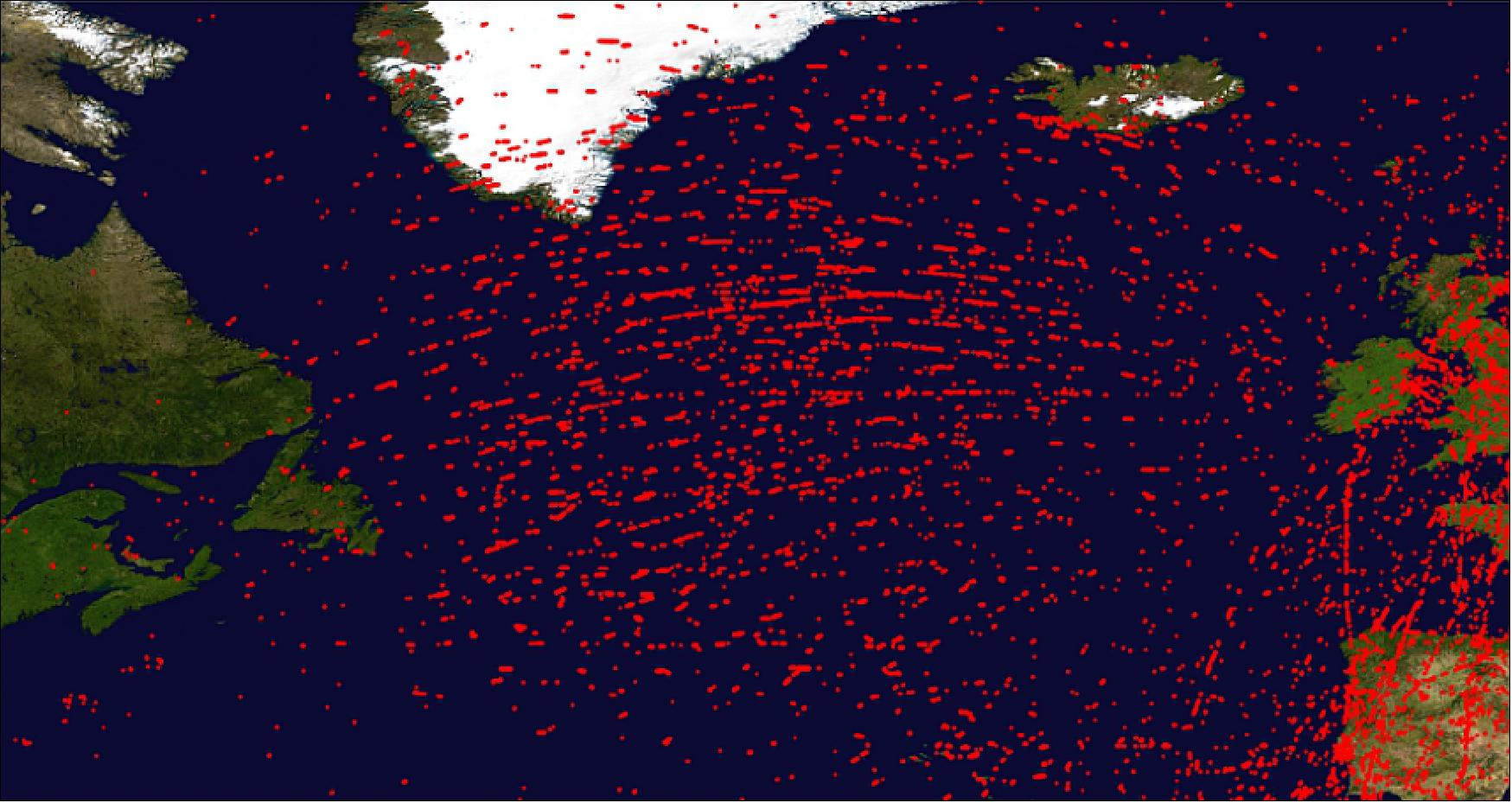
The ADS-B receiver collects messages at a rate 166% higher from mid-latitude, Northern Hemisphere operations than from mid-latitude Southern Hemisphere operations, due to large areas without high-traffic commercial routes. While over the North Pole, CanX-7's antenna is pointed in the nadir direction, but aircraft transmitting antennas have a gain null in the vertical direction. This, along with fewer commercial routes than the mid-latitudes, means that the message collection rate during Northern Hemisphere mid-latitude operations is 207% higher than Northern Hemisphere polar operations. Very few flights fly over the South Pole, so the ADS-B receiver is not operated over this region.

The successful CanX-7 mission has shown that a small, inexpensive spacecraft can be used to detect ADS-B messages from space. This opens the door to the use of other small, inexpensive satellites for tracking aircraft in an operational capacity. By using the small satellite approach, a large constellation of ADS-B satellites could be built at a cost on the order of tens of millions of dollars, rather than hundreds of millions. The low power and small size requirements demonstrated for a working ADS-B receiver also allow for individual satellites to be smaller, reducing launch costs and complexity. This reduction in cost and size assists in making commercial cost models realizable.
• February 18, 2017: The CanX-7 satellite is operational. At the present it is collecting data with its ADS-B receiver and downlink that to the ground. Likely in a few months, the drag-sail payload will be deployed. 20)
• October 4, 2016: The ADS-B (Automatic Dependent Surveillance-Broadcast) receiver on CanX-7 is a technology demonstrator for spaceborne monitoring of air traffic. 21)
• September 26, 2016: The satellite was contacted and found healthy during its first pass over Toronto several hours later. 22)
- Commissioning of CanX-7 will continue into October. Following this, the ADS-B aircraft tracking receiver will be tested over a six-month period. Upon completion of the ADS-B demonstration, CanX-7's four drag sails will be deployed one at a time, while being monitored by on-board cameras. The deorbiting progress will then be observed over the course of several years.
Experiments (Drag Sail, ADS-B)
Drag Sail
The selected drag technology to be demonstrated on the CanX-7 mission must be capable of deorbiting CubeSats within the IADC required timeline. Several devices that can be utilized as deorbiting devices for small satellites include: rockets, inflatables, rigidizable inflatables, electrodynamic tethers and drag sails. Several requirements that the drag device had to satisfy included being a passive device that does not require an active satellite to deorbit, require no high pressurized containers to deploy which could potentially complicate obtaining a launch, and be testable in a 1-g environment to allow for testing prior to flight (Ref. 7).
The drag sail was concluded to be the proper fit for deorbiting CubeSats. Other potential methods had several complications or didn't meet one or more of the requirements, making the development or inclusion a higher risk to the demonstration mission.
CanX-7 will accomplish its main objective by employing four deployable drag sails, each stowed within its own module, to demonstrate the ability to deorbit at different rates while maintaining some redundancy in the deorbiting system for the purpose of experimentation. These drag sail modules have either superior or competitive packaging and mass efficiency to state-of-the-art solar sails; and even at the demonstrator scale represent a sail design for CubeSats, instead of a sail that simply fits inside a CubeSat, while precluding any other useful payload. CanX-7 will also be used to validate deorbit models to aid in the deorbiting analyses of future SFL satellites.
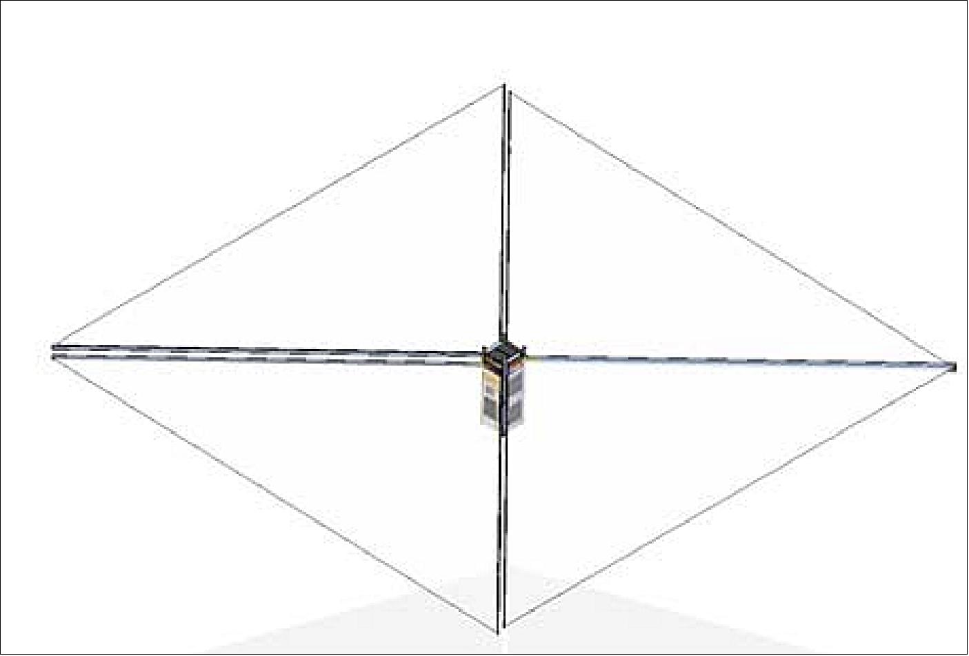
At the end of mission operation, the drag sail modules will be deployed in order to deorbit the satellite, as shown in Figure 17.
By demonstrating the success of the deorbiting solution on-orbit, the drag sail will earn flight heritage, which will enable easier adoption into future missions. In using this deorbiting technology (or larger upgrades) on future SFL satellites, the laboratory is helping to mitigate the global problem of orbital debris.
Lifetime analysis
The drag sail device is required to deorbit its host spacecraft within 25 years to meet IADC guidelines. It was sized with the aim of deorbiting a reference spacecraft which is larger than CanX-7. Sizing for a larger spacecraft increases the versatility of the drag sail and will also facilitate a rapid (much less than 25 year) demonstration of the deorbit technology during the CanX-7 mission. Early on in the development of the drag sail, an area of 4.0 m2 was chosen to be sufficient to meet both of these objectives (Ref. 7).
Various analyzes were completed in order to determine the required drag area to deorbit within the set period of 25 years. The drag sail was chosen as the deorbit device to demonstrate on the CanX-7 mission and therefore the expected lifetime and performance for this device had to be analyzed prior to beginning the detailed design of the drag sail device.
Methodology: A combination of fixed-attitude and variable-attitude simulations were performed in order to evaluate the deorbit performance of the CanX-7 drag sail. The fixed attitude simulations were performed using the deorbit toolbox in STK (Satellite Tool Kit) and served as a baseline against which the variable-attitude simulations could be compared. The variable-attitude simulations were performed using a quasi-coupled, orbit-attitude dynamical numerical integrator using MATLAB/SIMULINK. The term ‘quasi' here refers to the fact that fully-coupled attitude orbit simulations were not performed. Instead, the approach was to perform short-term, variable attitude simulations for many fixed orbits; the results from each of these static orbit cases were then combined to evaluate the overall performance of the drag sail over the deorbit lifetime.
Constant-Attitude (STK) Simulations: An analysis was carried out to determine the required drag area of the sail in order to meet the lifetime requirement. STK software was used to model the satellite with the HPOP (High Precision Orbit Propagator). STK was used to get an idea of lifetimes for different sized satellites.
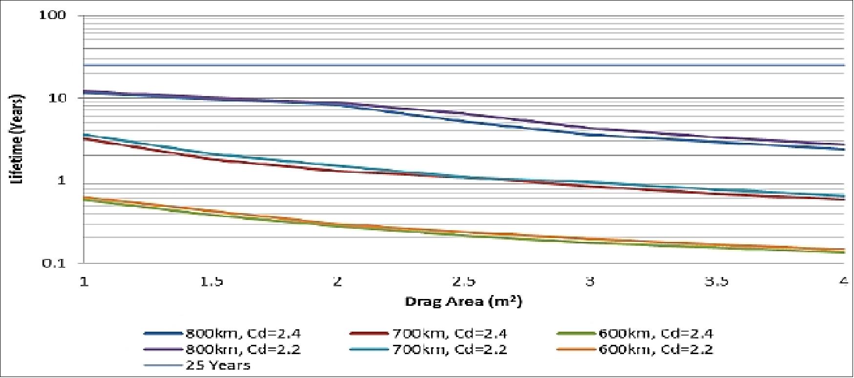
The STK simulations for the CanX-7 satellite were completed at several different altitudes, chosen based on the altitudes of current and future satellite missions at SFL, as well as with drag coefficients of 2.2 and 2.4. The typically accepted value of 2.2 was found not to be representative of on-orbit conditions and 2.4 was found to be more realistic. For comparison, deorbit lifetime results using both drag coefficients are shown in Figure 18. The lifetimes for the CanX-7 satellite are well below the IADC recommendation of 25 years to facilitate a potentially quicker deorbit or to act as functional redundancy.
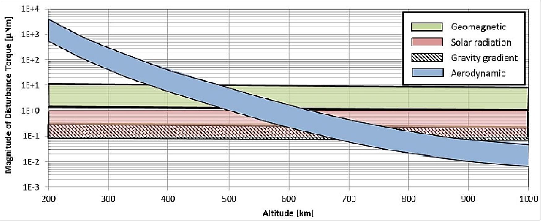
Variable-Attitude Simulations: The STK simulations described in the previous section do not account for the time-varying nature of the spacecraft's projected drag area. For on-orbit satellites, the instantaneous projected area will be a function of attitude. Even with an aerodynamic drag device which is designed to take advantage of the "shuttle cock" effect, achieving an aero-stable configuration is unlikely at altitudes above 650 km and perhaps even lower depending on the spacecraft and sail properties. This can be realized by examining Figure 19 which shows the upper limits of disturbance torque magnitudes expected for a small satellite in LEO.
Note that in Figure 19, a band is shown for each disturbance; the band captures the range of maximum torque which is dependent on various spacecraft and environment parameters. It can be seen that above 600 to 650 km the geomagnetic disturbance due to the inherent residual magnetic dipole moments of the spacecraft will dominate. It is not until the altitude drops to around 450 km ,that the aerodynamic disturbance becomes dominant and aero-stabilization could be reasonably expected. This is especially difficult for highly asymmetric spacecraft such as CanX-7, which has a wide range of projected areas, varying from 0.034 m2 when the drag sail is edge-on to the velocity vector, to a maximum of 4 m2 when the drag sail is perpendicular to the velocity vector. In a word, relying on deorbit analyses which assume constant drag area could give very misleading results. It is therefore necessary to account for the attitude dynamics when assessing the deorbit performance.
Decoupling the Attitude and Deorbit Dynamics: Performing fully coupled attitude and deorbit simulations is impractical due to the very different associated timescales. To adequately simulate attitude dynamics, the required maximum time step is on the order of seconds. Propagating for a full 25 year deorbit period would require on the order of at least 100 million integration steps. Furthermore, due to the uncertainty in final spacecraft and orbit parameters, many such simulations must be performed to ensure the design meets the requirements in all expected configurations.
An alternative approach was developed which effectively decouples the orbit and attitude simulations. The methodology uses short-term (on the order of 10's of orbits) attitude simulations to evaluate the deorbit performance in individual slices of an entire solar cycle (approximately 11 years). The results from many of these slices are then combined appropriately to arrive at a result which approximates the deorbit performance for the entire solar cycle. The output of this analysis is referred to as the WSCEA (Whole Solar Cycle Effective Area) and can be compared directly against the constant-area simulations performed using STK to estimate the deorbit lifetime.
Design of Experiments: The primary system parameters which affect the WSCEA are: orbit altitude, inclination and LTAN (Local Time at the Ascending Node); spacecraft residual magnetic dipole; spacecraft mass MOI (Moment of Inertia), configuration of drag sail, and the inherent damping of the spacecraft (due to structural damping, magnetic eddy current damping, etc.). While some of these parameters can be estimated to a reasonable accuracy during the design and development of the spacecraft (i.e., spacecraft MOI and configuration of the drag sail), the rest will not be defined until the spacecraft is fully assembled and the operational orbit is selected. For this reason, a design of experiments was developed which enveloped all of the possible configurations of spacecraft and orbit.
Orbit and Spacecraft Configurations: The considered orbits were sun-synchronous orbits (SSO) with an altitude of 800 km which is the worst case from a deorbit performance point-of-view (note that the drag sail is designed to deorbit spacecraft with altitudes of 800 km or less). Although the drag sail is designed to work within any near polar orbit (with inclinations between 80º and 100º), only SSO were analyzed since they envelope the rest in terms of deorbit performance; if the orbit is not sun-synchronous, the performance tends to average out over time, having weaker performance with LTANs near 6:00 or 18:00 hrs, and increased performance with LTANs near 12:00 or 24:00 hrs. By considering orbits with constant LTANs, the upper and lower limits can be put on the expected performance. Table 3 shows a summary of the considered orbits.
Parameter | Considered values |
Altitude | 800 km |
Inclination | 80º, 90º, 100º |
Constant LTAN (Local Time at the Ascending Node) | 3:00 hr, 6:00 hr, 9:00 hr, 12:00 hr, 15:00 hr, 18:00 hr, 21:00 hr, 24:00 hr |
Aside from inherent damping, the residual magnetic dipole moment of a satellite is the spacecraft-dependent parameter that has the greatest effect on the deorbit performance, because it has the greatest impact on spacecraft attitude during periods when solar disturbances are low. To understand the sensitivity of deorbit performance to the magnitude and orientation of the residual dipole, seven spacecraft configurations were considered that envelope the expected design range for the CanX-7 spacecraft. Table 4 summarizes the considered configurations; the direction refers to the angle between the sail plane and the residual dipole of the spacecraft, when the dipole points in a direction parallel to the drag sail plane the angle is 0º.
| Spacecraft configuration | ||||||
1 | 2 | 3 | 4 | 5 | 6 | 7 | |
Magnitude [Am2] | 0 | 0.05 | 0.10 | ||||
Angle between drag sail plane and residual dipole | - | 0º | 45º | 90º | 0º | 45º | 90º |
Results: The results from the design of experiments are displayed in Figure 20 which shows the WSCEA (Whole Solar Cycle Effective Area) for orbits with altitude 800 km, inclination of 100º, and various LTANs; the results for other inclinations follow the same trend.
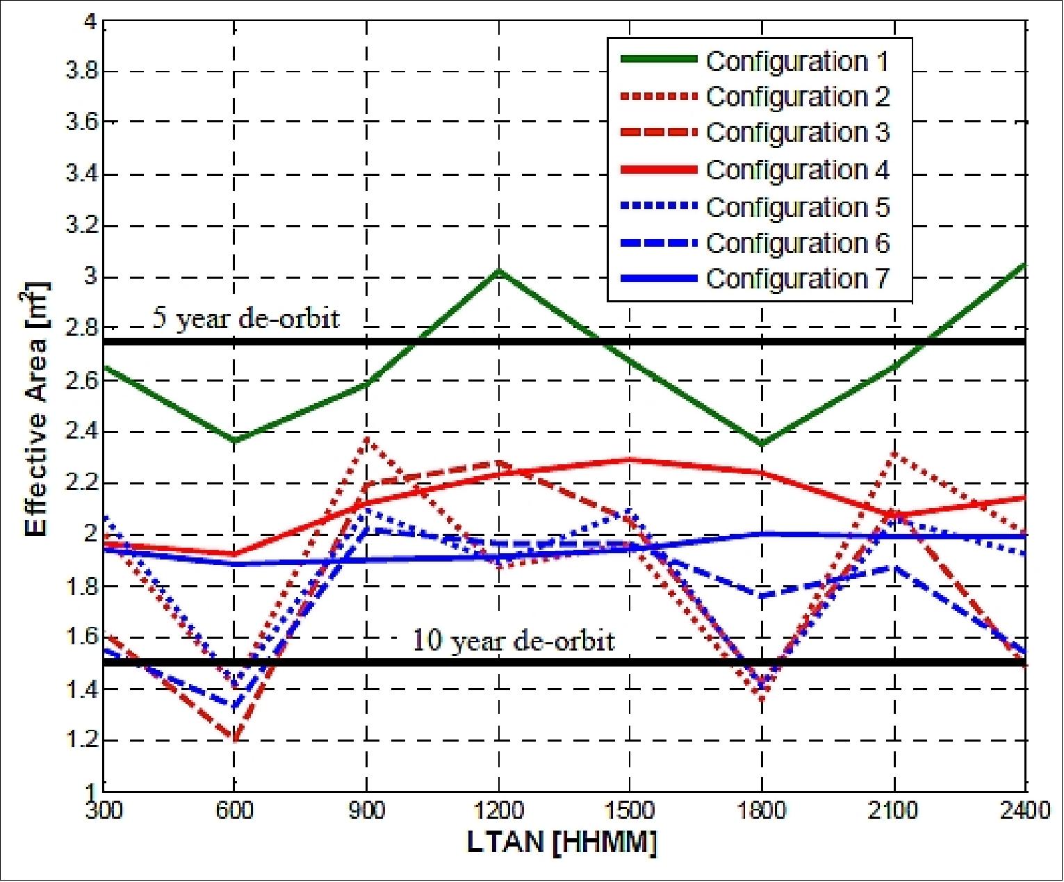
Deorbit lifetime for the CanX-7 mission: In general, the results indicate that the WSCEA for the CanX-7 mission will be between 1.2 and 3.0 m2 with an average of about 2.1 m2 (at the maximum initial altitude of 800 km). Comparing this to the results from the constant-area lifetime simulations shown in Figure 20, the deorbit lifetime from 800 km for the CanX-7 spacecraft will be between 4 and 10 years depending on the magnetic properties of the spacecraft. The 4 m2 SFL-designed drag sail is therefore sufficient to meet the deorbit requirements.
Drag Sail Design
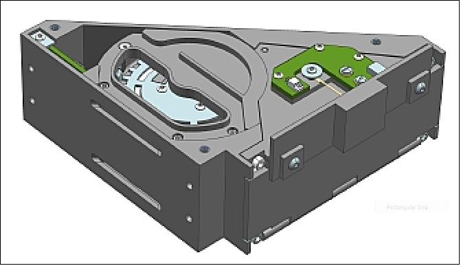
The CanX-7 drag sail payload design is modular, consisting of four separate sail modules which combine to form a subassembly that fits within the constraints of the 3U CanX-7 bus. Each individual sail in the subassembly can be released individually and commanded directly over the spacecraft uplink. The drag sail modules are wedge-shaped, and each deploys a trapezoidal sail supported at its corners. Figure 21 shows a single drag sail module in its pre-deployed state, while Figure 22 shows an exploded view. For CanX-7, the four modules are assembled in two decks, and mated to each other and the spacecraft with two interface brackets. This complete assembly is shown in Figure 23 (Ref. 5).
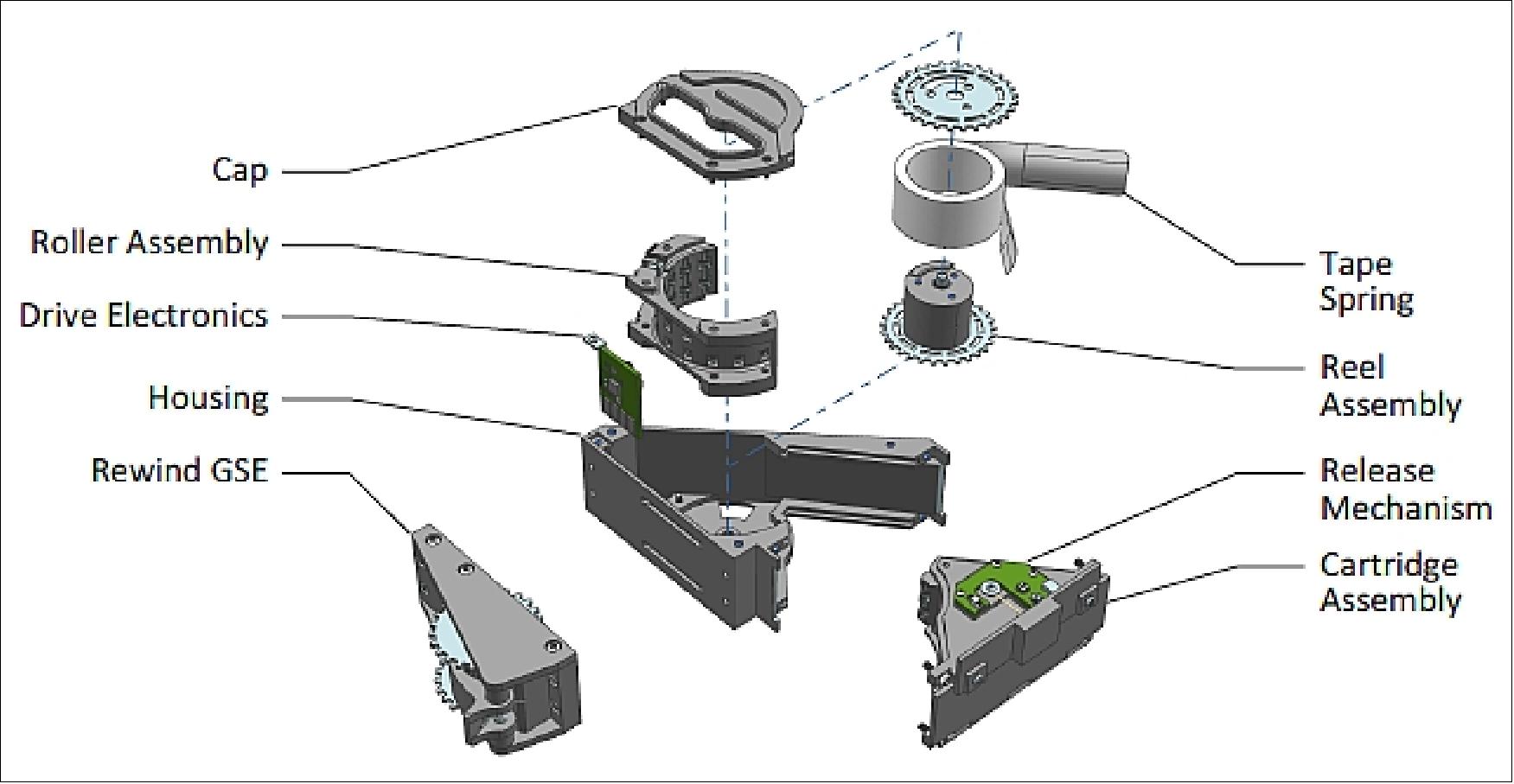
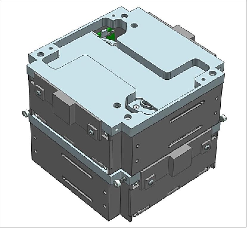
Sail module electronics: The sail module electronics are responsible for processing deployment commands sent from the ground; driving the release mechanism heater; and collecting telemetry on deployment confirmation and the extent of deployment. The sail is deployable only via ground command on CanX-7, requiring two separate ARM and FIRE commands sent in sequence to be initiated.
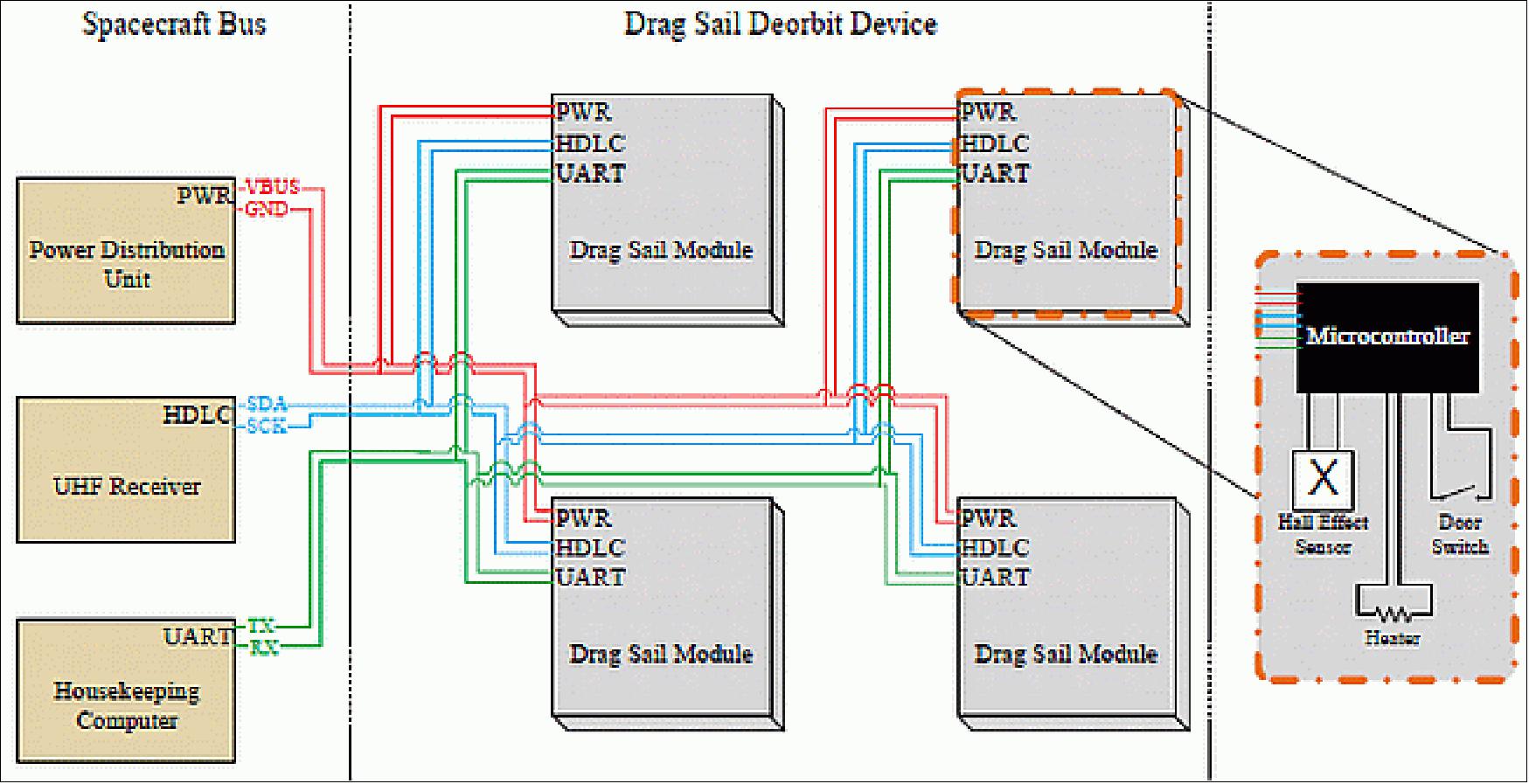
At the payload subassembly level, each drag sail module is connected to three multi-drop busses: a power bus; a telemetry bus (asynchronous serial) from the housekeeping computer; and a command bus (synchronous serial) from the UHF receiver. Figure 24 shows a high-level sail module interconnection diagram, in which each sail module is shown on the power and data busses that run through the sail subassembly.
At the individual drag sail module level, each unit contains its own compartmentalized telemetry and drive electronics, and the operation of each module is independent from adjacent modules. Each drag sail module contains:
• A microcontroller connected to the spacecraft's housekeeping computer and UHF receiver, which accepts commands to deploy the sail and transmits telemetry when instructed
• A driver circuit to monitor and activate the release mechanism heater
• A microswitch to detect whether the sail door is closed or open
• A Hall effect sensor to monitor motion of the boom reel.
The sail modules receive ARM and FIRE deployment commands directly from the spacecraft command uplink. The sail modules also receive commands and transmit telemetry to the spacecraft housekeeping computer through a dedicated serial interface.
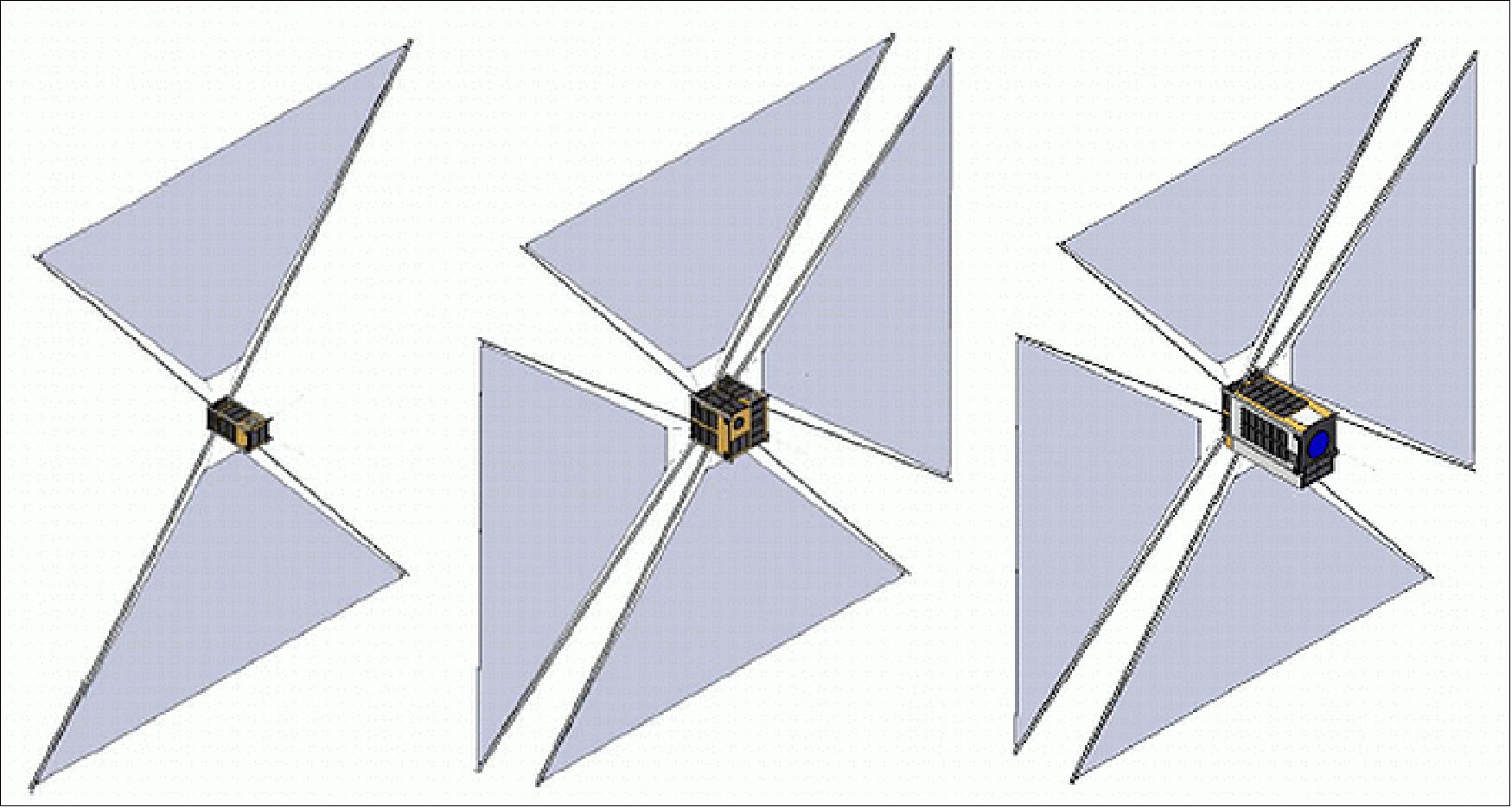
The drag sail modules are conceptualized to be compatible with the three standard UTIAS-SFL-made spacecraft buses as shown in Figure 25. Each drag sail module is triangular in shape, and deploys a 1 m2 triangular sail formed from metalized polymer film supported at each corner (Figure 26). Four modules are deployed to form a complete square sail. The plane of the drag sails is offset from the spacecraft's center of mass, creating the potential for an aero-stable attitude at low altitudes.
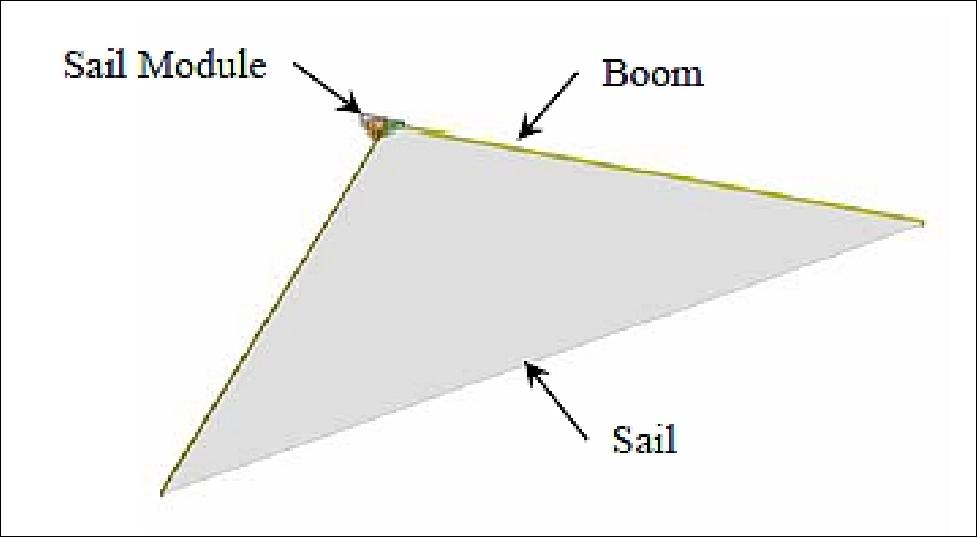
Module integration and shape: The modular approach to the design of the CanX-7 deorbiting payload allows for integration with any compatible spacecraft without substantially altering the existing bus design. In comparison, an integrated approach in which the drag sail components are housed by the existing bus structure would demand increased engineering effort beyond the scope of the mission for which the sail is designed. However, this choice means that opportunities for platform-specific optimization are traded for cross-platform compatibility.
The adoption of several modules, as opposed to a single module, creates more options for placement on irregularly shaped spacecraft. For integration with a cubesat bus, the modules are stacked atop one of the forward or aft square faces. Stacking the modules or covering them with solar panels eliminates the possibility of accessing their interior from the top or bottom face. This imposes a design constraint whereby the deployment mechanism and sail stowage solution must allow for access from the side panels for rewinding and repacking during testing of the fully-integrated spacecraft.
Integration with the other busses is more straightforward. For integration with a larger cube-shaped bus such as the Space Flight Laboratory's GNB, the modules are simply mounted on one of the exterior faces, and covered with a solar panel. On the NEMO bus the multi-module approach is particularly convenient, because it allows four modules (or more) to be mounted around the perimeter of a bus face, without requiring the whole face to be free of protrusions that might obstruct the sail's deployment.
The choice of a triangular sail module shape allows the booms to follow a straight path as they exit the module, which results in less resistance to tape motion than curved tape paths. The resulting footprint of the reel and straight tape paths lends itself to placing two triangular modules side-by-side to form a square, which conveniently matches the cross section of a CubeSat. Therefore, within the same volume both modules may be twice the height while using half the footprint of a square module. This height is used to accommodate ¾ inch-wide tape springs, which are sufficiently stiff to deploy the sail onto a smooth flat surface, and in certain orientations to support their own weight in a 1 g environment.
Deployment Mechanism: The CanX-7 payload works on the basic principle of stored mechanical energy. Stored mechanical energy is perceived to be more reliable than electrically driven deployment and require less capability from a spacecraft's power system, which may become unreliable or have diminished output at the end of its life.
The use of tape springs wound on a reel arose out of a desire to use COTS parts for simplicity and rapidity of prototyping. A reel is the natural shape for storing tape springs, and is used in similar deployable structures such as the Rolatube bistable reeled composite, lenticular cross section booms, TRAC boom, and STEM–derived booms. Conveniently, tape springs are capable of not only forming the stiff boom structure, but of providing the energy for their own deployment as well.
The use of the tape springs as the source of energy for deployment means that they must be stored in an enclosure that converts the uncoiling motion of the tape springs into linear motion of the booms. The sail module's circular tape enclosure serves this purpose, and is formed from rollers which exert little resistance against the rotational motion of the coiled tape springs.
The tapes are prevented from deploying by restraining them at the free ends that form the boom tips. This is accomplished by means of a door. The door will be opened by a torsion spring, and held closed by a pin that will positively prevent the door from opening due to vibration during launch. This "door release mechanism" will be disengaged to trigger deployment.
A piece of ground support equipment will serve as a separate "rewind mechanism" used to retract the booms into the sail module, when the interior of the module is inaccessible. The rewind mechanism will consist of an external rewind gear that will interface with a set of gear teeth located around the perimeter of the reel. A ratchet will prevent rotation of the external gear in the deployment direction.
Boom material and performance: Unlike a solar sail, a drag sail needs only to present frontal area in the ram direction without any need for the membrane to be made flat by holding it in tension. Therefore, the open section of tape-springs that otherwise makes them unsuitable for supporting longitudinal compression loads is acceptable for this application, in which they are loaded primarily in bending by the extremely small drag force. To ensure that the tape springs are loaded in a direction in which they resist bending loads, the booms are oriented such their convex side faces the sail. Each outboard corner of the triangular sail is attached to the boom tips by a pair of flexible lines that connect to the two corners of the boom section (Figure 27).
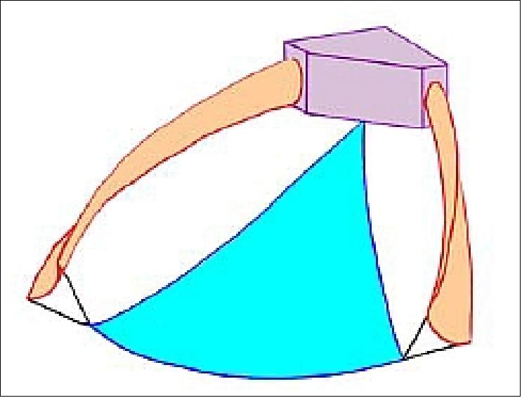
The magnitude of the drag load varies with the projected area of sail in the velocity direction. The greatest drag load occurs when the sail is face on to the velocity vector, as might occur when the spacecraft aero-stabilizes at lower altitudes. Under a drag load roughly perpendicular to the unloaded plane of the sail, the line closest to the direction in which the load is applied carries the majority of the sail tension, which imparts a moment to the boom tip that causes the entire boom to twist such that the concave side of the boom faces the direction of load application. On the ground, the result of this mounting arrangement is that the booms deform to a shape in which they are sufficiently strong to withstand the combined load of the sail's mass and the boom's mass. On orbit, the sail will be subjected to vastly smaller loads: At 300 km (the lowest altitude at which the sail is required to operate) the distributed drag force on each sail segment will be approximately 2 mN, which is more than 100 times less than mass of the sail film alone.
Sail Material and Stowage: The sail will be formed from metalized polymer film. Metalization is employed to protect the polymer from atomic oxygen and UV radiation. Ideally, the sail material would be transparent to eliminate disturbance torques from solar radiation pressure that, in polar sun synchronous orbits, serve to stabilize the sail into attitudes where it presents less area in the ram direction. However, resilient transparent polymer films (e.g., LaRC-CP1) are challenging to acquire due to export control laws. (Incidentally, metalized films of any kind thinner than 7.6 µm are difficult to acquire for the same reason.) Therefore, 12.7 µm thick Kapton film with a 300 Å aluminum coating on both sides will be employed as the sail material. Kapton is capable of withstanding the expected worst-case hot temperature of ~ 225ºC that the sail will reach in direct sunlight.
The sail module is required to be re-stowable without substantial disassembly or any de-integration from the spacecraft. Therefore, the sail is folded and packed into a separate sail cartridge that may be installed in the sail module, and removed after a deployment. The sail cartridge incorporates a door that serves the dual purpose of restraining the tightly packed sail material and restraining the spring-loaded boom tips. Compared to installing a loose sail bundle into an integrated sail module directly, installing a cartridge reduces the risk of damaging the sensitive solar cells and thermal coatings on the exterior of the spacecraft.
The sail is folded in an accordion or "Z" pattern in two perpendicular directions. The first direction is parallel to the outboard sail edge, and the second direction folds the resulting strip into a bundled shape that matches the irregular layout of the sail cartridge. The fold does not form enclosed volumes that could trap air, and is simple to re-fold, re-pack, and re-use.
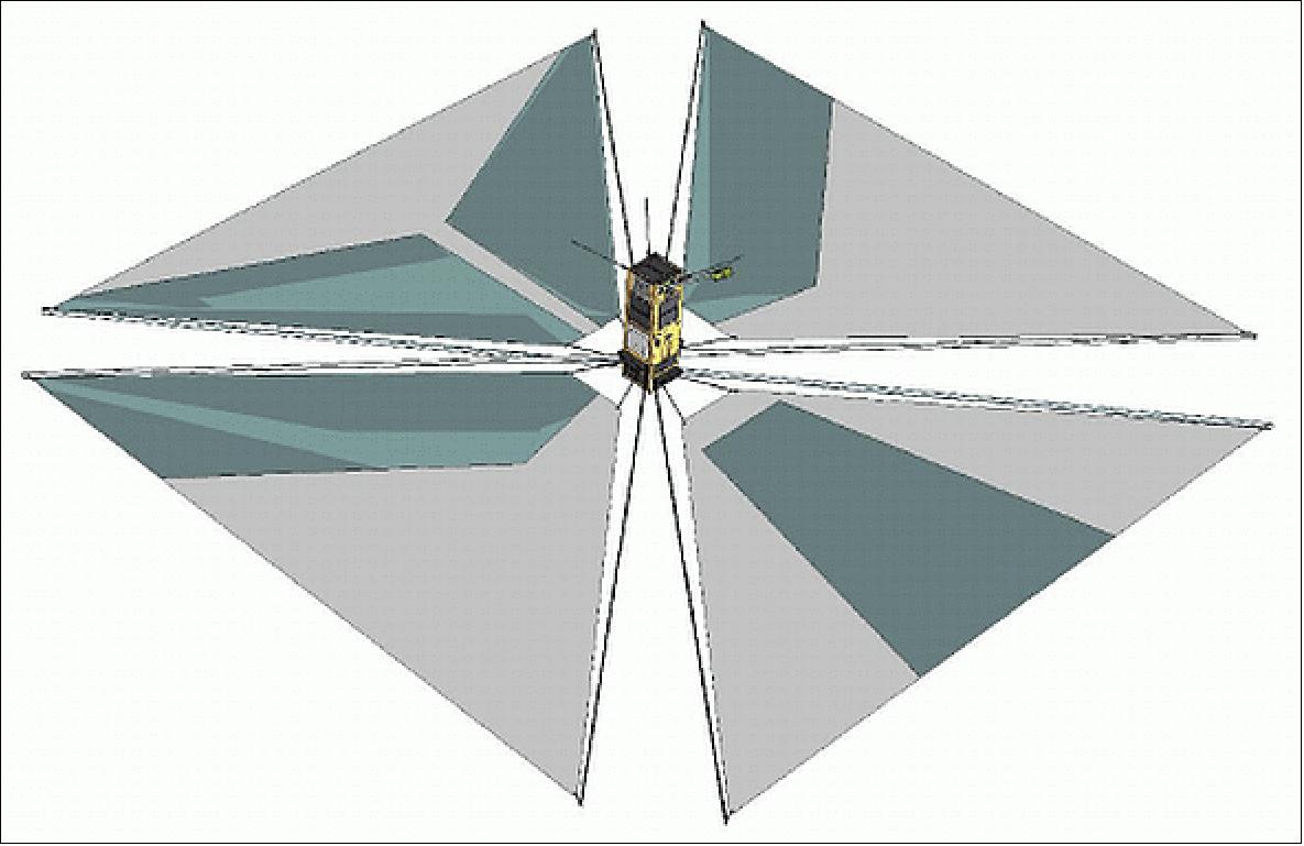
Drag Sail Inspection Camera: The telemetry gathered by the sail electronics can be used to fully infer deployment quality; however a more compelling way to verify deployment is with an image. Therefore, the miniature VGA Inspection Camera (mVIC) has been included as a tertiary payload on-board CanX-7. Not only can the inspection camera be used for evaluating drag sail deployment, but also for monitoring the drag sail for damage due to micrometeorite impacts during the deorbit lifetime. mVIC will be mounted on a deployable boom and uses three commercial off-the-shelf VGA resolution imagers optimally oriented in order to image all four sail sections. The FOV for each camera has been projected onto the sail sections to show the captured areas as seen in Figure 28. This same technology could be used on future missions for evaluating spacecraft health and providing deployment confirmation for drag sails, antennas, or solar arrays.
ADS-B (Automatic Dependent Surveillance - Broadcast)
CanX-7 will also accommodate a secondary ADS-B receiver payload being developed by COM DEV and RMCC (Royal Military College of Canada), Kingston, Canada. This secondary payload will be operated for six months following spacecraft commissioning, both in order to emulate an operational implementation of a deorbiting device (in which the drag sails are deployed once operations of a given payload cease), as well as to undertake potentially the first on-orbit demonstration of aircraft tracking from a nanosatellite. ADS-B signals are transmitted by aircraft in L-band (1090 MHz), and encode aircraft identity and position information derived from onboard navigation systems. Transmission power from aircraft ranges from 75 W to 500 W (49 dBm to 57 dBm), occurring at randomized intervals using PPM modulation (Ref. 5).
The continuing increase in commercial aviation traffic, combined with the inability of current radar surveillance to track aircraft beyond sight of land, have led to increasing interest in monitoring air traffic from space. When combined with other situational awareness techniques, spaceborne ADS-B monitoring can assist in flight planning over oceans and remote areas, which in turn would allow for decreased flight times, improved aircraft fuel economy, and reduced engine emissions.
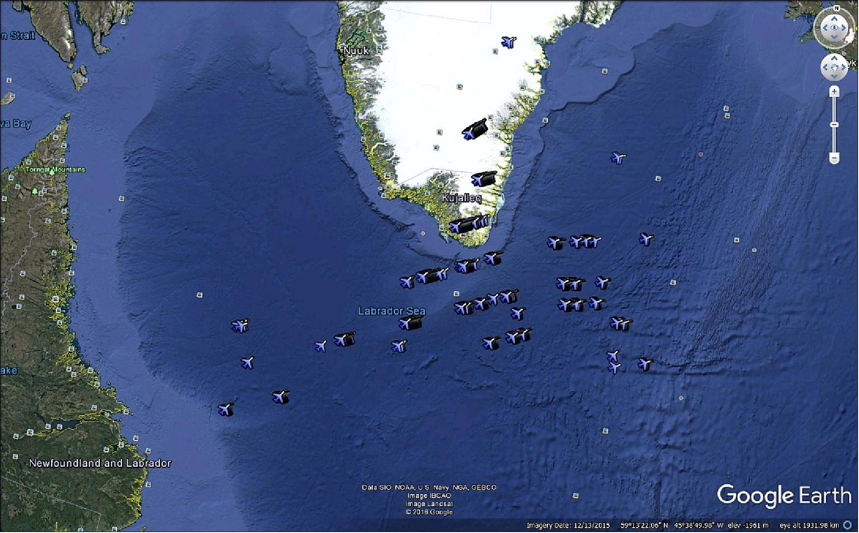
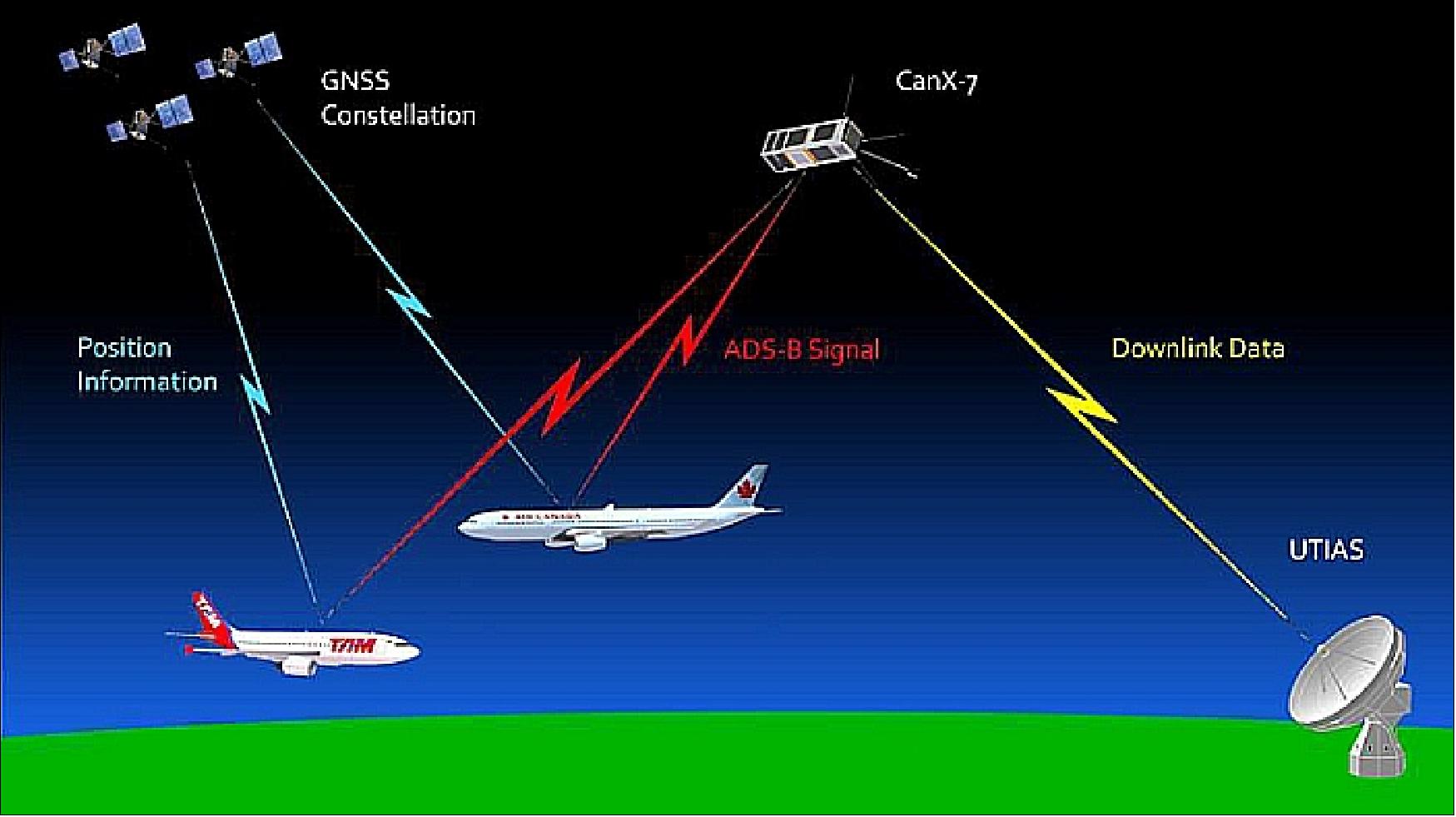
The concept of operations for the CanX-7 ADS-B payload is illustrated in Figure 29. Aircraft encode position, velocity, time and identity from on-board instruments and GPS satellites, and transmit ADS-B signals which are received by CanX-7 and transmitted to the CanX-7 ground station during next access. The ADS-B receiver for CanX-7 is illustrated in Figure 30.
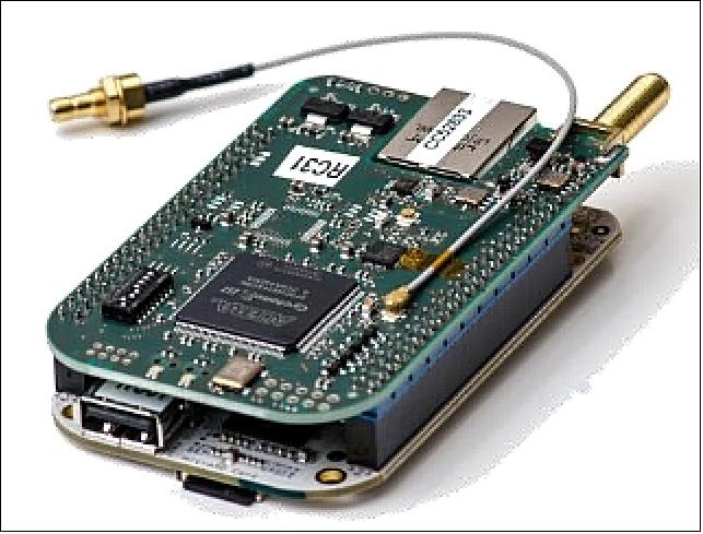
ADS-B is an air traffic surveillance technology in which aircraft routinely transmit aircraft identification, position, velocity and status during flight. Commercial air carriers use 1090 MHz to broadcast the 120-bit message at random periods between 0.4 and 0.6 seconds to prevent aircraft from having synchronized transmissions. The ADS-B signal alternates between top- and bottom-mounted quarter-wave monopole antennas, with transmitter power between 75 W and 500 W depending on the aircraft category . The transmissions can be received by other aircraft, or by ground stations for relay to ATS (Air Traffic Services) to provide timely and more accurate surveillance information than conventional surveillance radars. 23)
In recent years ADS-B has come into use in several regions to provide air traffic information where radar coverage is not available. Canada's ATS provider, NAV CANADA, has implemented ADS-B surveillance in the Hudson Bay corridor and Labrador regions, while airspace authorities in Europe, the United States, and Australia, have plans to implement ADS-B.
ADS-B coverage is currently limited by the placement of ground stations that cannot be installed in midocean and are difficult to maintain in Polar Regions. An orbital ADS-B system has the potential to provide precise aircraft surveillance in remote and oceanic airspace, which would transform existing traffic procedures that use standardized routes and large inter-aircraft spacing to provide separation. An operational spaceborne ADS-B system would reduce aircraft spacing requirements in oceanic regions leading to more efficient routes and subsequent reductions in fuel consumption. These efforts are topical with the announcement that ADS-B receivers are planned as secondary payloads on the Iridium NEXT constellation, a proposed 66-satellite LEO (Low Earth Orbit) constellation scheduled to be deployed by late 2017.
Each Iridium NEXT satellite will host an ADS-B receiver operated by Aireon LLC, making global near real-time tracking of aircraft possible for the first time. By using a micro-space design approach, similar performance and global coverage could be achieved by using a constellation of small satellites. The small satellite constellation approach could allow more countries to operate independent ATC (Air Traffic Control) systems, reduce operational costs, quicken deployment of new satellites, and make a global dataset of aircraft movements more readily accessible to a greater number of end users.
References
1) "Nanosatellites: CanX-7 Deorbiting Demonstration Mission," UTIAS/SFL, 2014, URL: http://utias-sfl.net/?page_id=210
2) Brad Cotten, Thomas M. C. Sears, Jesse Hiemstra, John Chung, Grant Bonin, Robert E. Zee, "The Canx‐7 Nanosatellite Deorbit Mission: Demonstrating Sustainable Use of Low‐Earth Orbit," Proceedings of the 4S (Small Satellites Systems and Services) Symposium, Port Petro, Majorca Island, Spain, May 26-30, 2014
3) Vincent Tarantini, Grant Bonin, Robert Zee, "Deorbit analysis of tumbling sailcraft," Proceedings of the 4S (Small Satellites Systems and Services) Symposium, Port Petro, Majorca Island, Spain, May 26-30, 2014
4) Barbara Shmuel, "Canadian Advanced Nanospace EXperiment 7 (CanX-7) Mission Analysis, Payload Design and testing," Thesis submitted for the degree of Master of Applied Science, UTIAS, University of Toronto, 2012, URL: https://tspace.library.utoronto.ca/bitstream/1807/33526/1/Shmuel_Barbara_201211_MASc_thesis.pdf
5) Grant Bonin, Jesse Hiemstra, Thomas Sears, Robert E. Zee, "The CanX-7 Drag Sail Demonstration Mission: Enabling Environmental Stewardship for Nano- and Microsatellites," Proceedings of the 27th AIAA/USU Conference, Small Satellite Constellations, Logan, Utah, USA, Aug. 10-15, 2013, paper: SSC13-XI-9, URL: http://digitalcommons.usu.edu/cgi/viewcontent.cgi?article=2993&context=smallsat
6) Thomas M. C. Sears, Brad Cotten, Grant Bonin, Robert E. Zee, "Performance Analysis of Thin Film Materials for Application in a Drag Sail De‐orbiting Device," Proceedings of the 4S (Small Satellites Systems and Services) Symposium, Port Petro, Majorca Island, Spain, May 26-30, 2014
7) Barbara Shmuel, Jesse Hiemstra, Vincent Tarantini, Fiona Singarayar, Grant Bonin, Robert E. Zee, "The Canadian Advanced Nanospace eXperiment 7 (CanX-7) Demonstration Mission: Deorbiting Nano- and Microspacecraft," Proceedings of the 26th Annual AIAA/USU Conference on Small Satellites, Logan, Utah, USA, August 13-16, 2012, paper: SSC12-I-9, URL: http://digitalcommons.usu.edu/cgi/viewcontent.cgi?article=1022&context=smallsat
8) Fiona Singarayar, "Preliminary Development and Detailed Structural Design and Analysis for the CanX-7 Nanosatellite," Thesis submitted for the degree of Master of Applied Science, UTIAS, University of Toronto, 2012, URL: https://tspace.library.utoronto.ca/bitstream/1807/33531/1/Singarayar_Fiona_201211_MASc_Thesis.pdf
9) Jesse Hiemstra, Barbara Shmuel, Fiona Singarayar, Vincent Tarantini, Brad Cotten, Bryan Johnston-Lemke, Grant Bonin, Robert E. Zee, "The CanX-7 Drag Sail Mission - A cubesat for demonstrating a small-satellite compatible deorbiting device," 2012 Summer CubeSat Developers' Workshop, Logan, Utah, USA, Aug. 11-12, 2012, URL: http://mstl.atl.calpoly.edu/~workshop/archive/2012/Summer/Day%201/1315-Hiemstra-CanX7DragSailMission.pdf
10) Barbara Shmuel, Fiona Singarayar, Grant Bonin, Dr. Robert E. Zee, "CanX‐7: A Canadian Demonstration Mission for Deorbiting Nano‐ and Microspacecraft," ASTRO'12 16th ACSI Astronautics Conference, Québec City, Canada, April 23-26, 2012
11) "PSLV-C35 / SCATSAT-1, ISRO, Sept. 26, 2016, URL: http://www.isro.gov.in/launcher/pslv-c35-scatsat-1
12) "PISAT nanosatellite ready for space launch in July 2016," PES News, April 20, 2016, URL: http://news.pes.edu/pisat-nanosatellite-ready-for-space-launch-in-july-2016/
13) "Space Flight Laboratory Announces Successful Deorbiting of Nanosatellite with Drag Sail Technology. Sails Reduced Time as Space Debris by 178 Years," UTIAS/SFL 13 June 2022, URL: https://www.utias-sfl.net/?p=3942
14) Brad Cotten, Ian Bennett, Robert E. Zee, "On-Orbit Results from the CanX-7 Drag Sail Deorbit Mission," Proceedings of the 31st Annual AIAA/USU Conference on Small Satellites, Logan UT, USA, Aug. 5-10, 2017, paper: SSC17-X-06, URL: http://digitalcommons.usu.edu/cgi/viewcontent.cgi?article=3672&context=smallsat
15) V. Tarantini, G. Bonin and R. E. Zee, "De-Orbit Analysis of a Tumbling Sailcraft," Proceedings of the Small Satellites Systems and Services Symposium, Porto Perto, 2014
16) "After Only One Week, CanX-7 Shows Drag Sails are Effective at Deorbiting Satellite," UTIAS/SFL, May 11, 2017, URL: https://web.archive.org/web/20221201072141/https://www.utias-sfl.net/?p=2649
17) "CanX-7 Successfully Deploys Drag Sails kicking off Deorbiting Demonstration," UTIAS/SFL, May 4, 2017, URL: https://web.archive.org/web/20221201061044/https://www.utias-sfl.net/?p=2644
18) "Smallsat Dragging Its Sails on Demo Mission," Satnews Daily, May 8, 2017, URL: http://www.satnews.com/story.php?number=1038715858
19) Ian Bennett, Brad Cotten, Robert E. Zee, "On-orbit results from the CanX-7 ADS-B payload," Proceedings of the 11th IAA Symposium on Small Satellites for Earth Observation, Berlin, Germany, April 24-28, 2017, paper: IAA-B11-0804
20) Information provided by Daniel D. Kekez, Senior Missions Engineer at UTIAS/SFL.
21) CanX-7 Satellite Mission," RMCC (Royal Military College of Canada), Oct. 4, 2016, URL: https://www.rmcc-cmrc.ca/en/physics/canx-7-satellite-mission
22) "CanX-7 Aircraft Tracking and Deorbiting Demo Satellite Launched, Contacted, and Healthy," UTIAS/SFL, Sept. 26, 2016, URL: https://web.archive.org/web/20221201075627/http://www.utias-sfl.net/?p=2516
23) Richard Van Der Pryt, Ron Vincent, "A Simulation of Reflected ADS-B Signals over the North Atlantic for a Spaceborne Receiver," published online 25 February 2016 in SciRes (Scientific Research Publishing), URL: http://www.scirp.org/journal/PaperDownload.aspx?DOI=10.4236/pos.2016.71005
The information compiled and edited in this article was provided by Herbert J. Kramer from his documentation of: "Observation of the Earth and Its Environment: Survey of Missions and Sensors" (Springer Verlag) as well as many other sources after the publication of the 4th edition in 2002. - Comments and corrections to this article are always welcome for further updates (eoportal@symbios.space).
Spacecraft Launch Mission Status Experiments References Back to Top