Clementine Lunar Mission
Non-EO
Exploration
Quick facts
Overview
| Mission type | Non-EO |
| Launch date | 25 Apr 1994 |
Clementine Lunar Mission
Clementine was a lunar mission of the US DoD (Department of Defence), a joint project between BMDO (Ballistic Missile Defense Organization) and NASA. The objective was to demonstrate new technologies, in particular sensors and spacecraft components under extended exposure to the space environment and to make scientific observations of the moon and the near-Earth asteroid 1620 Geographos. By implementing the ”faster, cheaper, better” management approach, Clementine was able to move from conceptual design to launch in only 22 months.
The observations included imaging at various wavelengths including ultraviolet and infrared, laser ranging altimetry, and charged particle measurements. These observations were originally for the purposes of assessing the surface mineralogy of the Moon and Geographos, obtaining lunar surface altimetry from latitudes of ±60º, and determining the size, shape, rotational characteristics, surface properties, and cratering statistics of Geographos. The Clementine technology demonstration mission is also known as DSPSE (Deep Space Program Science Experiment). 1) 2) 3) 4) 5) 6) 7) 8) 9) 10)
Spacecraft
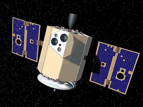
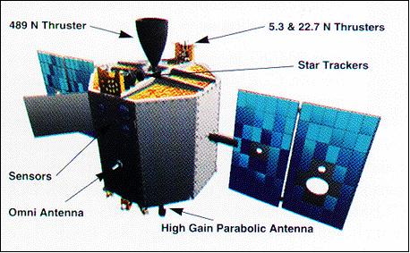
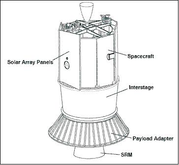
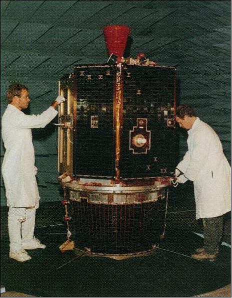
The Clementine spacecraft was designed, built, integrated and operated at the US Naval Research Laboratory (NRL) in Washington, DC. The lightweight S/C structure was an octagonal prism (provided by the USAF), 1.88 m in height and 1.14 m in diameter with two solar panels protruding on opposite sides, parallel to the axis of the prism. A high-gain fixed dish antenna was at one end of the prism, and the 489 N thruster at the other end. The sensor openings were all located together on one of the eight panels, 90º from the solar panels, and protected in flight by a single sensor cover. The spacecraft propulsion system consisted of a non-propellant hydrazine system for attitude control and a bipropellant nitrogen tetraoxide and monomethyl hydrazine system for the maneuvers in space. The bipropellant system had a total ΔV capability of about 1900 m/s with about 550 m/s required for lunar insertion and 540 m/s for lunar departure.
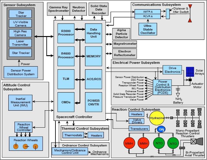
Attitude control was achieved with 12 small attitude control jets, two star tracker cameras, and two inertial measurement units. The spacecraft was three-axis stabilized in lunar orbit via reaction wheels with a precision of 0.05º in control and 0.03º in pointing knowledge. Power was provided by gimbaled, single axis, GaAs/Ge solar panels which charged a 15 Ahr, 47 Whr/kg Nihau (Ni-H) common pressure vessel battery. By rolling the spacecraft and rotating the panels, full solar illumination of the panels was achieved.
Spacecraft data processing was performed using a MIL-STD-1750A computer (1.7 million instructions/s) for save-mode, attitude control, and housekeeping operations, a RISC 32 bit processor (18 MIPS) for image processing and autonomous operations, and an image compression system provided by CNES, the French Space Agency. A data handling unit sequenced the cameras, operated the image compression system, and directed the data flow. Data was stored in a 2 Gbit dynamic solid state data recorder.
The total launch mass of the spacecraft was 1690 kg, with most of the weight in the solid rocket motor required for translunar insertion. The spacecraft dry mass was 227 kg, and 424 kg with propellant.
RF Communications
Data transmission in S-band at data rates of 0.125 - 128 kbit/s (selectable), uplink at 1 kbit/s. Telemetry support was provided by the DSN (Deep Space Network) of NASA and the NRL tracking station in Pomonkey, MD (NRL mission control center in Alexandria, VA).
Structures | - Conventional (Aluminum) longerons with honeycomb skins |
ACS (Attitude Control Subsystem) | - Three-axis stabilized for all modes except for spin stabilized TTI burn |
EPS (Electric Power Subsystem) | - Gimbaled (single-axis) GaAs/Ge solar cells, |
Propulsion | - SRM (Solid Rocket Motor) auxiliary kick motor STAR 37FM |
CT&DH (Command, Telemetry & Data Handling) | - Primary controller: MIL-STD-1750A radiation-hardened processor |
Communication subsystem | - S-band transponder, downlink rates: 125 bit/s to 128 kbit/s, uplink: 1 kbit/s |
Thermal design | Combined active and passive thermal design |
S/C mass | 424 kg (with propellant), 227 kg dry mass |
S/C size | 1.14 m diameter x 1.88 m |
Launch
A launch of Clementine took place on April 25, 1994 on a Titan-2G ELV (Expendable Launch Vehicle) from VAFB, CA. The launch was provided by the USAF.
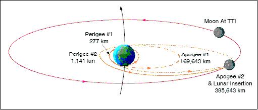
Orbit: Lunar transfer orbit after two Earth flybys. [a ΔV was executed i.e., a TTI (Translunar Transfer Injection) that placed Clementine into a lunar phasing loop orbit with two Earth flybys].
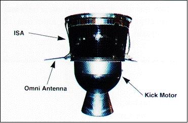
The STAR 37FM kick motor (SRM) and ISA, collectively referred to as the ISAS (Interstage Adapter Subsystem), separated from the spacecraft during this phasing orbit. The ISAS remained in a highly elliptical orbit (6,700 km x 133,000 km, inclination of 66º) for several months to collect and to telemeter to Earth radiation data from the Van Allen belts.
Clementine performed a ΔV maneuver using its bipropellant propulsion system to inject into a higher phasing loop orbit that intersected the moon on February 19, 1994. Lunar insertion was achieved on February 21, 1994.
• Lunar orbit: semimajor axis = 5,116.0 km, eccentricity = 0.36, inclination = 90º, apoapsis = 4,594 km, periapsis = 2,162 km, orbital period = 300 minutes.
• Once in lunar orbit, Clementine began its primary 71 day mapping mission.
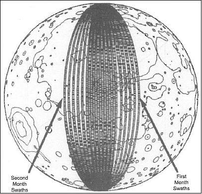
• The first part of the lunar observations consisted of a 5 hour elliptical polar orbit with a perilune of about 400 km at 28º S latitude (400 km x 1225 km).
• After one month of mapping, the orbit was rotated to a perilune of 29º N latitude, where it remained for one more month. This allowed global imaging as well as altimetry coverage within the latitudes of ±60º.
Mission Status
The science data returned by Clementine (~ 330 Gbit total) has revolutionized our knowledge and appreciation of lunar history and evolution. Clementine gathered a data set still actively studied by the science community and yielding new insights into lunar processes and history. The discovery of the unique environments of the lunar poles, and the probable discovery of water ice in the dark regions there are findings of enormous significance to humanity's future on the Moon and in space in general. Clementine demonstrated that fast-track, new technology missions can be scientifically productive (Ref. 12).
The Clementine mission was very successful in terms of space-qualifying 23 advanced, lightweight technologies during its life. Clementine contributed significantly to lunar studies by taking 1.8 million images of the surface of the moon (mapping of 38 x 106 km2). In addition, the LIDAR instrument returned lunar topography information, and analysis of the fine details of Clementine's orbit revealed details about the moon's gravitational field. Its failure to completely meet all of its secondary science goals does not appear to have been due to any deficiency in the advanced technology used. Moreover, the significant deep-space capabilities demonstrated within the payload capacity of a relatively small launch vehicle were, in fact, enabled by the lightweight/high-performance technologies used.
The following are major events of the mission:
• Feb. 3, 1994: Departure from low Earth orbit following eight day checkout period
• Feb. 19, 1994: Following two phasing orbits Clementine injected into lunar orbit
• Feb 26, 1994: Start of systematic mapping of the moon
• Mar. 24, 1994: First mapping pass nearly complete
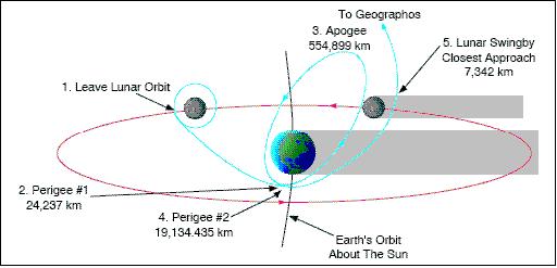
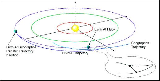
• May 5, 1994: After successfully completing the imaging mission - the lunar orbit was left (ΔV maneuver) with the objective to rendezvous with the asteroid 1620 Geographos in June 1994. Clementine entered a highly elliptical Earth orbit - and was to have used a gravity-assisted lunar swingby to enter a new trajectory and flyby the near-Earth asteroid Geographos about eight months after launch (Figure 8).
• May 7, 1994: A malfunction occurred in one of the onboard computers which controls most of the satellite's systems including the attitude control thrusters, causing a thruster to fire prematurely until it had used up all of its fuel, leaving the spacecraft spinning at about 80 rpm with no spin control. This prevented Clementine from performing the planned close flyby on the near-Earth asteroid Geographos (Figure 9).
• In June 1994, the signals from the spacecraft became so weak that no more data from the mission could be received. However, mission controllers were able to reestablish contact with the Clementine spacecraft in February 1995.
Sensor/Experiment Complement
The Lawrence Livermore National Laboratory (LLNL) was responsible for the onboard instrumentation providing advanced lightweight imaging sensor technology developed under the sponsorship of BMDO. 11)
The lunar mapping science objective was to obtain topographic imaging, altimetry data, and multispectral imaging of the lunar surface. The topographic imaging and altimetry data were to be obtained for as much of the moon's surface as possible; but due to the limitations of the HIRES camera and the laser ranger, 100% coverage was not possible.
The Clementine mission mapped the moon from February 19 to May 3, 1994 - producing the first multispectral global digital map of the Moon, the first global topographic map, and contributing several other important scientific discoveries, including the possibility of ice at the lunar south pole. 12)
UV/VIS Camera (Ultraviolet/Visible Camera)
The objective was to study the surfaces of the mon and the asteroid Geographos at five different wavelengths in the ultraviolet and visible spectrum. The camera had a filter wheel with six different filters, ranging from 415 nm to 1000 nm, and included a broad-band filter covering 400 to 950 nm.
The lightweight UV/VIS camera (0.41 kg, 4.5 W of average power) was designed for inexpensive manufacture, test, and calibration. The optics, filter wheel, and camera assembly were modular. The FPA (Focal Plane Array) was a phosphor-coated silicon CCD (Charged Coupled Device). The CCD array was 384 x 288 in size with a pixel size of 23 µm x 23 µm. The optics consist of a catadioptric SiO2 glass with 46 mm aperture and a speed of f/1.96. The imaging FOV (Field of View) was 4.2º x 5.6º. The UV/VIS camera electronics operated at a maximum frame rate of 30 Hz with an 8 bit ADC (Analog to Digital Converter). Filter wheel center wavelength positions: A: 415 nm (40 nm width), B: 750 nm (10 nm), C: 900 (20 nm), D: 950 nm (30 nm), E: 1000 nm (30), F: broadband. The FOV translated to a cross-track width of about 40 km at a nominal 400 km lunar altitude.
NIR (Near Infrared) Camera
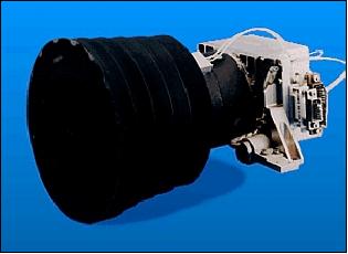
NIR is with a total mass of 1.92 kg (including the Stirling-cycle cryocooler), a size of 11.5 cm x 12 cm x 37 cm, and average power of 11 W. NIR had also a six-filter wheel, observing in the spectral range from 1070 nm to 2840 nm (SWIR). The filter center wavelengths [and bandpass widths (FWHM)] were at: 1100 nm (60 nm), 1250 nm (60 nm), 1500 nm (60 nm), 2000 nm (60 nm), 2600 nm (60 nm), and 2780 nm (120 nm). Use of an InSb detector array in the focal plane with a pixel format of 256 x 256 pixels. The detector was mechanically cooled to 70 K. FOV of 5.6º x 5.6º (40 km cross-track 400 km altitude) with an IFOV of 396 µrad. The spatial resolution varied from 150-500 m during a single lunar orbit. The camera took twelve images in each 1.3 s image burst, which occurred 75 times over the 80 minute mapping span during each lunar orbit.
LWIR (Long-Wave Infrared) Camera
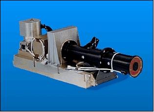
LWIR is with a total mass of 2.1 kg (including the Stirling-cycle cryocooler) and 13 W of average power. The camera used a catadioptric lens with an aperture of 131 mm. The FPA had a broadband response in the spectral range of 8-9.5 µm. The camera used a HgCdTe detector array of 128 x 128 pixels which was mechanically cooled to 65 K. FOV of 1º x 1º with an IFOV of of 143 µrad (this configuration translated to a width of about 17.5 km at 1000 km distance).
At the moon, the camera was used primarily for nightside imaging near the poles, where it could take 660 images over a ten minute pass each five hour orbit. It was also used for selected high-resolution images in other areas. The camera imaged approximately 0.4% of the moon's surface (both poles from 85º - 90º) over the two month lunar phase of the mission. The nominal signal-to-noise ratio (SNR) was 950, with a relative calibration of 1% and an absolute calibration of 30%, and a gain ranging from 0.5 to 36.
HIRES (High Resolution Camera)
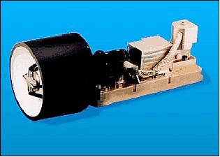
HIRES is with a total mass of 1.12 kg, a size of 17 cm x 18 cm x 36.5 cm, and average power of 10 W. HIRES consisted of a telescope with an image intensifier and a frame-transfer CCD imager. Study of selected portions of the moon surface. Observations were conducted in the visible spectral range. The passbands were defined by a six-position filter wheel: 395 - 435 nm, 535 - 585 nm, 625 - 675 nm, 725 - 775 nm, and 450 - 800 nm, with an opaque disc in the sixth position to protect the intensifier. FOV of 0.3º x 0.4º; a silicon CCD in the focal plane with a pixel format of 384 x 288. HIRES provided high-resolution imagery (spatial resolution of about 2 km at 400 km altitude) free of spacecraft motion blur.
The telescope of HIRES was shared by the LIDAR instrument. The 1064 nm laser return was split to the LIDAR receiver (an avalanche photodiode detector) using a dichroic filter.
STC (Star Tracker Camera)
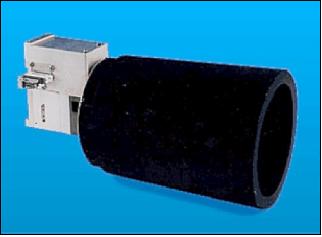
STC is with a mass of 0.290 kg, a size of 12 cm x 12 cm x 14 cm, and power of 4.5 W. Two cameras were flown and used primarily for attitude determination, although it was also used to collect scientific data. STC used silicon CCD technology with a 384 x 576 pixel array sensitive between 0.4 - 1.1 µm. It had a wide FOV of 29º x 43º, to make more stars available for attitude determination. Its instantaneous field of view (IFOV) was 1.3 mrad.
An image from a startracker was processed aboard the spacecraft using a computer program, Stellar Compass, provided by LLNL. Stellar Compass compared the angular relationships of stars in a startracker image to those provided by a stored star catalog of 600 stars distributed over the celestial sphere. Stellar Compass and the star catalog were resident in the R3081 RISC processor. Typically attitude determination could be made within 100 ms using a single startracker image. An attitude determination of medium accuracy was provided (≤ 150 µrad in pitch and yaw and 450 µrad in roll).
LIDAR (Laser Image Detection and Ranging) System
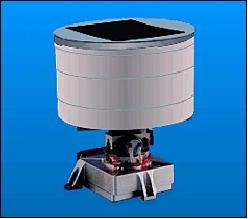
The LIDAR laser transmitter and power supply had a total mass of 1.25 kg and were very compact ( average power of 6.8 W). The instrument was successfully used for lunar altimetry observations. The transmitter was a diode-pumped Nd:YAG laser emitting at 1064 nm with 180 mJ per pulse and a pulse duration of 10 ns. The transmitter ran continuously at a 1 Hz pulse rate with short bursts at 8 Hz limited by thermal effects. The receiver for the laser ranger was an avalanche photodiode within the HIRES camera and shared its optics. Range measurements could be made to a maximum of 640 km, with a radial resolution of 40 m (footprint of about 100 m). The 1 Hz pulse provided an along-track spacing of 1-2 km.
CPT (Charged Particle Telescope)
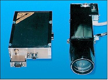
The primary goals of the investigation were to: 1) study the interaction of the Earth's magnetotail and interplanetary shocks with the moon; 2) monitor the solar wind in regions far removed from other spacecraft as part of a multimission coordinated study; and 3) measure the effects of incident particles on the operating ability of the spacecraft solar cells and other sensors.
To meet the stringent limit on the mass of the instrument (< 1 kg), it was implemented as a single element telescope. The telescope had a half-angle FOV of 10º. The detector, a silicon surface-barrier type with an area of 100 mm2 and a thickness of 3 mm, was shielded so as to prevent protons below 30 MeV from reaching it from directions other than via the aperture. The aperture was covered by a very thin foil to prevent light impinging on the detector and generating noise. The signal from the detector was split into nine channels, the lowest six dedicated to electron detection and the highest three to protons and heavier ions.
Gravity Experiment
The gravity experiment used measurements of perturbations in the motion of the spacecraft to infer the lunar gravity field. Clementine was equipped with an S-band microwave transponder and two S-band omni-directional high-rate antennas. The frequency of the S-band transmission was measured every 10 seconds, and the Doppler shift provided the relative velocity of the spacecraft towards or away from the Earth. Accelerations were calculated from changes in the velocity, and after accounting for the orbit, relative motions of Earth and moon, and Earth and solar gravity, these accelerations are converted to lunar gravity effects on the spacecraft. The calculated lunar gravity field can be used to model subsurface lunar structure. The Pomonkey station was able to measure the velocity to an accuracy of 3 mm/s, while the DSN stations could achieve about 0.3 mm/s. 13)
Tracking was not possible on most of the lunar far side (120º - 240º in longitude and ±45º in latitude), when the moon was between the spacecraft and the Earth. In all, over 361,000 observations were made, approximately 57,000 at less than 1000 km altitude.
Bistatic Radar Experiment
Although Clementine did not carry any instrument specifically designed to look into the shadow regions of the moon, a simple radio mapping experiment was improvised in real-time during the mission to test the hypothesis that water ice deposits might exist in these areas. As Clementine shifted its periselene from 30º N for the second month of mapping, the spacecraft antenna was pointed directly at the pole of the moon, beaming continuous wave RF into the polar areas (Figure 17). During this time, the DSN 70 m dish received the echoes, in two polarization channels. Ice and dirt have distinct RF scattering properties; specifically, ice is partly transparent to RF, resulting in absorption and multiple scattering. The net effect of the presence of ice is to reflect some RF back in the sense of polarization as was transmitted (Ref. 12).
This experiment made use of the radio transmitting equipment aboard Clementine to search the moon's polar regions for evidence of ice in permanently shadowed craters. The basic method of bistatic radar involves a spacecraft transmitting a radio signal at a point on the target body. Reflections of these signals from the target are received on Earth. The properties of the received reflections can be interpreted to give information on the target surface. 14)
In this configuration, Clementine transmitted an unmodulated S-band right-circularly polarized signal (RCP) through the 1.1 m high-gain antenna which was aimed at the polar regions of the moon for radar scattering experiments (in particular the deep Shackleton crater at the lunar south pole was of great interest). The signal had a frequency of 2.273 GHz (13.19 cm wavelength), and a net power of about 6 W. The high gain antenna has a half-power half-beamwidth of 4.0º. Reflections were received on Earth by the 70 m antennas of the DSN at Goldstone (United States), Madrid (Spain) and Canberra (Australia). During these passes, the lunar axial tilt toward Earth at the DSN stations was 4.5º to 5.5º. The experiment can be done when the target and DSN receiver are coplanar with the spacecraft orbital plane. The bistatic radar experiment was performed for the lunar south pole during orbits 234, 235, 236, and 237 on April 9-10, 1994 (received at Goldstone, Madrid, and Canberra). Observations of the north pole were made on orbits 299, 301, and 302 on 23 and 24 April 1994 (received at Madrid and Canberra). However, systematic errors made the results from orbits 236, 237, and 299 unusable.

ISAS (Interstage Adaptor Satellite)
The Clementine ISAS (Interstage Adapter Satellite) was the lunar transfer booster used to propel the Clementine spacecraft to the Moon from Earth orbit.
After ISAS separated from the Clementine spacecraft, it assumed an Earth orbit with an inclination of 66º, an eccentricity of 0.90, and a period of 52 hours. The initial apogee was 133,370 km and the initial perigee was 6736 km. This highly eccentric orbit meant that the ISAS spent less than one hour in LEO each orbit. Thus most of the exposure was to a relatively debris-free environment. The OMDC (Orbital Meteoroid and Debris Counter) experiment was flown on the ISAS. 15) 16) 17)
The OMDC was comprised of 48 MOS microparticle impact detectors arranged in three groups of 16, distributed circumferentially around the periphery of the ISAS. Each group occupied a 120º arc of the circumference of the ISAS, just below the top ring. The OMDC sensors were designed to detect hypervelocity impacts of microparticles of 0.5 µm diameter and larger.
The ISAS DAS (Data Acquisition System) sampled the value of the OMDC counters once every five seconds. If any counter value was found to differ from its previous value, the values of all three counters were stored in the DAS buffer memory. Twice per hour the DAS read the total OMDC sensor bias current into the buffer memory, along with other analog data. Housekeeping data and the data from several other experiments was also stored in the buffer memory. ISAS data downlinks were possible near the time of perigee passage (~52 hr periods) when the spacecraft was within 20,000 km of a ground station..
Neglecting five turn-on events, a total of 75 impacts were recorded. Fifty-three of these events were time-tagged, allowing a determination of the spacecraft location at impact. The data divide cleanly into two periods; 22 impacts were recorded during the first 76, while 53 impacts were recorded in the last 19 days. Only one-third of the early impacts were time-tagged; seven of these occurred within ten degrees of apogee. Almost all of the remaining impacts were time tagged and were distributed relatively uniformly around the orbit. No impacts were observed at altitudes of less than 2000 km.
For 95 days, from early February to early May, 1994, ISAS carried the OMDC (Orbital Meteoroid and Debris Counter) experiment in its eccentric Earth orbit.
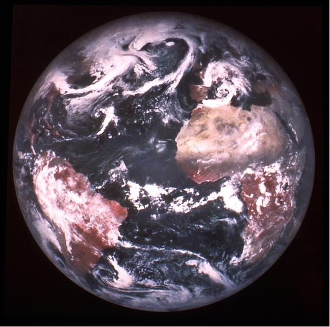
Legend to Figure 18: This image is a mosaic of color, high-resolution frames. Africa is clearly visible on the right and South America is visible on the left. This is a “false-color” version that makes vegetation appear red.
References
1) “The Clementine Mission,” URL: http://www.cmf.nrl.navy.mil/clementine/
2) “Missions to the Moon,” URL: http://www.planetary.org/explore/topics/our_solar_system/the_moon/missions.html
3) “Clementine Project Information,” URL: http://nssdc.gsfc.nasa.gov/planetary/clementine.html
4) S. Nozette, P. Rustan, L. P. Pleasance, D. M. Horan, P. Regeon, E. M. Shoemaker, P. D. Spudis, C. H. Acton, D. N. Baker, J. E. Blamont, B. J. Buratti, M. P. Corson, M. E. Davies, T. C. Duxbury, E. M. Eliason, B. M. Jakosky, J. F. Kordas, I. T. Lewis, C. L. Lichtenberg, P. G. Lucey, E. Malaret, M. A. Massie, J. H. Resnick, C. J. Rollins, H. S. Park, A.. S. McEwen, R. E. Priest, C. M. Pieters, R. A. Reisse, M. S. Robinson, R. A. Simpson, D. E. Smith, T. C. Sorenson, R. W. Vorder Breugge, M. T. Zuber, “The Clementine mission to the Moon: Scientific overview,” Science, Vol. 266, No. 5192, Dec. 1994, pp. 1835-1839, URL: http://www.planetary.brown.edu/pdfs/1662.pdf
5) T. C. Sorensen, P. D. Spudis, “The Clementine mission - A 10-year perspective,” Journal of Earth System Science, Vol. 114, No. 6, Dec. 2005., pp. 645-668, URL: http://www.spudislunarresources.com/Bibliography/p/86.pdf
6) Paul D. Spudis and D. Ben J. Bussey, “Clementine Explores the Moon,” URL: http://www.lpi.usra.edu/resources/clemen/clemen.html
7) http://www.lpi.usra.edu/expmoon/clementine/clementine.html
8) P. A. Regeon, R. J. Chapman, R. Baugh, “Clementine - The Deep Space Program Science Experiment,” IAA (International Academy of Astronautics) Conference, Laurel, MD, USA, Apr. 12-15, 1994, IAA-L-0501
9) P. A. Regeon, R. J. Chapman, R. Baugh, “Clementine - The Deep Space Program Science Experiment,” Engineering and Technology Workshop, Lake Tahoe, NV, USA, July 18-19, 1994
10) S. Nozette, R. J. Chapman, P. A. Regeon, P. Lynn, D. Bakeris, “Application of Clementine Technology to Future Lunar Exploration,” European Geophysical Society, Hamburg, Germany, April 3-7, 1995, URL: http://www.docstoc.com/docs/15521007/APPLICA...
11) “Clementine Experiments and Data at NSSDC,” 2004, URL: http://nssdc.gsfc.nasa.gov/planetary/clemendata.html
12) Trevor C. Sorensen, Paul D. Spudis, “The Clementine mission - A 10- year perspective,” Journal of Earth System Science, Vol. 114, No 6, Dec. 2005, pp. 645-668, URL: http://www.spudislunarresources.com/Bibliography/p/86.pdf
13) “Clementine S-Band Transponder Doppler Gravity Experiment,” URL: http://nssdc.gsfc.nasa.gov/nmc/masterCatalog.do?sc=1994-004A&ex=08
14) S. Nozette, C. L. Lichtenberg, P. Spudis, R. Bonner, W. Ort, E. Malaret, M. Robinson, E. Shoemaker, “The Clementine Bistatic Radar Experiment,” Science, Vol. 274, Nov. 29, 1996, pp: 1495-1498, URL: http://www.spudislunarresources.com/Bibliography/p/59.pdf
15) http://setas-www.larc.nasa.gov/CLEM/TAH_JPO.HTML
16) http://setas-www.larc.nasa.gov/CLEM/whk_pub.html
17) W. H. Kinard, ”Orbiting Meteoroids and Debris Counting Experiment”, Clementine Engineering and Technology Workshop, Lake Tahoe, July 18-19, 1994
The information compiled and edited in this article was provided by Herbert J. Kramer from his documentation of: ”Observation of the Earth and Its Environment: Survey of Missions and Sensors” (Springer Verlag) as well as many other sources after the publication of the 4th edition in 2002. - Comments and corrections to this article are always welcome for further updates (eoportal@symbios.space)