CuPID (Cusp Plasma Imaging Detector)
Non-EO
Space Weather
Science
Quick facts
Overview
| Mission type | Non-EO |
| Launch date | 27 Sep 2021 |
CuPID (Cusp Plasma Imaging Detector) Mission
Science Objectives Spacecraft Launch Sensor Complement Ground Segment References
CuPID is a 6U CubeSat science mission designed to answer fundamental questions in plasma physics and space weather. The project is a collaboration between Boston University, Drexel University, NASA Goddard Space Flight Center, Johns Hopkins University, Merrimack College, Adcole Maryland Aerospace, Aerospace Corporation, and the University of Alaska at Fairbanks. The mission is supported by NASA and is scheduled to launch in September 2021 on the Landsat-9 mission a joint project of NASA and USGS (United States Geological Survey). 1) 2)
The objective of CuPID is to study macroscale properties of dayside magnetopause reconnection. Reconnection will be studied through imaging spatial and temporal ion dispersion signatures in the magnetospheric cusps. As reconnection enables shocked solar wind plasma to enter the cusp, high charge state solar wind ions will charge exchange with Earth's neutral exosphere. This process generates soft X rays imaged by the spacecraft.
Produced by Earth's magnetic field, the magnetosphere is a protective bubble surrounding our planet. "Most of the time, we're shielded pretty well from the Sun's activity, as energy and particles from the Sun go around the Earth," said Brian Walsh, assistant professor of Mechanical Engineering at Boston University and CuPID's principal investigator.
But when the Sun is active enough, its magnetic field can fuse with the Earth's in a process called magnetic reconnection. Earth's magnetosphere changes shape and solar radiation comes trickling toward us, potentially putting satellites and astronauts in harm's way.
"With CuPID, we want to know what the boundary of Earth's magnetic field looks like, and understand how and why energy sometimes gets in," Walsh said.
While missions like NASA's MMS (Magnetospheric Multiscale) mission fly through magnetic reconnection events to see them at a micro scale, CuPID seeks a macro view. Using a wide field-of-view soft X-ray camera, CuPID observes lower-energy, or "soft," X-rays emitted when solar particles collide with Earth's magnetosphere.
Building that camera wasn't easy. X-rays don't bend as easily as visible light, so they're much harder to focus. Plus, imaging Earth's magnetic boundary while orbiting Earth is like sitting in the front row of a movie theater – so close, it's difficult to see the full picture. A suitable camera needs to be specially built to capture a wide field of view from relatively close.
Sixteen years ago, a team of scientists, engineers, technicians and students at Goddard and Wallops Flight Facility on Wallops Island, Virginia began work on a prototype. Instead of bending the light, their camera reflected or "bounced" the X-rays into focus, passing them through a grid of tightly-packed channels arranged to give it a wide-field view.
In 2012, Dr. Michael R. Collier, who led the Goddard contribution to CuPID, and Goddard colleagues Dr. David G. Sibeck and Dr. F. Scott Porter, tested the camera in space for the first time aboard.
"It was so successful that we immediately started working on ways to miniaturize it and put it into a CubeSat," Collier said.
In 2015, a predecessor of CuPID flew on a second sounding rocket flight. Soon after, the project was selected by NASA to bring the full satellite with avionics to fruition. Students and scientists have been working on CuPID ever since.
High Risk, High Reward?
Until California Polytechnic State University developed the first CubeSat in 1999, most satellites were the size of cars or buses and cost hundreds of millions of dollars to develop and launch, said Walsh. Those high costs deterred risk-taking. If a new, experimental tool failed, large sums of money would be lost.
"The original goal of CubeSats was to be lower cost, allowing the democratization of space," said Collier. Lower costs mean more room for experimentation and innovation.
"They're higher risk, but also higher reward," Walsh said.
The proliferation of small, experimental satellite missions has created more opportunities for students to get involved in hands-on engineering projects.
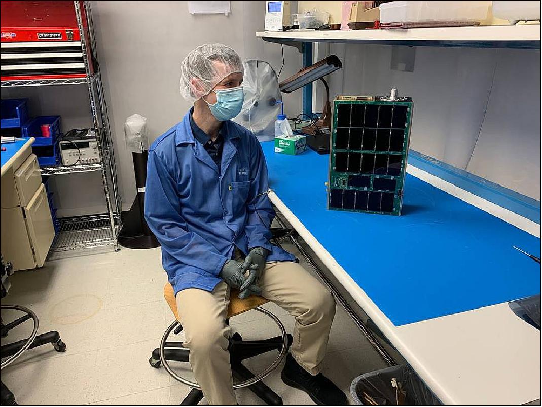
In her first year as a mechanical engineering student at Boston University, Jacqueline Bachrach, a self-described "space kid," enrolled in Walsh's Introduction to Rocketry course. Soon after, she joined his lab and has since taken on an important role in the CuPID mission.
"I've learned a lot of important skills, which I may eventually apply to other missions," said Bachrach, now a junior. "Everyone on the project has so much knowledge that they're willing to share. It's been an incredibly valuable experience, especially for an undergrad."

Scientific Objectives
As the flowing solar wind passes through the Earth's bow shock and into the magnetosheath its magnetic field lines are draped along the Earth's magnetopause. These magnetic field lines of solar wind origin can reconnect with those of the Earth's magnetosphere and change topology. This process of magnetic reconnection is the dominant process of transferring energy into the Earth's magnetosphere. Despite its importance in fueling magnetic storms and disturbances, the macroscale properties of reconnection are not well understood (Ref. 2).
The science objectives of CuPID are to determine the cross- or macroscale spatial and temporal properties of magnetic reconnection. In particular, CuPID will provide the observations necessary to answer the following science questions: (1) Under what conditions is magnetopause reconnection spatially continuous versus discontinuous? (2) under what conditions is magnetopause reconnection temporally steady versus bursty?
Spatial Continuity
The spatial extent over which reconnection occurs along the dayside magnetopause controls the amount of magnetic flux being opened, and subsequently, how much energy is being deposited into the magnetosphere (Fear et al., 2017; Lockwood et al., 1995; Newell & Sibeck, 1993). Understanding the spatial extent of a reconnection separator is important not only as a property of reconnection but also as a mechanism to control the development of geomagnetic storms.
Reconnection lines, also referred to as magnetic separators, may have large or small spatial extents along the dayside magnetopause. Observationally, nearly simultaneous measurements of reconnection by widely separated spacecraft provide evidence for an extended process spanning more than 10 RE along the boundary (Dunlop et al., 2011; Phan et al., 2000). Observations of an extended dayside aurora have also been presented as evidence for an extended reconnection process (Fuselier et al.,2002). Global magnetohydrodynamic (MHD) simulations also provide evidence for a stable and single extended reconnection line for various solar wind conditions (Laitinen et al.,2007). Some models present reconnection to be moving along the boundary as a function of time, however they still find the process to be continuous along the dayside boundary (Glocer et al., 2016; Komar et al., 2013).
By contrast, magnetopause reconnection may occur discontinuously along one or more shorter reconnection lines. Spatial breaks in the aurora have been presented as evidence for gaps between reconnection regions at the magnetopause (Sandholt & Farrugia, 2003). Some transient events in the auroral ionosphere exhibit relatively small east/west extents (Marchaudon et al., 2004; Milan et al., 2016; Oksavik et al., 2004, 2005) which are interpreted as short reconnecting lines (a few RE or smaller). Multi-spacecraft (Walsh et al., 2017; Zou et al., 2020) as well as conjugate measurements at the magnetopause and in the ionosphere also present evidence for spatially localized magnetic reconnection (Zou et al., 2019). Spatially localized and discontinuous regions of reconnection have also been produced in global MHD (Sun et al., 2019) or MHD-PIC models (Chen et al.,2020).

Temporal Variability
The time-dependent nature of reconnection at the Earth's magnetopause also remains unclear. One proposed model is that constant inflow from the magnetosheath drives constant reconnection at the Earth's magnetopause. In support of this idea, in-situ spacecraft measurements (Gosling et al., 1982; Phan et al., 2004; Sonnerup et al., 1981), as well as auroral imaging (Frey et al., 2003), show evidence for continuous reconnection, sometimes lasting for hours.
Alternatively, magnetopause reconnection has been proposed to be bursty or pulsed. A pulsed reconnection model is often invoked to explain the quasi-periodic nature of flux transfer events (Scholer, 1988). Ground-based measurements also provide evidence for bursts of reconnection. Auroral and radar measurements often exhibit transient and spatially localized flow channels and auroral forms. These events are typically interpreted as the ground signatures of bursty reconnection turning on and off at the magnetopause and releasing bundles of magnetic flux that convect tailward (McWilliams et al., 2004; Milan et al., 2000; Nishimura et al., 2014; Walsh et al., 2014).
Projection of Magnetopause Reconnection in the Cusps
Magnetic field lines threading the magnetospheric cusps diverge at high altitudes and spread across the magnetopause boundary. This magnetic connection allows information from along the magnetopause to be transferred to a confined space in the magnetospheric cusps. When magnetic reconnection occurs at one or more places along the dayside magnetopause, charged particles from the magnetosheath flow along the newly opened magnetic field lines into the cusps. For reconnection occurring equator-ward of the cusps, the newly opened magnetic field lines also convect poleward due to the solar wind flow and the magnetic curvature force. A result of these dynamics is a time-of-flight ion dispersion in the cusps, where higher energy particles (and higher densities) are observed near the equator-ward edge of the cusp while lower energy (and lower densities) are observed at higher latitudes (Escoubet et al., 2008; Escoubet et al., 1992; Lockwood & Smith, 1989; Reiff et al., 1977). A diagram of this process is shown in Figure 4.
The shape and properties of these ion dispersions provide information on the properties of magnetopause reconnection. A single steady ion dispersion in the cusp may be evidence for a single steady reconnecting separator at the dayside magnetopause. Multiple ion dispersions observed within a single spacecraft pass through the cusp have been provided as evidence for pulsed magnetopause reconnection (Lockwood, 1995; Lockwood & Smith, 1992; Trattner et al., 2008). Multiple overlapping dispersions have also been presented as evidence for multiple discontinuous reconnection sites along the magnetopause (Newell & Meng, 1991; Trattner et al., 1999) or a cusp in motion (Escoubet et al., 2013).
Figure 5 presents two examples of ion dispersions illustrating features described above. The measurements are from ESA's four-spacecraft Cluster mission and the hot ion analyzer (Reme et al., 1997). In both cusp encounters, Cluster 3 passes through the cusp at a radial distance of 5.9 RE traveling from low to high latitude. The left side of Figure 5 presents a single ion dispersion. At the low latitude edge higher energy particles are observed while the energy decreases with increasing latitude, following the time-of-flight filtering effect. A similar signature is seen in the ion density (bottom panel of Figure 5) where the density peaks and then decays with latitude

In contrast, the right side of Figure 5 presents a cusp crossing where Cluster 3 observes multiple ion dispersions in the cusp. Here the density shows a more complicated structure with multiple peaks corresponding to different ion injections and different modes of magnetopause reconnection. Temporally, multiple ion dispersions occur over the roughly 5 min cusp transit of the spacecraft. As the plasma entering the cusp comes from the magnetosheath and carries high charge-state ions (Walsh, Niehof, et al., 2016), the density structures will generate soft X-rays through charge exchange which will be imaged by CuPID.
Although ion dispersions have been observed by many spacecraft and sounding rocket experiments, there remains a spatial-temporal ambiguity due to the point-nature of the spacecraft measurements. CuPID will image ion dispersion in the cusp from low Earth orbit to differentiate between spatial and temporal models. With the ability to produce images, CuPID seeks to identify under what conditions reconnection is spatially extended versus continuous and under what conditions it is bursty versus temporally stable.
Spacecraft (Mission)
The CuPID 6U CubeSat is designed to study soft X-rays from space. These X-rays will not penetrate the Earth's atmosphere, so an observer must make measurements from space, and CuPID will fly in a low altitude (550 km) polar orbit. The spacecraft will carry the first ever wide field-of-view soft X-ray imager into orbit to make measurements of the Earth's space environment in soft X-rays.
Structure: The spacecraft packs a modular set of avionics as well as soft X-ray telescope and radiation sensor into a small 10 cm x 20 cm x 30 cm box. The self-sustained mission will provide the first regular images of the Earth's magnetic field and space environment in soft X-rays. The 6U CubeSat is roughly 10 x 20 x 30 cm in volume. As an open path must exist for the photons passing through the X-ray telescope, a large space within the spacecraft remains open (right side of Figure 6). The X-ray telescope takes up approximately half of the chassis volume, while the avionics and dosimeter are fit in the other half. To utilize the full available space, the instruments were both built into the chassis structure. Rather than a stand-alone instrument that is mounted inside of the spacecraft chassis, both instruments rely on the chassis for structure and collimation of the fields of view. For the soft X-ray telescope this includes a sunshade, optical element, as well as light baffles. For the dosimeter, the FOV is collimated by the apertures in the chassis.
To reduce unwanted light from entering the telescope from openings outside the aperture, joints between parts on the chassis are fabricated with a three-bounce light-tight requirement. A three-bounce light-tight vent is placed on the telescope to allow venting after launch. The vent also serves as a purge valve to allow the chassis to receive a nitrogen purge while not under vacuum to protect the telescope detector.
The majority of the chassis is fabricated from aluminum, while elements exposed to the X-ray telescope are black anodized to reduce reflection of stray light. The spacecraft interfaces with the Planetary Systems Canisterized Deployer through two rails running the length of the spacecraft. These rails are machined from aluminum and hard anodized. The total mass of the spacecraft is 7.5 kg.
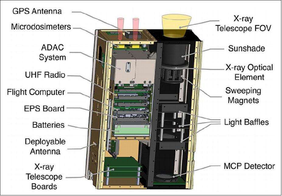
C&DH (Command and Data Handling) system: The C&DH is operated through the Innoflight CFC-300 processor. The spacecraft C&DH communicates with and controls the Ultra-High Frequency (UHF) communications, attitude determination and control subsystem (ADCS), electrical power system (EPS), and NovAtel OEM7 GPS antenna. Both science instruments operate with their own C&DH and pass data to the spacecraft level C&DH. As the spacecraft C&DH receives data, they are manipulated and processed to form a series of onboard data products with varying data-packet size. Data are stored onboard in a 13.4 GB secure digital storage. Each type of data has its own dedicated circular buffer. The dedicated space can store more than 28 days of science and housekeeping data. Time tags are generated from the spacecraft C&DH, and the system clock is regularly updated through the GPS.
The spacecraft C&DH also monitors general spacecraft health with rules configured to enter a safe mode if thresholds are exceeded for elements such as temperature or battery voltage. The system also includes a full reset after a prolonged period without ground contact.
ADCS (Attitude Determination and Control Subsystem): The spacecraft is three-axis stabilized with an Adcole Maryland Aerospace MAI401 ADCS. The system utilizes three orthogonal reaction wheels, magnetorquers, body-mounted coarse sun sensors, a three-axis magnetometer, and star tracker. While observing the cusp, the system has pointing control and knowledge to better than a tenth of a degree. A pointing solution is updated and provided to the system at 10 Hz cadence. The magnetometer is mounted on the opposite side of the spacecraft from the X-ray telescope's optics where permanent sweeping magnets are mounted (position shown in Figure 6).
EPS (Electric Power Subsystem): The system is powered through body-mounted solar panels on two of the spacecraft faces. The panels are fabricated from printed circuit boards with mounted triple junction solar cells. The power subsystem is controlled with an Ibeos (formerly Cubic Aerospace), EPS. The EPS regulates battery charge levels, controls power generation through a peak power tracker on the solar panels, and provides regulated 5 and 12 V DC power outputs to the spacecraft. The battery system incorporates four 3.2 Ah lithium-ion battery cells mounted in a machined FR4 block with aluminum casing with a safety heater. In the 96 min orbit, CuPID's solar panels are illuminated by the sun 65% of the time (34 min eclipse time) to power the spacecraft.
Communication: The spacecraft communicates with the ground through the Astronautical Development, LLC (AstroDev) Lithium 2 half duplex radio operating in the UHF band at 400.5 MHz with AX.25 protocol under a Federal Communications Commission experimental license. On the spacecraft a dipole antenna is held under tension against a 10 x 30 cm face of the spacecraft body during launch and then deployed through a resistor heating a monofilament line to an elastic state which releases the antenna. When stowed, the antenna contacts a conducting post. Once deployed the circuit is broken, providing an electrical signal to confirm deployment.
Launch
CuPID was launched as a secondary (or rideshare) payload on a United Launch Alliance (ULA) Atlas-5 vehicle AV-092) from Vandenberg Space Force Base (SLC3E), California on 27 September 2021 at 18:12 UTC. The primary payload on this mission was Landsat-9 of NASA/USGS. 3)
Orbit of Landsat-9: Sun-synchronous near-circular orbit, altitude = 705 km, inclination = 98.2º, period = 99 minutes, repeat coverage = 16 days. The Landsat-9 satellite will be in coplanar orbit with Landsat-8, 180º apart. This reduces the repeat coverage to 8 days.
Secondary (or rideshare) payloads: Four CubeSats for NASA's 37th Educational Launch of Nanosatellites (ELaNa 37) mission and the Mission Manifest Office at the U.S. Space Force Space Systems Command will begin separating from Centaur at approximately T+plus 2 hours, 14 minutes. The CubeSats are carried on the Evolved Expendable Launch Vehicle Secondary Payload Adapter (ESPA) Flight System, or EFS. It is a ring positioned below the Landsat-9 and above the top of Centaur carrying the four science and national security CubeSats. 4)
ULA's four-meter-diameter metallic payload fairing, built at the company's facility in Harlingen, Tex., protects Landsat-9 and the CubeSats during ascent through Earth's atmosphere. The longest of available Atlas V four-meter fairings will be used, known as the Extra Extended Payload Fairing (XEPF).
• CUTE (Colorado Ultraviolet Transit Experiment), a 6U CubeSat astronomy mission of the University of Colorado at Boulder, Boulder, Colorado.
• CuPID (Cusp Plasma Imaging Detector), a 6U CubeSat space weather science mission of Boston University, Boston Massachusetts.
• CM1 (Cesium Mission 1) of CesiumAstro with two 6U CubeSats (CM1 and CM2), a technology demonstration mission.
Orbit of the secondary payloads: After deployment of Landsat-9, the Centaur stage will reignite its engine two times to maneuver into a different orbit for separation of four small CubeSat rideshare payloads. The CubeSats will be delivered into a near-circular sun-synchronous orbit of 550 km altitude with an inclination of 97.6º.
Sensor Complement (X-ray Imager, Microdosimeter, Magnetometer)
CuPID carries three science instruments, a soft X-ray telescope, microdosimeter suite, and three-axis magnetometer. The instruments provide knowledge of the local energetic particle populations and make images of soft X-rays generated from the magnetosphere. The mechanical structure of each instrument is built into chassis of the spacecraft itself and a summary of the instruments and capabilities are included in Table 1.
Instrument | Parameter | Value |
X-ray Imager | FOV (Field of View) | 4.6º x 4.6º |
Resolution | < 0.22º | |
Grasp (500 eV) | 27.5 cm2 deg2 | |
Energy Range | 0.1–2 keV | |
Microdosimeter A | Electron energy | > 50 keV |
Ion energy | > 1 MeV | |
FOV | 38º | |
Microdosimeter B | Electron energy | > 50 keV |
Ion energy | > 50 keV | |
FOV | 32º | |
Magnetometer | Uncertainty | ±14 nT |
Range | ± 100,000 nT |
X-ray Imager
The first wide FOV X-ray imager flown in space was the STORM (Sheath Transport Observer for the Redistribution of Mass) instrument on the DXL (Diffuse X-ray emission from the Local Galaxy) sounding rocket in 2012 (Collier et al.,2015; Galeazzi et al., 2011; Thomas et al.,2013). A miniaturized version of the STORM telescope was developed and flew on the DXLII sounding rocket in 2015 (Sibeck et al.,2018). The X-ray imager on the CuPID CubeSat Observatory builds on the heritage from these previous flights. CuPID's telescope has a FOV of 4.6° x 4.6° and a focal length of 27.5 cm. This FOV corresponds to 500 eV X-rays and varies slightly with energy due to the energy-dependent range of reflected grazing incidence angles. The position sensing imager will record and telemeter the position and time of each X-ray photon detection. Figure 7 presents images of the telescope as built.

Photons entering the aperture are focused with a single lobster-eye micropore optic (MPO) (Fraser et al., 1992; Kaaret et al., 1992) manufactured by Photonis France SAS. The single 4 x4 cm slumped micropore optic or reflector is composed of an array of 20 x 20 µm square-hole micropores. The surfaces of the pores form reflecting surfaces orthogonal to the surface of the spherical optic, causing X-rays from infinity to focus to an image surface at half the sphere's radius. These pores form an array of channels approximating, in a small area to increase the reflecting surface and thus the effective area of the optic, a Kirkpatrick/Baez system.
Figure 8 presents an image of the bare micropore optical element without a filter. The width of the pore to the length ratio (W/L) used on CuPID is 1/50 . Photons that are reflected off of two orthogonal walls in a pore are fully focused to form the core of the point spread function (PSF) shown in Figure 8c. Photons that are reflected from only one wall form the cross-shaped PSF arms. The full-width-half maximum (FWHM) of the telescope's PSF was characterized with a soft X-ray beam line at 1.49 keV (Al Kα) as less than 0.22°. The instrument's imaging resolution is dominated by the optic performance; thus, the imaging spatial resolution is less than 0.22° or the FWHM of the PSF.

The micropore reflector is an enabling technology for wide FOV imaging as it offers superior FOV per mass ratios than the conventional Wolter I optics traditionally used for astrophysical soft X-ray imaging (Jansen et al., 2001; Trümper, 1982). Previous X-ray missions such as XMM-Newton imaged with a FOV of roughly 0.2° squared, while CuPID has a FOV of 21.2° squared. Although MPOs (Micropore Optics) offer the ability for much larger FOVs, one trade-off is angular resolution. Current Wolter optics have the ability to produce measurements with an angular resolution more than an order of magnitude finer than MPO. As such, the appropriate tool must be chosen for the desired observing target.
A filter composed of a 30.7 nm aluminum and a 217.9 nm polyimide layer is mounted on top of the optical element to suppress unwanted UV and visible light. The filter also blocks incident lower energy particles. The filter mounted on the micropore reflector is shown in Figure 7b. Structurally, the optical element is mounted to a sun-shade (labeled in Figure 7a). Since the telescope is built into the structure of the chassis, the full chassis is fabricated to be three-bounce light-tight to prevent stay photons from entering.
The focal plane consists of a position sensing wedge-and-strip anode board below a chevron configuration MCP (Microchannel Plate) stack. The MCP is coated with KBr for improved soft X-ray sensitivity and has a diameter of 40 mm. Since the MCP can be excited by incident charged particles as well as photons, steps are taken to reduce charged particle contamination. Eight neodymium block magnets with a surface field of 144.6 mT are mounted in an assembly immediately below the micropore reflector (labeled in Figure 6). These serve as sweeping magnets to deflect incident charged particles away from the optical axis and into the telescope walls. The internal baffles then block photons which may be generated from fluorescing when the charged particle strikes the side of the telescope. This technique has been used successfully on a number of previous X-ray missions (Jansen et al., 2001; Burrows et al., 2005). The magnets configuration is designed as a quadrupole which drops off rapidly in strength to minimize the residual field away from the telescope. Further particle suppression comes from the geometry of the optical element and the filter. In lab testing, the CuPID sweeping magnets and filter system have shown to suppress protons less than 10 keV by a factor of 105. Electrons have a smaller gyroradius and thus would be suppressed even more by the sweeping magnets.
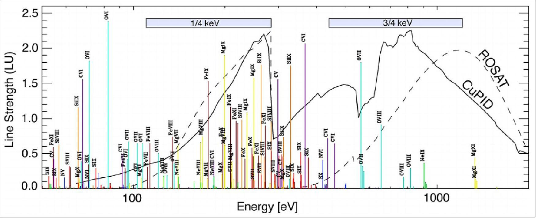
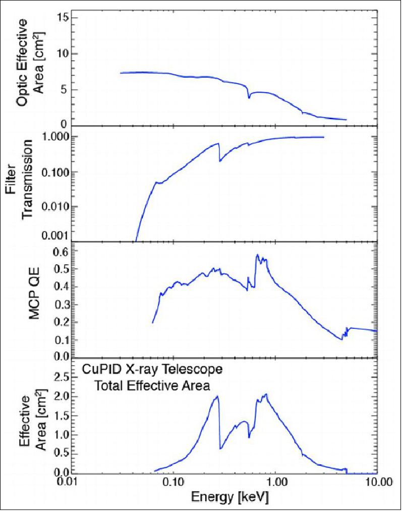
The modeled response of the telescope is shown in Figure 9 and Figure 1. The sensitivity has an energy range similar to that of the 1/4 keV band from the ROSAT spacecraft. This energy band is populated by numerous emission lines from a wide variety solar wind heavy ion species (e.g., Fe(8+ through 11+), Mg(8+ through 10+), O(6+ and 7+), Si(8+ and 9+), C(6+ and 5+)) (Figure 1). Statistical analysis of the cumulative soft X-ray emission from the many lines in the ROSAT 1/4 keV band have shown emission to follow solar wind proton flux well (T. Cravens et al., 2001; Kuntz et al., 2015]. By contrast, solar wind charge-exchange in the higher energy 3/4 keV ROSAT band has been shown to be dominated by prominent high charge state oxygen lines (O7+ and O 8+) (Carter & Sembay, 2008) which do not correlate as well with solar wind flux (Kuntz et al., 2015) due to its strong dependence on the abundance of a single species (Kuntz, 2018).
In orbit the X-ray telescope records time and position information of every photon measured by the MCP. In full position sensing data products, all of these data are telemetered to the ground. This means no time-integration occurs on the spacecraft and a user on the ground can choose over what time periods to integrate. While imaging through the bright cusp, CuPID is anticipated to measure hundreds of counts/s over the FOV.
Microdosimeter
CuPID includes a microdosimeter suite to monitor energetic particle populations and the spacecraft's radiation exposure. The magnetospheric cusps are open magnetic field lines just poleward of closed dayside field lines. Closed magnetic field lines in the outer dayside magnetosphere contain energetic charged particle populations. Although diamagnetic cavities in the exterior cusp may contain energetic particles up to 100's of keV (Fritz et al., 2003; Nykyri et al., 2012; Walsh et al., 2010), open field lines in the low altitude cusp do not adiabatically trap particles and therefore typically do not contain energetic particles populations. The presence or absence of energetic particles can therefore be used to identify magnetic topology and the cusp. Additionally, high energy particles can be a background for an X-ray imager in low Earth orbit (Snowden et al., 1992). The microdosimeter suite will provide a measurement of the intensity of energetic particles and a diagnostic for when X-ray measurements may be contaminated from charged particles. CuPID's suite is custom designed for the mission, using knowledge from other missions with dosimeter-based instruments such as Van Allen Probes (Goldsten et al.,2012; Maure et al., 2013], AeroCube-6 (AC-6) (Blake & O'Brien, 2016), and AeroCube-10 (AC-10) (Turner et al., 2018).
The microdosimeter suite includes two sensors ("A" and "B") designed to measure electrons and ions. The suite is comprised of two identical Teledyne Lo-LET detectors mounted to a printed circuit board, designed and constructed by the Aerospace Corporation. Each detector has a unique foil mounted on the detector mechanical housing between the aperture and silicon detector. The foils screen out lower energy particles and UV light as well as discriminate between charged ions and electrons. Dosimeter A uses an 18 µm thick aluminum foil to block ions below 1 MeV and passes electrons greater than 50 keV. Dosimeter B uses a 0.20 µm nickel foil which passes ions and electrons greater than 50 keV. The microdosimeter and its detectors are shown in Figure 10a. The chassis component and collimating apertures are shown in Figure 10b. The endcap includes other necessary components to the mission such as the GPS antenna and a sun-sensor.
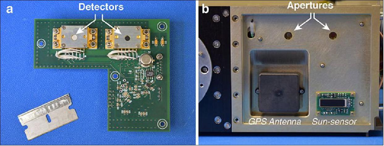
Structurally the dosimeter suite is built into the spacecraft's chassis. The suite is mounted by standoffs to a structural endcap of the spacecraft, co-aligned with the X-ray telescope. The detectors are collimated by machined holes in the spacecraft structural endcap so their FOV are similar to that of the X-ray telescope. Excluding the structural endcap, the instrument weighs just 70 grams.
During normal mission operation CuPID's microdosimeter suite will point toward the zenith, radially out from the Earth. Given the instrument's narrow FOV from a low altitude platform, it will predominantly measure precipitating particles (pitch angle<19° near the cusp and trapping boundary) rather than locally mirroring particles. The instrument FOV was characterized through GEANT4 modeling as well as laboratory experimentation. The instrument was determined to have a maximum FOV of 44° and 42° in dosimeter A and B, respectively. The FWHM of dosimeter A and B is 38° and 32°, respectively. The instrument includes two thermistors mounted on the board and thermal response will be calibrated out during ground processing.
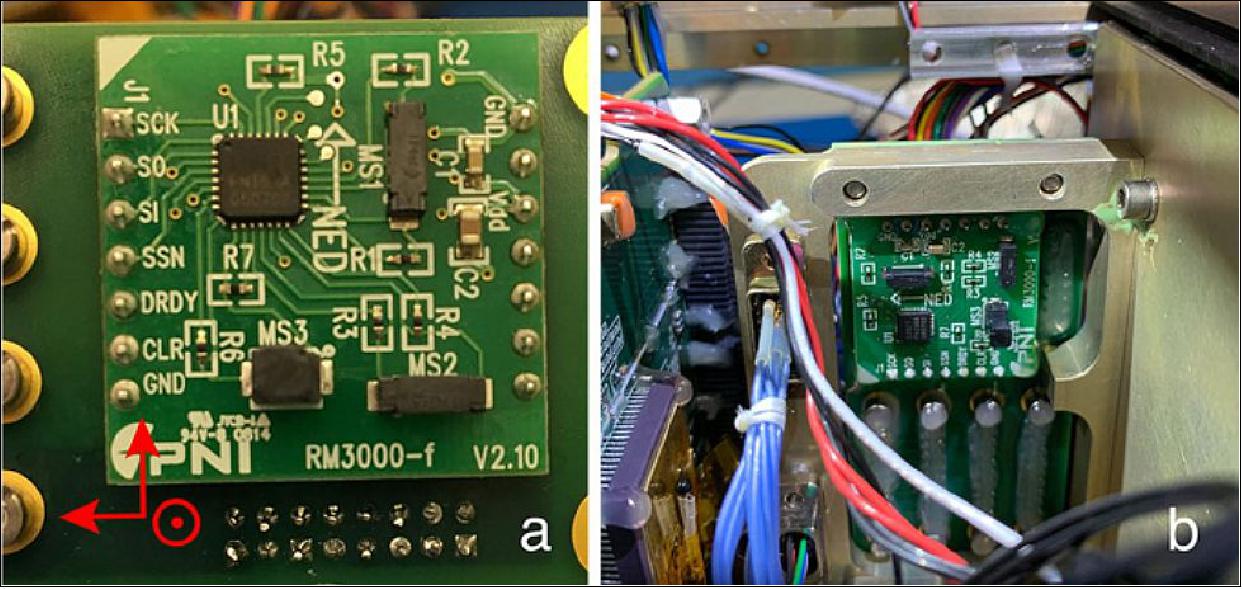
Magnetometer
A magnetometer is carried as part of the ADCS which is calibrated to provide scientifically useful magnetic field measurements. The PNI RM3000 three-axis magnetometer sensor is mounted inside the spacecraft on an interface board shown in Figure 6. A photograph of the mounted magnetometer is shown in Figure 11. The magnetometer is based on the magneto-inductive principle and has been characterized for use as a science instrument for small satellites (Regoli et al., 2018). To minimize background, it is positioned in the spacecraft as far as possible from the permanent sweeping magnets mounted near the telescope aperture. The magnetometer sampling is also coordinated with pulsing by the magnetorquers in the ADAC subsystem. These two elements are phased so sampling of the magnetometer occurs when the magnetorquers are not functioning and vice versa. The integrated CuPID spacecraft was tested in a Helmholtz cage to measure performance with electromagnetic interference from the operating spacecraft. The experiments demonstrated DC measurements with 14 nT uncertainty or 0.05% of the field in CuPID's orbit. Since the sweeping magnets from the soft X-ray telescope are fixed, they have been characterized experimentally and are subtracted off from the DC measurements during this calibration process.
The time cadence of on orbit magnetic field measurement data products is software defined and configurable, but the nominal product telemetered to the ground is 5 s. This time resolution corresponds to 38 km spatial resolution in CuPID's circular orbit, sufficient to resolve a typical auroral current sheet.
Ground Segment
The Mission Operations Center (MOC) and Science Operations Center (SOC) are located at Boston University (BU). The MOC performs planning and scheduling of passes, command generation and uploading, telemetry monitoring, analysis and trending. It sends commands for uploads, requests passes, and receives and processes data. The SOC obtains level-0 (L0) data from the MOC and casts them into L1 and L2 files. L2 files will include calibrated measurements as well as information regarding the galactic soft X-ray background corresponding to the spacecraft pointing. These will be posted publicly and made available to the scientific community (Ref. 2).
Mission Operations
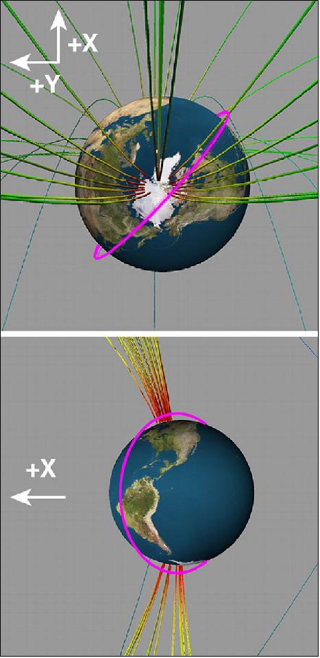
In flight, the spacecraft passes through the cusp footprint in many of its orbits. During nominal operation the spacecraft is aligned so the X-ray telescope and dosimeters are pointing toward the zenith – radially outward from the center of the Earth. An exception to this pointing occurs when the position of the spacecraft would cause the X-ray telescope to point within 35° of the sun. To protect the X-ray telescope from the sun, the spacecraft autonomously rotates to point the largest solar panel at the sun when the spacecraft enters one of these periods and then rotates back after the period has ended. Additional pointing modes to view the cusp from different perspectives may be investigated in an extended mission.
Figure 12 presents projections of the orbit passing through the low altitude magnetospheric cusp. The spacecraft is constructed with a modular avionics system while the science instruments are built into the chassis. Modular exterior panels on the chassis allows for the avionics components to be exposed for manipulation and test without exposing delicate components of the science instruments.
The spacecraft generates significantly more data than can be sent to the ground. To accomplish the science objectives, a number of data products are generated on the spacecraft with different file sizes. With each ground pass, survey data are telemetered to the ground. This survey data set includes basic housekeeping data as well as 10 s averaged dosimeter and X-ray telescope counts with no position sensing information (no imaging). Once interesting time periods are selected, based on the position and pointing of the spacecraft as well as counts from the science instruments in survey files, files with full time resolution and position sensing are brought to the ground with a scientist in the loop. These data allow full X-ray images to be created. The number of counts is low enough that time tag and position sensing information for each X-ray photon are sent to the ground. This format allows images to be made on the ground with a user-defined or variable integration times rather than integrated on the spacecraft. No photon integration is conducted on the spacecraft for the high-resolution data.
Science Operations
Primary science closure comes from coordinated measurements from the soft X-ray telescope and microdosimeters. The SOC has two primary responsibilities, the first is identifying scientifically interesting time periods in which to bring down high-resolution data. The second role is data calibration and formatting for public access. L0 data are transferred to the SOC where it is cast into L1 data and visualized with summary plots. The SOC uses summary plots with spacecraft measurements, pointing, coordinates, and geomagnetic models to determine when CuPID is likely within the cusp and making scientifically useful measurements. These time periods of interest are passed back to the MOC to bring down higher resolution data. Shortly after CuPID's launch, the Magnetospheric Multiscale (MMS) and Time History of Events and Macroscale Interactions during Substorms (THEMIS) missions will regularly pass through the dayside magnetopause, providing conjugate in-situ measurements which map to CuPID's global imaging. Measurements from conjugate missions and ground-based observatories, such as MMS and THEMIS, will also be considered when selecting high-resolution data to telemeter to the ground.
Data products include both survey level X-ray and microdosimeter measurements (10s cadence, no position sensing) as well as high resolution data (full X-ray position sensing). Through X-ray count modeling and radio performance it is predicted that all survey data and roughly 1/3 of X-ray imaging data will be telemetered to the ground. Since the soft X-ray measurements are line-of-sight observations, careful attention needs to be taken when removing background to focus on the near-Earth charge-exchange contribution. This calibration occurs in the generation of L2 data.
In addition to regular science observations, periodic calibration measurements will be made. These come in several forms. First, measurements will be made while pointing the telescope at the dark Earth. As the soft X-ray flux from the non-illuminated night-side of the Earth is negligible, this provides a measurement of background counts (further discussion of background treatment in the following section). Second, the telescope will be pointed at X-ray point sources of known spectrum and intensity; a variety of such sources, both point-like and extended exist in the sky. The exact sources will be chosen after launch based on launch date and position in the sky. Both steps will be repeated periodically throughout the mission to monitor changes in background and sensitivity.
Background Removal
There are three backgrounds which must be characterized and removed in order to isolate the X-ray emission from the Earth's magnetosheath and cusp: the cosmic X-ray background, the near-Earth extreme ultraviolet emission, and the instrument background due to energetic particles striking the detector.
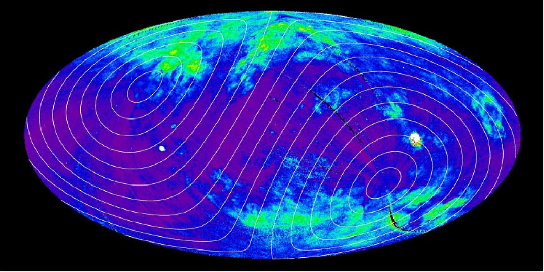
The cosmic X-ray background varies strongly across the sky and has been measured in the 1/4 keV band by the ROSAT All-Sky Survey (RASS, see Figure 13) (Trümper,1982). Although the background is spatially non-uniform, it varies on a range of time-scales all significantly longer than the geocoronal solar wind charge-exchange component and much longer than the CuPID scan time. This means the background remains temporally static and can be removed for the magnetospheric cusp structures that vary on time-scales of minutes. As the ROSAT response is not the same as the CuPID response, the RASS values must be scaled to CuPID using the spectrum of the emission and the CuPID response. Over most of the sky the spectrum is well described by Kuntz and Snowden (2000), but there are large structures, such as the North Polar Spur, the Monogem supernova remnant, the Cygnus superbubble, etc., that must be handled differently. The team applies the techniques of Kuntz and Snowden (2000), with updated spectral models, and a more contemporary understanding of the heliospheric X-ray emission (e.g., Galeazzi et al., 2014) to produce a map of the spectrum of the cosmic X-ray background which can then be converted into a map of the background as seen by CuPID.
The near-Earth extreme ultraviolet emission seen by CuPID results from solar and plasmasphere He+ 30.4 nm (40.8 eV) emission and Lyα emission (121.6 nm, 10.2 eV) scattered into the instrument FOV (Chakrabarti et al.,1982; Rairden et al., 1986; Sandel et al.,2001). Although CuPID has an optical-UV blocking filter, there is some residual emission in these lines. For the CuPID viewing geometry, this emission is uniform across the FOV and varies relatively smoothly in time. The team uses the solar irradiance and the spatial distribution of H and He+ to model this foreground emission following previous work by Snowden and Freyberg (1993).
Finally, the instrument background due to energetic particles striking the detector is expected to be uniform across the detector; the question is the background rate. This may be measured in a number of ways. An absolute rate can be measured by pointing toward the dark Earth. If the particle energy spectrum is relatively stable, the dosimeter measurements can then be used to scale to the correct rate during observations.
Flexible software tools to remove these backgrounds for a variety of missions have been developed by Johns Hopkins University and are employed by the SOC in converted data from L1 to L2.
References
1) Alison Gold, "Small Satellite, Big Questions: CuPID CubeSat Will Get New Perspective on Sun-Earth Boundary," NASA Feature, 10 September 2021, URL: https://www.nasa.gov/feature/goddard/2021/small-satellite-big-questions-cupid-cubesat-will-get-new-perspective-on-sun-earth-boundary
2) B. M. Walsh, M. R. Collier, E. Atz, L. Billingsley, J. M. Broll, H. K. Connor, D. Chornay, T. Cragwell, N. Dobson, S. Eckert D. Einhorn, G. Gallant, K. Jackson, S. Karki, J. Kujawski, K. D. Kuntz, V. Naldoza, R. A. Nutter, J. Moore, C. O'Brien, A. Perez-Rosado, F.S. Porter, D. G. Sibeck, K. Simms, W. Skelton, N. Thomas, D.L. Turner, A. Yousu, A. Weatherwax, A. Zosuls, E. Thomas, "The Cusp Plasma Imaging Detector (CuPID) CubeSat Observatory: Mission Overview," Journal of Geophysical Research Space Physics, Volume126, Issue4, 4 April 2021, e2020JA029015, https://doi.org/10.1029/2020JA029015, URL: https://agupubs.onlinelibrary.wiley.com/doi/epdf/10.1029/2020JA029015
3) "NASA Launches New Mission to Monitor Earth's Landscapes," NASA Press Release 21-126, 27 September 2021, URL: https://www.nasa.gov/press-release/nasa-launches-new-mission-to-monitor-earth-s-landscapes
4) "Landsat 9: Payloads stacked atop Atlas V for launch," ULA, 16 September 2021, URL: https://blog.ulalaunch.com/blog/landsat-9-payloads-stacked-atop-atlas-v-for-launch
The information compiled and edited in this article was provided by Herbert J. Kramer from his documentation of: "Observation of the Earth and Its Environment: Survey of Missions and Sensors" (Springer Verlag) as well as many other sources after the publication of the 4th edition in 2002. - Comments and corrections to this article are always welcome for further updates (eoportal@symbios.space)
Science Objectives Spacecraft Launch Sensor Complement Ground Segment References Back to top