Delfi-C3 (Triple-unit CubeSat Configuration of TU Delft)
Non-EO
Technology and Research
Quick facts
Overview
| Mission type | Non-EO |
| Launch date | 27 Apr 2008 |
Delfi-C3 (Triple-unit CubeSat Configuration of TU Delft)
Overview Spacecraft Launch Mission Status Sensor Complement References
Delfi-C3 is a student-designed nanosatellite mission of the Delft University of Technology, Delft, The Netherlands. The primary mission objectives are the in-orbit tests of the performance of both, a new type of TFSC (Thin Film Solar Cell) technique, and an AWSS (Autonomous Wireless Sun Sensor) and its intrasatellite RF link for data transfer to the OBC (Onboard Computer). Other mission objectives include a flight test of an advanced transceiver and the setup of a distributed ground station network relying on the resources of radio amateurs worldwide. 1) 2) 3) 4)
Delfi-C3 will be the first Dutch university satellite to be flown. The main payloads for the mission are provided/sponsored by the industry; with Dutch Space providing the Thin Film Solar Cells experiment and "TNO Science and Industry" providing the Autonomous Wireless Sun Sensor. TNO Science and Industry is one of several institutes of TNO (Netherlands Organization for Applied Scientific Research), involved in the field of optical instrumentation.
The Delfi-C3 mission, initiated in November 2004, is an ambitious low-cost, short time-to-delivery mission. Its main educational objective is to provide MSc students as a team the opportunity to gain hands-on interdisciplinary engineering experience with the design and realization of both mission and systems aspects of a satellite by providing a challenging real-world application.
Spacecraft
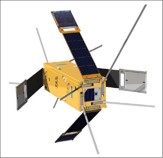
The spacecraft Al structure conforms to the CubeSat "triple cube" standard with a size of 10 cm x 10 cm x 34 cm and a mass of ≤ 3 kg; it also provides the required interfaces for a P-POD (Poly Picosatellite Orbital Deployer) or T-POD launch and deployment procedure. The baseline design for the TCS (Thermal Control Subsystem)) is a passive thermal control system. Delfi-C3 features a passive ADS (Attitude Determination System). A slowly tumbling motion is necessary to allow all four TFSC panels to be exposed to solar radiation. However, a limit is posed on the satellite's rotation rates in order to obtain reliable test results for the TFSC payload. Therefore, rotation rate limiting using magnetic hysteresis materials is applied with PMAS (Passive Magnetic Attitude Control System). PMAS consists of a strong permanent magnet and hysteresis material on one or two other axes to damp the S/C rotation (both high and zero angular velocities are unwanted). Zero angular velocities would not allow proper testing of all payloads distributed over the satellite body. High angular velocities would not allow for enough measurement time per time the payload faces the sun.
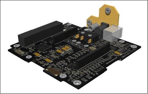
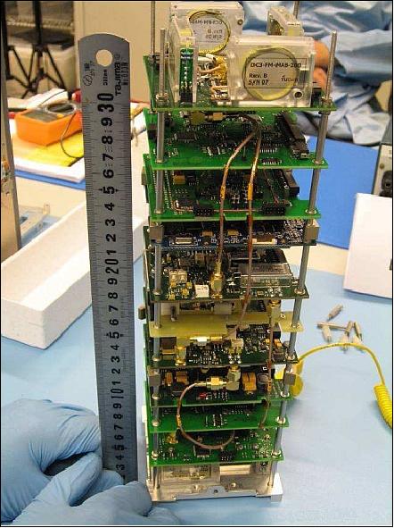
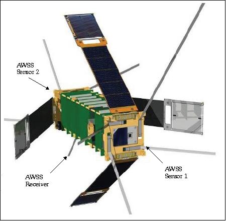
The attitude is being determined by using AWSS. For sun incidence angles beyond the field of view of these sun sensors, an algorithm using solar panel current information is being developed for attitude reconstruction. The distributed CDHS (Command and Data Handling Subsystem) controls the satellite functions and modes and provides commands and data for all relevant onboard subsystems (I2C data bus, use of a star architecture with CDHS as the central hub). The CDHS is designed around an ultra-low power MSP430 microcontroller of Texas Instruments, which is embedded in the flight microcontroller unit board. There is no feature for onboard data storage (this implies that all measured data must be communicated directly). The flightboard is based on the PC-104 standard and is placed in a stack with all other PCB (Printed Circuit Boards). The design of the structure and flightboard force the other PCBs to be of the same size and take stacking connectors into account when laying out their components. 5) 6) 7)
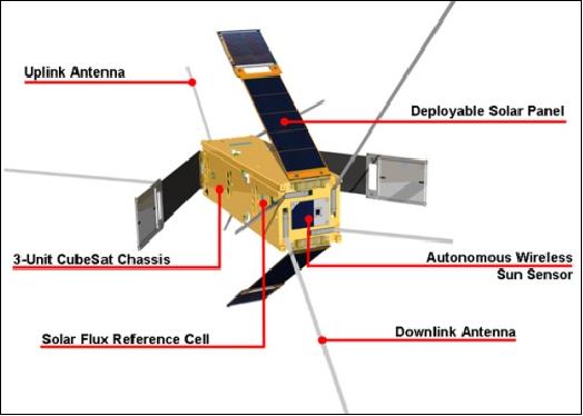
Since the TFSC payload cannot be body-mounted primarily for thermal reasons, it is equipped with four deployable solar panels, each carrying a TFSC payload and triple-junction solar cells (InGaP/GaAs/Ge) for power generation. The four solar panels are being deployed to an angle of 35º. Power of about 3 W (min) is being generated under worst lighting conditions. No batteries have been foreseen for Delfi-C3; this implies that the spacecraft will be powerless during eclipse periods of its orbit. The absence of a battery has 3 reasons:
- The first is that all the experiments only produce useful data when the satellite is in sunlight, this all but eliminates the need for the satellite to function in eclipse
- Secondly, including a battery and control circuitry would have a large impact on the already very limited available mass (up to 3 kg)
- Finally, the required range of operational temperatures for a battery is smaller than what the thermal control subsystem of Delfi-C3 can provide or is required by other components. Since the thermal control subsystem of Delfi-C3 is entirely passive, enhancing it with active components to accommodate a battery would even further increase the complexity accompanying a battery.
The spacecraft is designed for a lifetime of 1 year - with the first 3 months fully operational. During the following 9 months, operations is planned to be handled on a request basis.
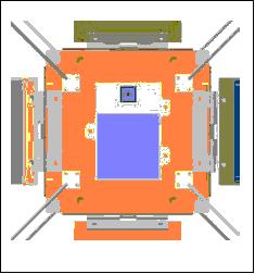
Some Notes on the Delfi-C3 Architecture
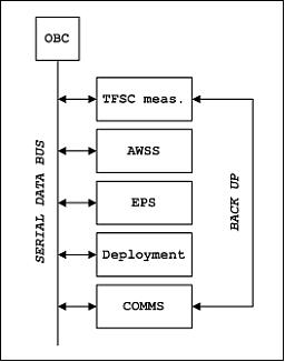
Originally, the Delfi-C3 nanosatellite had been designed using a star architecture with one, single central computer. However, this led to a system bus of more than 120 wires running from top to bottom through the satellite, consuming 18% of the total mass budget. The transition to a decentralized CDHS, where each print is controlled by a dedicated microcontroller, resulted in a mass saving of 11% (star architecture: 0.530 kg, 18% of total; decentralized architecture: 0.214 kg, 7% of total).
The transmitter uses most of the power (2 out of 3 W available). It then became obvious that conventional over-current protection (OCP) of the individual prints and subsystems would consume too large a part of the remaining power to allow satisfactory satellite operations. The solution was the introduction of a decentralized EPS (Electrical Power Subsystem), where a separate controller is used to protect and switch each print or subsystem. That way a power saving (excluding transmitter power) of 11% was achieved (conventional switch and OCP design: 0.182 Watt, 18% of total; decentralized "switching" microcontrollers: 0.073 W, 7% of total). The resulting architecture using no less than 18 microcontrollers is shown in Figure 6.
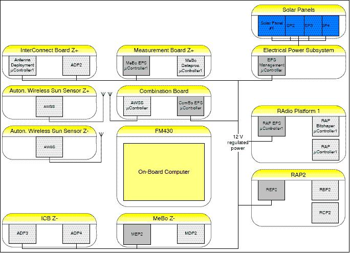
Legend of Figure 6: The light gray boxes represent the decentralized CDHS - while the dark gray boxes represent the decentralized EPS.
Launch
A launch of Delfi-C3 as a secondary payload took place on April 28, 2008 on a PSLV launch vehicle of ISRO from SDSC (Satish Dhawan Space Centre), Sriharikota, India. The primary payload on this multi-satellite flight was CartoSat-2A.
The launch of secondary payloads is being shared by IMS-1 (Indian Microsatellite-1) of ISRO with the following CubeSats or nanosatellites: CanX-2, AAUSat-2 of Aalborg University, Denmark; COMPASS-1 of the University of Applied Science, Aachen, Germany; Delfi-C3 of the Technical University of Delft, The Netherlands; SEEDS-2 of Nihon University, Japan; CUTE-1.7+APD-2 CubeSat of the Tokyo Institute of Technology; NTS (Nanosatellite for Tracking of Ships) of COM DEV / UTIAS/SFL, Toronto, Canada; Rubin-8-AIS an experimental space technology mission of OHB-System, Bremen, Germany.
The Delfi-C3 spacecraft achieved contact on the first orbit with a radio amateur in California. Thereafter, the satellite signal was acquired and decoded at the TU Delft ground station, initial analysis showed the craft to be in excellent condition, all solar panels and antennas were deployed and the internal temperatures and voltages were within the ranges expected.
Orbit: Sun-synchronous circular orbit, altitude = 635 km, inclination = 97.94º, local crossing time on the descending node at 9:30 hours.
RF communications: A dual-redundant communications subsystem is implemented with an AMSAT platform (AX.25 protocol) as backup option to the ATRX (Advanced Transceiver) payload. The AMSAT platform is built using standard commercial-off-the-shelf (COTS) components, providing the same telemetry, telecommand and linear transponder functionality as the ATRX.
The communication antennas are being deployed after orbit injection. There are 8 antennas in total with 4 located on the topside and 4 on the bottomside of the satellite. They consist of 50 cm and 18 cm quarter-wavelength whips that are being phased to provide circular polarization to counteract atmospheric effects on the radio signals. The amateur radio frequency bands in VHF and UHF are being used for communications - to enable radio amateurs worldwide to receive satellite data using a modest equipment setup. One of the two transceivers RAP (Radio Amateur Platform), doubles as the transponder for radio amateurs.
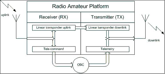
In addition, an ATRX payload is being developed at TU Delft, combining miniaturization with a high DC to RF efficiency and the capability to adapt to different channel conditions. Data will be collected and relayed to a central ground station in Delft by radio amateurs worldwide forming a globally distributed ground station network. The TU Delft ground station will be the only station used for telecommanding. The telemetry downlink employs (VHF, 145.8-146 MHz) a data rate of 1200 bit/s with BPSK modulation, using the amateur standard AX.25 protocol. The uplink is in UHF in the frequency band of 435-438 MHz.
The linear transponder will relay a 40 kHz wide passband from the UHF band to the VHF band. This provides a very flexible system, which can be used by amateurs using a wide variety of modulation schemes. Furthermore, the linear transponder can be used for Doppler tracking to accurately determine the satellite's orbital parameters. Last but not least, a linear transponder can easily be combined with a telemetry downlink. The eight antennas of the antenna subsystem will be phased to provide circular polarization to counteract Faraday rotation in the Earth's atmosphere.
Mission Status
• The Delfi-C3 nanosatellite is operating nominally in February 2016 in its 8th year on orbit (Ref. 12).
• The Delfi-C3 nanosatellite is operating nominally in early 2014 in its 6th year on orbit (Ref. 12).
• The Delfi-C3 nanosatellite is operational in 2013. The mission is considered a full success beyond all expectations. 8)
• In January 2012, the nanosatellite is still operational in its 4th year on orbit (Ref. 11).
• The Delfi-C3 mission is equipped with two AWSS (Autonomous Wirless Sun Sensors). Unfortunately only one is operational. In 2011, the project used the WSRT (Westerbork Synthesis Radio Telescope, trying to detect the 915 MHz signal from the sun sensor to the internal receiver. Before the measurements could be done, the effects of the shielding of the spacecraft case were measured using a spare spacecraft. The final obtained link budget showed a 10 dB SNR when using a 25 meter single dish telescope. Measurements were performed at the WSRT by using multiple radio telescopes placed in the orbit direction. The downlink signal of Delfi-C3 was detected, but the 915 MHz signal was not as it should be. Hence, the project concludes that one sun sensor is malfunctioning. 9)
- Although built with commercial EEE (Electrical, Electronic and Electromechanical) components, the AWSS functions already for more than three years in a low Earth sun synchronous orbit, without showing noticeable degradation in performance. 10)
• The Delfi-C3 mission is operating nominally in 2011 (Ref. 12). 11)
• The Delfi-C3 mission is operating nominally in 2010. 12)
Overall performance of the Delfi-C3 is satisfactory and sufficient data from the two payloads have been and are still being collected. However, the CDHS design has an inherent flaw that quite often prevents data transmission on the bus, leading to either insertion of zero's in the telemetry data, arbitrary switch off of subsystems, a reset of the computer or even a fall back to a very limited back-up mode. If the transmitter is the subsystem that is switched-off, no data at all are transmitted. The driver for the CDHS design has been to limit power consumption as much as possible at the expense of increased risk of bus malfunctioning. As a consequence Delfi-C3 mostly downlinks only valid data during a rather limited period after eclipse or after a pass over the Delft Ground Station, where the transmitter can be switched on again. Also, the accuracy of the on-board measurement system causes data taken at low intensity to be too unreliable to be included in the final data set. 13)
• A worldwide distributed network of amateur radio operators has so far gathered over 90 MByte of payload data. - However, in January 2009, the linear amateur radio transponder failed. A redundant transponder could have prevented the loss of this service to the radio amateurs. TU Delft planned to fly a redundant transponder, but this last function was scrapped prior to launch on the PCB due to an unrecoverable PCB design error. The transponder failure has been pinpointed to the receiver frontend, indicating an open circuit somewhere in the chain from the uplink antennas to the first down conversion stage.
• After the completion of the three-month Science Mode operations (fall of 2008) the satellite has been switched, as planned, to Transponder Mode, serving the radio amateur community as communication satellite DO-64, the first CubeSat to do so (Ref. 13).
In late Sept. 2008, there were the first signs of transponder degradation. On October 14th Delfi-C3 has been switched back to Basic Mode, a simple, housekeeping-only mode, to investigate the problem. In January 2009 it was concluded that the transponder function had failed and on January 29th the satellite has been switched to Science Mode, resuming the collection of data on the two remaining payloads (Ref. 13).
• After six weeks in orbit, the Delfi-C3 mission was already considered a full success. 14)
• TFSC payload results: Initial flight data show nominal IV curve data, with all current, voltage and temperature values within the expected ranges. Since the payload provider, Dutch Space, is mostly interested in degradation of these cells over time, actual degradation data is expected to be available after 2 months into the mission.
• AWSS payload results: First data shows valid data from the AWSS payload, and shows that the wireless link is operational. Further analysis is required in order to reconstruct the actual spacecraft attitude.
• In general, the satellite bus performs nominally. All housekeeping values are within their expected ranges. From the polarity changes of the downlink signal the operations team could deduce an initial rotation rate of Delfi-C3 of 10º/s. This has been confirmed by observing the period of photodiode outputs on the solar panel. After one month of operations this rate dropped to 6º/s. Both values are considerably above the rotation rates expected, and the decay of the rotation is much slower than theoretically predicted.
• The first telemetry showed nominal behavior of all satellite subsystems and all four solar panels and eight antennas were deployed. The onboard software autonomously switched from a 5-minute idle mode to the deployment mode and finally into the science mode. No telecommands where required for Delfi-C3 to become fully operational.
• The first signals after deployment of Delfi-C3 were picked up by a radio amateur operator in California. Shortly thereafter, the Delfi-C3 telemetry data were also received by the TU Delft ground station.
Sensor Complement
TFSC (Thin Film Solar Cell)
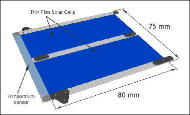
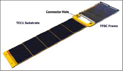
TFSC is of Dutch Space, Leiden, The Netherlands. The objective of the TFSC test is to demonstrate a light-mass and low-cost product for future space applications. These solar cells represent the latest development in the area of photovoltaic cells, consisting of a Copper Indium Gallium diSelenide (CIGS) photovoltaic layer, which is deposited by evaporation on a titanium base layer of 25 µm. The cells are being integrated tile-wise, ensuring a minimal loss of active cell area. The interconnects are covered by the next cell, with an overlap of 5 mm at the longest side. The mechanical interconnection has a low resistance (~1 milli-ohm = 1 mΩ) and is placed between the gilded contact pads under low compressive pressure. The cell efficiency is expected to be > 12% with an emissivity coefficient of > 0.80.
As the temperature of the thin foil cannot be measured directly, it will be measured by determining the electrical resistance of a dummy titanium cell mounted close to the actual TFSCs. The TFSCs cannot be body mounted because of their fragility, but also because of the high cell temperatures that would result from such a configuration. For this reason the four pairs of TFSCs are mounted at the tip of each deployable solar panel.
The performance of the TFSC payload is tested by determining their characteristic IV-curves and cell temperature per TFSC panel, which consists of two cells. The IV-curves are measured by means of a programmable current sink; the temperatures are be measured by determining the electrical resistance of a dummy titanium cell mounted close to the actual TFSCs.
AWSS (Autonomous Wireless Sun Sensor)
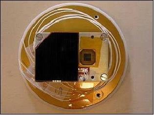
AWSS is of TNO, Delft. The new device incorporates tests of several new technologies. Firstly, the AWSS is autonomous and independent of the rest of the satellite. It is capable of generating its own power using a small solar cell mounted on the sensor. Secondly, the sensor demonstrates a wireless data link to the CDHS (a COTS transceiver is used for the wireless radio frequency link, the UHF/VHF transponder, which doubles as a transceiver in science mode, is of conventional design. It is however, for the first time that such a transponder, allowing five simultaneous users, will fly on a CubeSat). These two technologies will make future satellite design more flexible, as these types of sun sensors can be placed without the need for physical power or data interfaces. The AWSS will also be an order of magnitude smaller than conventional sun sensors; actually it is about the same size as the connector for a conventional sun sensor. 15) 16) 17)
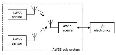
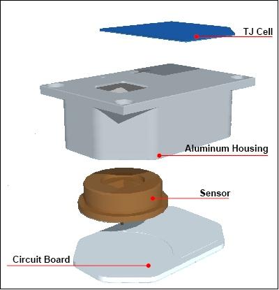
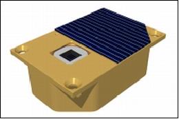
The baseline concept for the AWSS is as follows: the Cubesat houses two analog sun sensors (located at opposite sides of the satellite) that will be fully autonomous and wireless. A flight-proven analog sun sensor is packed in an aluminum housing of size 60 mm x 40 mm x 20 mm. The sensor is attached to advanced readout electronics. The data coming from these readout electronics are transferred to an on-chip RF transmitter emitting the data to the satellite's interior. Power for both readout electronics and RF transmitter is provided by a separate solar cell mounted on top of the device's aluminum housing. This principle makes the sensor autonomous and wireless and thus completely independent of the satellite it is flown on.
The wireless link has been made using an adapted commercial off-the-shelf transceiver. Although wireless data communication on board such small satellites might seem a bit superfluous in itself, implementing this technology adds to modularity and results in a flexible "plug and play" system.
AWSS components:
• Analog Quadrant Sun Sensor (QSS)
• Wireless RF-interface
- UHF FSK link (915 MHz) using a standard Nordic Chipset
- Patch antenna on sensor
- 1 RF-receiver connected to OBC
• Integrated GaAs solar cell (Triple Junction)
• Sensor envelope ~ 60 mm x 40.5 mm x 17.8 mm
• 2 Sensor units, mass ~ 75 g each
• Predecessor to MDSS (Micro Digital Sun Sensor)
Regarding AWSS, the following technologies will be demonstrated:
• Mounting and interconnection of the solar cell
• Application of a micro-sheet (thin layer of rad-hard glass) on top of the solar cell
• Behavior of the sensor during eclipse transfers, regarding the issue of unambiguous detection of sun presence in a difficult power condition
• Robustness of the RF link
• Interconnection technologies.
References
1) R. J . Hamann, C. J. M. Verhoeven, A. A. Vaartjes, A. R. Bonnema, "Nanosatellites for Micro-Technology Pre-Qualification: The Delphi Program at Delft University of Technology," Proceedings of the 6th IAA Symposium on Small Satellites for Earth Observation, Berlin, Germany, April 23 - 26, 2007
2) F. M. Poppenk, R. Amini, "Delfi-C3 Control System Development and Verification," Proceedings of the 57th IAC/IAF/IAA (International Astronautical Congress), Valencia, Spain, Oct. 2-6, 2006, IAC-06-C1.2.02
3) A. Bonnema, W. J. Ubbels, J. Rotteveel, E. van der Linden, E. van Breukelen, "Delfi-C3: Technology demonstrator mission at Delft University of Technology," STEC (Space Technology Education Conference) 2005, April 6-8, 2005, Aalborg University, Aalborg, Denmark
4) W. J. Ubbels, A. R. Bonnema, E. D. van Breukelen, J. H. Doorn, R. van den Eikhoff, E. Van der Linden, G. T. Aalbers, J. Rotteveel, R. J. Hamann, C. J. M. Verhoeven, "Delfi-C3: a Student Nanosatellite as a Test-bed for Thin Film Solar Cells and Wireless Onboard Communication," Second International Conference on Recent Advances in Space Technologies (RAST), Istanbul, Turkey, June 9-11, 2005
5) G. Aalbers, G. N. Gaydadijev, R. Amini, "CDHS design for a University Nanosatellite," Proceedings of the 57th IAC/IAF/IAA (International Astronautical Congress), Valencia, Spain, Oct. 2-6, 2006, IAC-06-B5.7.05
6) B. Vaartjes, R. Hamann, R. Amini, "Integration and Verification of a Command and Data Handling Subsystem for Nanosatellite Projects with Critical Time Constraints: Delfi-C3," 58th IAC (International Astronautical Congress), International Space Expo, Hyderabad, India, Sept. 24-28, 2007, IAC-07-D1.5.03
7) G. F. Brouwer, W. J. Ubbels, A. A. Vaartjes, F. te Hennepe, "Assembly, Integration, and Testing of the Delfi-C3 Nanosatellite," Proceedings of the 59th IAC (International Astronautical Congress), Glasgow, Scotland, UK, Sept. 29 to Oct. 3, 2008, IAC-08-D1.5.6
8) Jian Guo, Jasper Bouwmeester, Eberhard K. A. Gill, "From Delfi-n3Xt to the DelFFi Formation Flying Mission: The Next Step of the Delfi Program," 5th European CubeSat Symposium, Royal Military Academy, VKI (Von Karman Institute), Brussels, Belgium, June 3-5, 2013
9) Mark J. Bentum, Johan Leijtens, Chris Verhoeven, Hans van der Marel, "Measurements on an Autonomous Wireless Payload at 635 km Distance using a Sensitive Radio Telescope," Proceedings of the 33rd ESA Antenna Workshop on Challenges for Space Antenna Systems, ESA/ESTEC, Noordwijk, The Netherlands, Oct. 18-21, 2011
10) C. W. de Boom, N. van der Heiden, J. Sandhu, H. C. Hakkesteegt, J. L. Leijtens, L. Nicollet, J. Bouwmeester, G. van Craen, S. Santandrea, F. Hannoteau, "In-Orbit Experience of TNO Sun Sensors," Proceedings of the GNC 2011, 8th International ESA Conference on Guidance, Navigation & Control Systems, Carlsbad (Karlovy Vary), Czech Republic, June 5-10, 2011
12) Information provided by Jasper Bouwmeester of TU Delf, Delft, The Netherlands
13) Robbert J. Hamann, Jasper Bouwmeester, Geert F. Brouwer, "Delfi‐C3 Preliminary Mission Results," Proceedings of the 23nd Annual AIAA/USU Conference on Small Satellites, Logan, UT, USA, Aug. 10-13, 2009, SSC09-IV-7
14) W. J. Ubbels, C. J. M. Verhoeven, R. J. Hamann, E. Gill, J. Bouwmeester, "First Flight Results of the Delfi-C3 Satellite Mission," Proceedings of the 22nd Annual AIAA/USU Conference on Small Satellites, Logan, UT, USA, Aug. 11-14, 2008, SSC08-X-7
15) W. J. Ubbels, A. R. Bonnema, R. J. Hamann, R. A. Amini, C. J. M. Verhoeven, J. A. P. Leijtens, "The Delfi-C3 Student Nanosatellite, an Educational Testbed for Wireless Technology in Space," Wireless for Space Applications Workshop, July 10-13, 2006, ESA/ESTEC, Noordwijk, The Netherlands
16) Johan Leijtens, Kees de Boom, "TNO and the `Kees' of the incredible shrinking sun sensor," Proceedings of the 4S Symposium: `Small Satellite Systems and Services,' Chia Laguna Sardinia, Italy, Sept. 25-29, 2006, ESA SP-618
17) R. Amini, E. Gill, G. Gaydadjiev, "The Challenges of Intra-Spacecraft Wireless Data Interfacing," 58th IAC (International Astronautical Congress), International Space Expo, Hyderabad, India, Sept. 24-28, 2007, IAC-07-B4.7.08
The information compiled and edited in this article was provided by Herbert J. Kramer from his documentation of: "Observation of the Earth and Its Environment: Survey of Missions and Sensors" (Springer Verlag) as well as many other sources after the publication of the 4th edition in 2002. Comments and corrections to this article are always welcome for further updates (eoportal@symbios.space).
Overview Spacecraft Launch Mission Status Sensor Complement References Back to top