DeMi (Deformable Mirror Demonstration Mission)
Non-EO
MIT
Technology and Research
Quick facts
Overview
| Mission type | Non-EO |
| Agency | MIT |
| Launch date | 15 Feb 2020 |
| End of life date | 08 Mar 2022 |
DeMi (Deformable Mirror Demonstration Mission)
Spacecraft Launch Mission Status Payload Overview Laboratory validation References
Background: 1) DMs (Deformable Mirrors) with actuator counts as high as 128 across the pupil are an essential technology for high-contrast imaging using future large space observatories. 2) MEMS (Micro-Electromechanical Systems) DMs are particularly well suited to the task because of their high actuator density. Their lower size, weight, and power (SWAP) when compared to piezo-electric, electrostrictive, or voice coil designs also may allow easier accommodation in spacecraft, and their low actuator mass makes them resilient to launch-induced vibrations. DMs are also useful for other in-space applications, including optical communication and wide-field scanning telescopes as well as deployable, self-assembling, and other types of reconfigurable optical systems.
MEMS optical devices have flown in space previously, including a single micro-mirror on the MEMS MTEL (Telescope for Extreme Lightning), and a microshutter array. A high-actuator count MEMS DM has been operated briefly during a suborbital sounding rocket flight, but additional validation is needed to show that MEMS DMs are suitable for long-term in-space use on an operational telescope. The devices will need to withstand radiation effects, spacecraft charging, long-term temperature cycling, and extended operation in vacuum. Long-term environmental effects are difficult to replicate in a lab environment, so an actual LEO (Low Earth Orbit) mission is needed to validate the technology. The preparation for this mission will also provide risk reduction for the challenging development of flight software, electronics hardware, and mechanical packaging necessary to operate a DM in space.
The DeMi mission is a 6U CubeSat which will raise the TRL (Technology Readiness Level) of MEMS deformable mirror hardware from 6 to at least 7, demonstrating its operation in the LEO space environment. DeMi will also demonstrate closed-loop wavefront control in space, correcting slowly-varying, high-order aberrations as well as quickly-varying tip-tilt errors. Closed-loop, in-space wavefront control with a MEMS DM is currently at a TRL of 5, and DeMi will also raise this to 7. The performance requirement for the DeMi payload is to measure the surface of the DM to an accuracy of 5 nm, requiring wavefront sensing accuracy of 10 nm.
To complete the primary objective of demonstrating deformable mirror operation in space, the DM actuators must be commanded and their positions measured accurately. The DeMi payload includes a custom DM driver and a Shack-Hartmann Wavefront Sensor (SHWFS) to measure the optical surface through wavefront reconstruction. There are two options for DM illumination, an external aperture viewing a star, or an internal laser diode.
Adaptive optics (AO) have been commonly used on ground based telescopes, such as the Keck I and II telescopes, to correct for the negative impacts that atmospheric turbulence has on astronomical imaging. While AO is commonly known to have uses on ground based telescopes, it also has applications on space telescopes. AO can be a critical difference in reaching the necessary contrast, of 10-10, to image Earth-like exoplanets. It allows for corrections of wavefront error caused by optical imperfections and thermal distortions. These correction capabilities allow launches of cheaper optics, improve imaging resolution, and have applications for optical amplification in intersatellite communication and various military projects.
Spacecraft
DeMi is a 6U CubeSat mission of MIT (Massachusetts Institute of Technology) with the objective to demonstrate the use of adaptive optics, specifically a MEMS-deformable mirror, in space. Not only will the DeMi mission characterize the deformable mirror on-orbit, the mission will also demonstrate deformable mirror control using closed-loop image plane sensing and wavefront sensing on internal and external light sources. DeMi uses COTS components like Thorlabs mirrors, Pixelink complementary metal-oxide-semiconductor cameras, and a Boston Micromachines Corporation “multi” deformable mirror. 3)
In August 2017, BCT (Blue Canyon Technologies Inc.) was awarded a contract by Aurora Flight Sciences, a subsidiary of Boeing, to build and test a new 6U-class CubeSat bus for the DeMi (Deformable Mirror) demonstration mission led by the MIT/STAR ( Space Telecommunications, Astronomy and Radiation) Laboratory and funded by DARPA. MIT is providing the micro-electromechanical system (MEMS) deformable mirror (DM) instrument for the mission. Aurora Flight Sciences is managing the project and systems integration. 4)
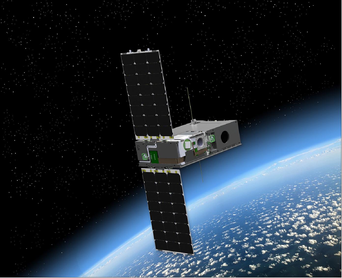
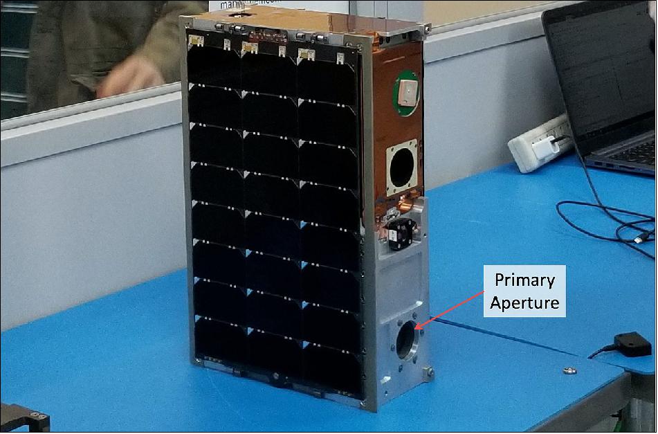
The DeMi CubeSat is based on the Blue Canyon Technologies XB6 platform, a 6U (30 cm x 20 cm x 10 cm) spacecraft bus comprising solar panels, batteries, command and data handling electronics, communication systems, and ADCS (Attitude Determination and Control System). The 6U spacecraft is being developed at BCT’s Spacecraft Manufacturing Center located in Boulder, CO. For DeMi, the bus contains a Cadet U UHF radio capable of receiving commands from the ground and downlinking data to a 18 m dish at NASA Wallops Flight Facility at a rate of 1 Mbit/s. It will also have an Astrodev Lithium 2 UHF radio for backup communications at up to 9.6 kbit/s. The backup UHF ground station is located on the MIT campus in Cambridge, MA. The XB6 bus includes the XACT ADCS, which is made up of a star tracker, an inertial measurement unit, magnetic torque rods, and reaction wheels. The system is capable of accurately pointing the bus with stability better than 10 arcseconds (1σ) in all axes. 5) 6) 7)
Launch
The DeMi CubeSat was launched on 15 February 2020 (20:21 GMT) on the Cygnus NG-13 flight of Northrop Grumman with a Antares 230+ rocket from Virginia Space’s MARS (Mid-Atlantic Regional Spaceport) at NASA’s Wallops Flight Facility. 8)
The flight results from this mission will provide useful data for future space telescopes that plan to use MEMS deformable mirror technology.
Orbit: Near circular orbit, altitude of ~400 km, inclination = 51.6º.
Small satellites hitching ride to space on Cygnus 9)
Three small satellites are hitching a ride to the International Space Station aboard the Cygnus supply ship. Two of the spacecraft are sponsored by DARPA (Defense Advanced Research Projects Agency). Another was developed at NASA’s Ames Research Center in California.
• The Red-Eye 2 microsatellite is the second in a series of Red-Eye satellites developed by DARPA. The Red-Eye satellites aim “to develop and demonstrate technologies that increase the utility of low-cost microsatellites,” according to NASA.
- The first Red-Eye satellite launched to the station aboard a SpaceX Dragon cargo ship last year, then was released from the NanoRacks Kaber deployer in June 2019.
- “Red-Eye will demonstrate lightweight, low-power, gimballed inter-satellite communications links appropriate for the class of satellites approximately 100 kg in size,” NASA wrote in a summary of the experiment. “Red-Eye will also demonstrate new attitude control components, onboard processors, and software-defined radios.”
Two CubeSat-class satellites are also aboard the Cygnus supply ship for release from the space station’s smaller satellite deployer.
• The DeMi (Deformable Mirror Demonstration Mission), a 6U CubeSat (the payload is ~4.5U in volume and 2.5 kg in mass), was developed at MIT (Massachusetts Institute of Technology). The deformable mirror instrument will demonstrate technologies that could be used on future space telescopes making high-contrast observations of exoplanets around bright stars. Such precision observations, which will use coronagraphs to blot out the light of the star, require the use of deformable mirrors inside the telescope that can be adjusted using internal actuators, according to MIT. DARPA is funding the DeMi experiment, and Aurora Flight Sciences is managing the mission.
- The deformable mirrors “can correct image plane aberrations and speckles caused by imperfections, thermal distortions, and diffraction in the telescope and optics that would otherwise corrupt the wavefront and allow leaking starlight to contaminate coronagraphic images,” MIT scientists wrote in a summary of the demonstration.
• NASA’s TechEdSat-10 nanosatellite, a 6U CubeSat, is the next in a line of experimental CubeSats developed at the Ames Research Center in California. According to NASA, the TechEdSat 10 spacecraft will function as a high temperature, accurate deorbit reentry nanosatellite.
Mission Status
• July 28, 2020: A recently deployed DARPA CubeSat seeks to demonstrate technology that could improve imaging of distant objects in space and allow powerful space telescopes to fit into small satellites. DARPA’s Deformable Mirror (DeMi) CubeSat deployed from the International Space Station July 13, beginning the technology demonstration of a miniature space telescope with a small deformable mirror called a microelectromechanical systems (MEMS) mirror. 10)
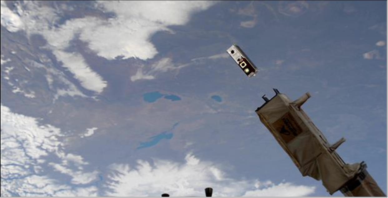
- DeMi made first contact about a week following launch, demonstrating the expected power from its solar arrays, as well as correct spacecraft pointing and stable temperatures. The team will focus on payload checkout over the coming days.
- Deformable mirrors can adjust the shape of their reflective surfaces to correct for the effects of temperature and mechanical changes on a space telescope, improving image quality. The experiment will measure how well a MEMS deformable mirror performs in space, from the rocket launch through its time in orbit experiencing the thermal and radiation environment.
- “Space telescopes currently in orbit are limited in ability to detect and distinguish small, dim objects next to large, bright objects – for example, dim exoplanets next to bright stars. Deformable mirrors have proven successful in ground-based applications, but their performance has not been tested in long duration space operations,” said Stacie Williams, the program manager for DeMi in DARPA’s Tactical Technology Office. “Our goal is to demonstrate the benefits of a MEMS deformable mirror to actively correct the images of distant objects in space.”
- The primary mirror of the DeMi telescope is about an inch wide, and the deformable mirror surface is about the size of a dime. The DeMi payload can observe stars with the telescope and use an internal laser for calibration measurements of the deformable mirror. When the payload observes stars, the deformable mirror will keep the star centered on the imaging camera. The MEMS mirror has 140 actuators, tiny moving surfaces that control the mirror shape. Calibration measurements will track the performance using about 50 actuators over time in the space environment.
- DeMi also aims to demonstrate wavefront correction, where the payload measures the wavefront, or shape of misalignments in the optical system. The deformable mirror corrects these errors by changing shape, acting like the opposite of a distorting funhouse mirror. After making observations, the DeMi spacecraft will downlink images from the wavefront sensors so operators can monitor the deformable mirror behavior from the ground.
- The DARPA DeMi team includes Aurora Flight Sciences; Massachusetts Institute of Technology, which designed and built the optical payload; and Blue Canyon Technologies, which designed and built the spacecraft bus. DeMi arrived to the space station in February aboard a cargo resupply mission, packed into a NanoRacks CubeSat Deployer. The mission is anticipated to last about a year.
Sensor Complement
Optomechanical Design
To characterize the operation of the 140 actuator DM (Deformable Mirror), a stable wavefront is required. To increase redundancy and allow cross-calibration, DeMi employs both image plane and pupil plane (Shack-Hartmann) wavefront sensing. The design of a relatively complex, many-element optical system for a CubeSat poses several challenges: a constrained payload volume (less than 4U of the 6U spacecraft), a potential operating temperature range of -5ºC to 20ºC, and cost constraints. To address these challenges, a design based on COTS (Commercial Off-The-Shelf ) diamond-turned OAP (Off-Axis Parabola) mirrors is used. Off-the-shelf available focal lengths and apertures are chosen to enable rapid lab prototyping. All OAPs are catalog parts from Thorlabs Inc (Newton, New Jersey, USA). For the flight mirror assemblies, non-reflective surfaces are procured un-anodized and will be wrapped in polyimide tape for increased emissivity. Reflective surfaces will be aluminum with a SiO2 protective coating. Early designs employed singlet lenses which induced significant chromatic aberration when observing stellar targets in broadband. Other designs including commercial, multi-element lenses corrected chromatic aberration while providing a large FOV (Field of View), but added significant mass and complexity, as well launch and thermal environment survival risk.
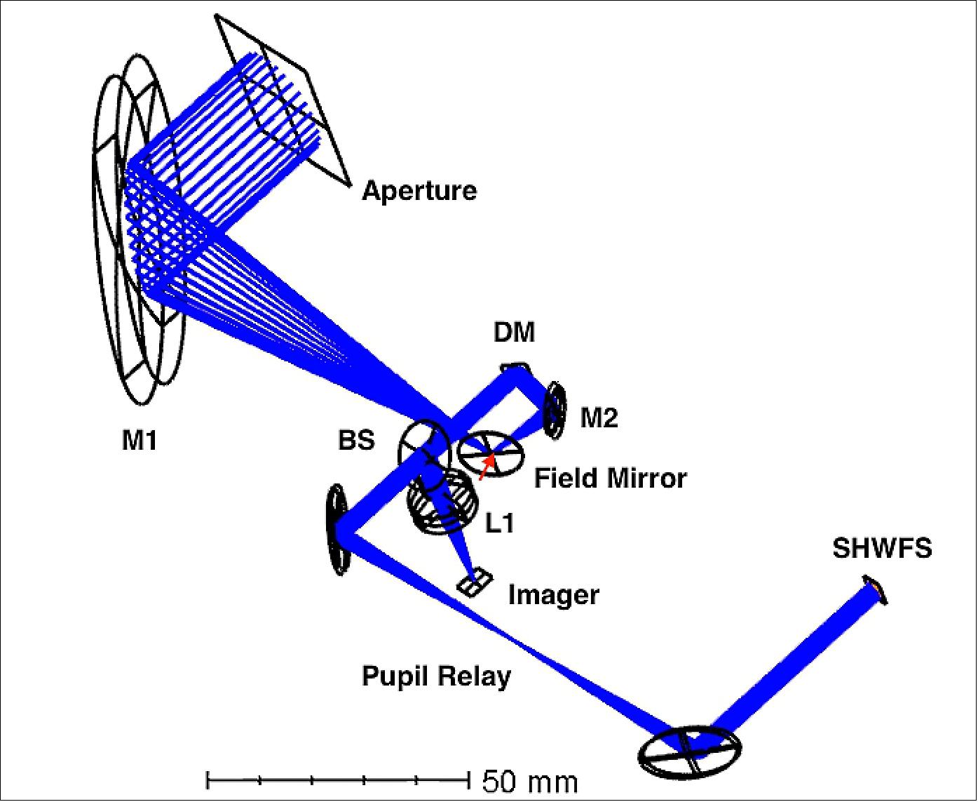
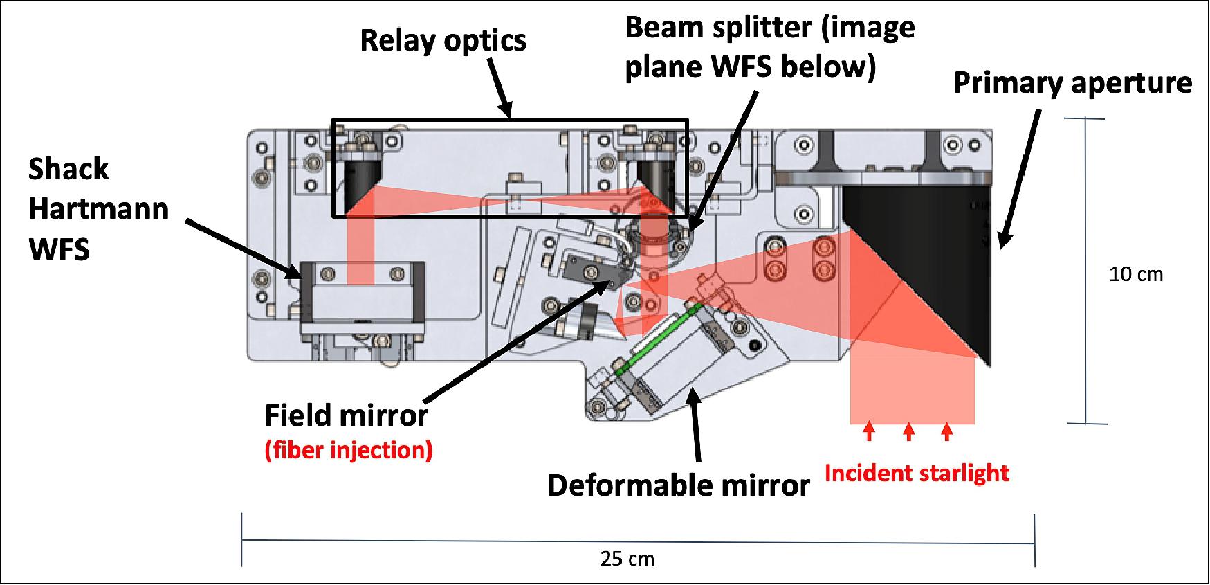
The layout shown in Figure 4 includes a telescope assembly, the deformable mirror, a pupil relay and two imaging cameras. The primary mirror is a 50.8 mm diameter, 100 mm focal length 90 degree OAP, which will be under-illuminated by an input baffle, not shown. A polished aluminum field mirror manufactured in two parts allows injection of monochromatic light into the image plane via single mode fiber. A 12.7 mm diameter, 15 mm focal length OAP collimates the beam and illuminates the approximately 5 mm aperture of the deformable mirror in a pupil plane. A pair of 50 mm focal length, 12.7 mm diameter OAPs relay this plane to the wavefront sensor. The wavefront sensor samples the beam with 150 um lenslets, providing better than Nyquist sampling of the DM actuators. Before the relay, a non-polarizing 50/50 beamsplitter picks off light to the imaging camera, which is fed by a 25 mm focal length achromatic lens. The imaging camera can function as either a passive monitor of wavefront state or an active wavefront sensor controlling the deformable mirror. This optical train provides diffraction limited image performance and provides redundant sensing of the DM surface.
Optomechanical Tolerances: The optical assembly is toleranced in Zemax using Monte Carlo simulations of alignment in each degree of freedom that impacts system wavefront error. This provides the fine adjustment levels required to keep the misalignment contribution to the imaging system wavefront budget below λ/4 to maximize the stroke available for active control.
Mechanical Design: The structural design of DeMi mainly focuses on adjustability of the position of optical elements so that they can be aligned. Repeatability of this alignment is also important, as is robustness of the assembly to mechanical vibration. The structure must have the ability to align the optical elements, to survive a 100 g load in all three axes, and maintain alignment through as much of the expected -5ºC to 20ºC thermal range as possible; all while minimizing manufacturing costs. Built-in adjustment is necessary to aid in alignment during mechanical integration and tolerate variation in manufactured optics. Quick repeatability of alignment after disassembly is also required. The aluminum OAPs greatly simplify optic attachment when compared to glass optics whose coefficient of thermal expansion varies greatly from that of aluminum mounting brackets. Aluminum optical bench and mounting structures are thermally connected to each other and the OAPs with thermally conductive gap filler.
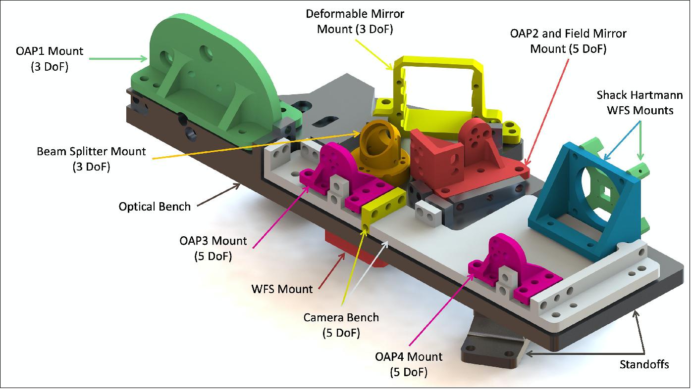
For DeMi, kinematic mounting of optical components is achieved through the use of fine-pitch (Thorlabs M2.5 x 0.20) adjustment screws with ball ends, which are threaded into appropriate fine-pitch bushings. These are paired with socket-head machine screws with Belleville washers to provide retention force. The adjustment screws allow precise translation along their axis and, when combined in groups of 2 or 3, allow precise rotation of a mount or part in all three axes.
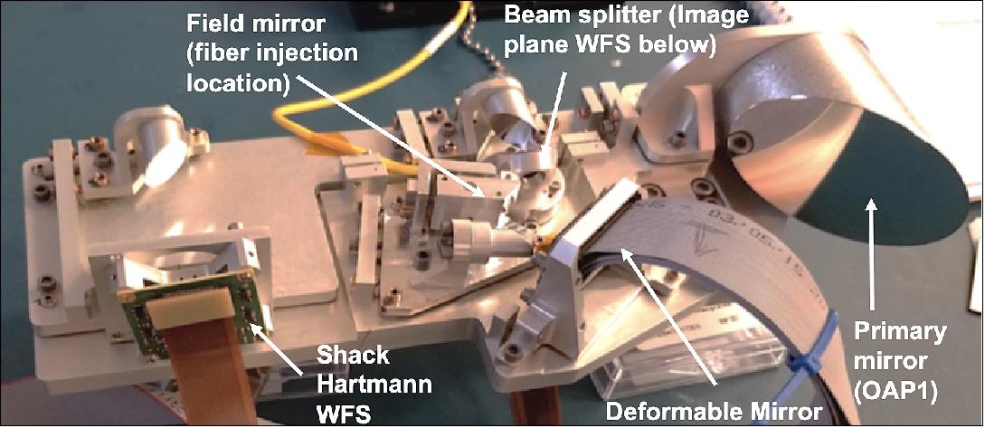
To make the structure more rigid, the underlying optical bench is a monolithic piece. This base is attached to the bus through three 6Al-4V titanium stand-off flexures, which form an exact constraint and allow the payload to survive launch-induced vibrations. Five subassemblies are attached to the optical bench using kinematic mountings. These subassemblies hold in place one field mirror, four off-axis parabolic mirrors, the deformable mirror, one beam splitter, lenses, and cameras, as shown in Figure 5. To make sure the focal lengths and position adjustments do not change with temperature variations, the mirrors and major structural components are all made of the same material, 7075 aluminum. In order to apply consistent torque to the fasteners, the fine-pitch screws are adjusted before the fasteners are torqued.
A finite element analysis was performed in SolidWorks to demonstrate that all interfaces would survive the vibration loads of the launch environment. The RMS vibration amplitudes were applied as a simulated 100 g static load applied along each axis simultaneously. This load was chosen to be more conservative than the requirements of the NASA GEVS (General Environmental Verification Specification), which represents a 3σ case of applied acceleration due to launch-induced vibrations. The resulting reaction forces on each of the fasteners were analyzed for failure modes such as bolt shear and tension failure, bolt head pull-through, and bolts near part edges shearing through the sides of their holes. The preload tension required to to prevent gapping between parts under these loads requires fasteners made of stainless steel with more than 100 ksi (7030 kg/cm2) tensile strength, such as A286. Results of this analysis are shown in Table 1. All failure modes except gapping have margins greater than a factor of 3. As a non-critical failure, a safety factor above 1.8 was deemed to be acceptable for gapping.
Failure mode | Bolt shear | Bolt tension | Grapping | Head pull-through | Plate shear-out | Net tension |
Margin | 5.76 | 3.96 | 1.875 | >10 | 3.24 | >10 |
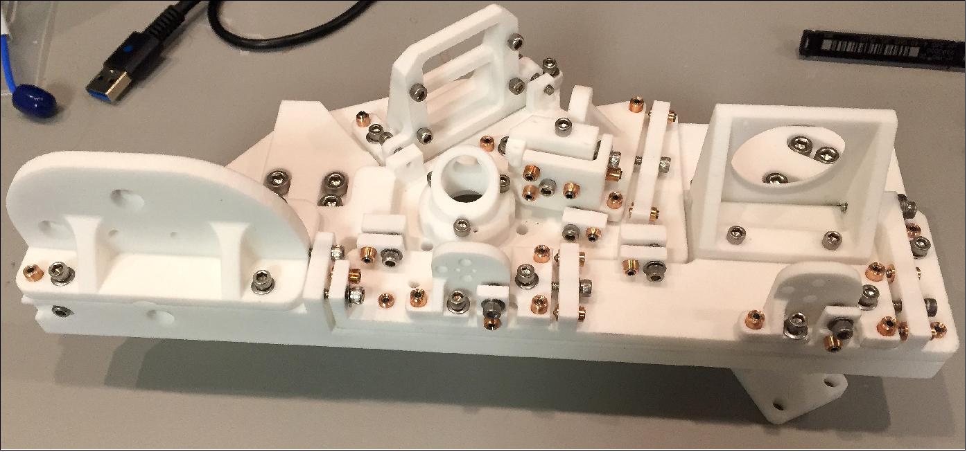
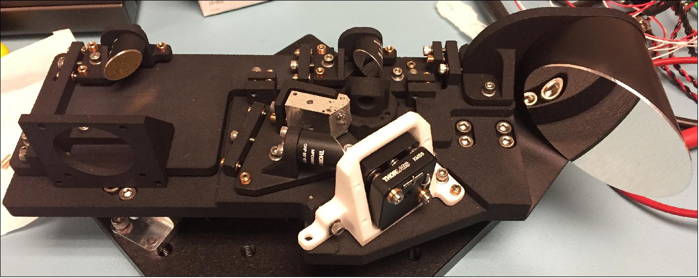
3D Printed Model: A prototype of the DeMi structure was 3D-printed in order to perform fit-checks and test the optical alignment procedure prior to final fabrication. Some adjustments were made after initial fit-checks so a second version was 3D-printed. Optical elements were installed in the 3D-printed model and initial attempts at coarse alignment of the optics were made using a Zygo VeriFire QPZ interferometer. Alignment was not performed to a satisfactory level, as the printed model is not tightly toleranced and the adjustment screws do not fit tightly in all the parts. However, this served as a valuable rehearsal of alignment procedure, and based on these experiences, minor changes to the alignment adjustment mechanisms have been incorporated into a final design. Specifically, steel pins were added to act as contact points for the ball-tipped adjustment screws to prevent deformation of the aluminum surfaces. At this time, the design has been sent to the Boston University Scientific Instrument Facility for fabrication of the flight version in aluminum. Figure 6 shows the first version of the prototype and Figure 7 shows the second prototype with representative COTS OAPs mounted.
Thermal Analysis: Thermal analysis was performed for the DeMi payload to assess the temperature ranges that components will experience during all stages of the mission. In order to maintain negligible (< 10 nm wavefront error) thermoelastically induced misalignments on optical elements, all optical elements and the bench are required to maintain their absolute temperature to 20ºC ± 4ºC during operational periods (up to 1000 seconds) and temperature gradients must be less than 2ºC between optical components. The DeMi payload must maintain temperatures within the survival ranges of all components at all times. Temperature limits for each component are shown in Table 2. The payload uses thermal interface material to create known thermal interfaces between kinematically mounted components, and uses two 2.5 W heaters (located on the underside of the optical bench) to actively maintain component temperature requirements.
Component | Survival Temperature Range (ºC) | Operational Temperature Range (ºC) | ||
Min | Max | Min | Max | |
Deformable Mirror | 0 | 80 | -10 | 30 |
Raspberry Pi CM3s | -25 | 85 | -25 | 85 |
DM Driver Boards | -40 | 50 | -40 | 50 |
Power Supply Board | -55 | 65 | -55 | 85 |
PixeLink Cameras | -45 | 85 | 0 | 50 |
Optics Bench | 5 | 35 | 16 | 24 |
A thermal model was developed by Blue Canyon Technologies to model predicted spacecraft wall temperatures for hot and cold extremes of orbital conditions, as determined by solar beta angle and exact orbital parameters. Using this data, five cases are identified as bounding thermal cases and are modeled in Thermal Desktop: hot operational, hot storage, cold operational, cold storage, and commissioning. In the operational cases the heaters are used if necessary and the payload electronics are active and dissipating heat. In the storage cases the heaters are used if necessary, but the electronics are powered off. The commissioning case captures conditions immediately after spacecraft deployment before heaters or electronics are powered on. These five cases were simulated in Thermal Desktop using the bus wall temperature data as boundary conditions, modeling conduction paths within the payload and to the bus, internal radiation (both payload to host and payload to payload), component power dissipation, and heater control laws.
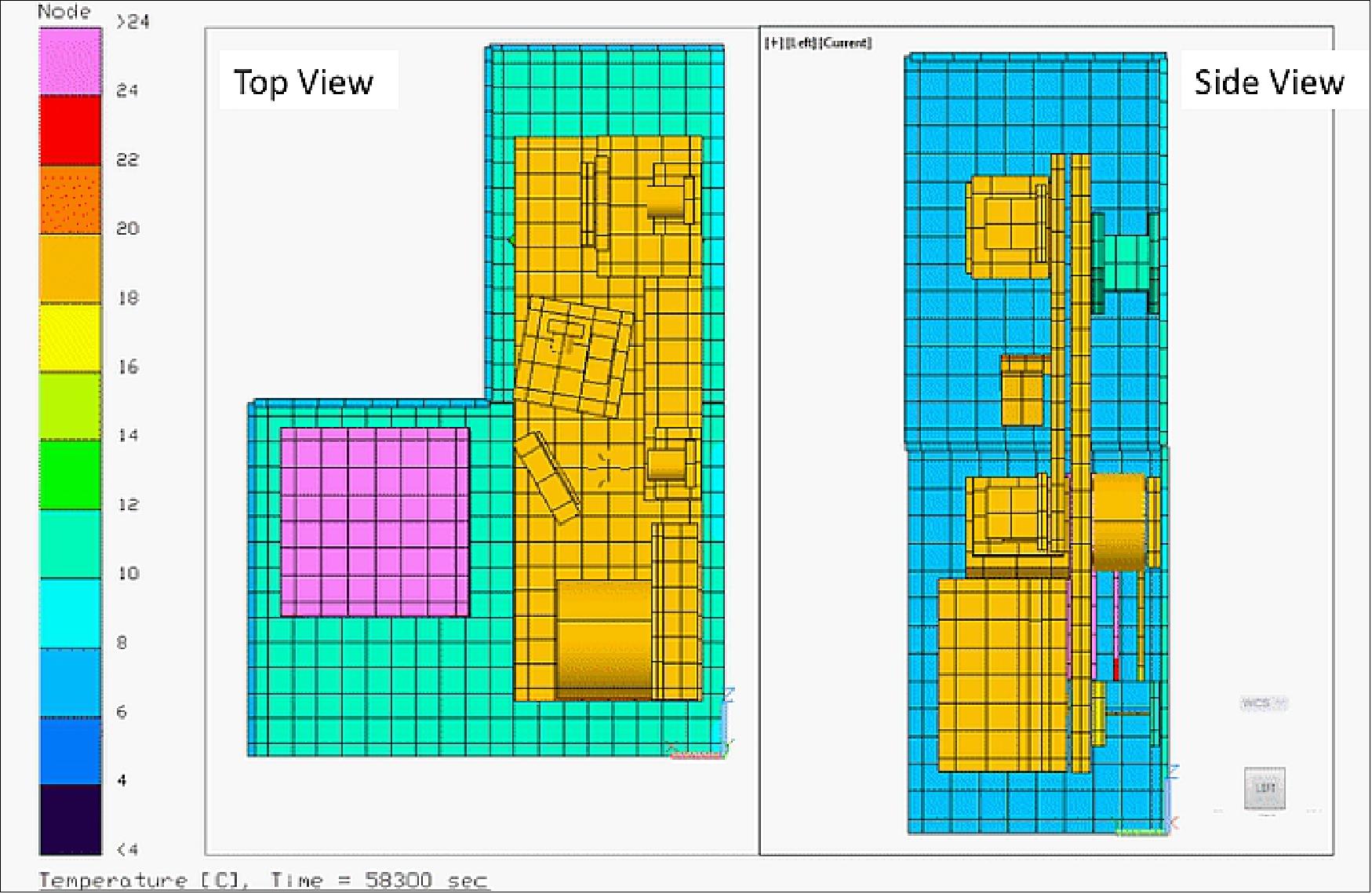
The input wall temperatures and the results of this analysis are shown in Table 3. For all cases examined, the DeMi payload components remained within their required temperature limits. Optomechanical temperature requirements refer to those of the bench and DM, while the electronics requirements refer to the other components in Table 2. In the commissioning case, the optical bench comes within 1ºC of its predicted survival range without permanent misalignment of optical components. More analysis and testing are required to verify the thermal model and the bench's survival temperature. Thermal stability during operational periods was found to be ±1ºC across the optical bench and mounted optical components, and all components remained within their survival temperature range both in storage and commissioning phases of the mission. Figure 8 displays a temperature map of the DeMi payload for a single time step in the hot operational case.
Test case | Conditions (ºC) | Results (ºC) | Limits (ºC) | ||
S/C Wall Temp. | Optomech. Temp. | Electronics Temp. | Optomech. Temp. | Electronics Temp. | |
Hot Storage | 3 - 18 | 10 - 12 | 9 - 13 | 5 - 35 | -25 - 50 |
Hot Operational | 3 - 18 | 18 - 20 | 10 - 48 | 18 - 22 | -25 - 50 |
Cold Storage | -3 - 13 | 10 - 15 | 3 - 9 | 5 - 35 | -25 - 50 |
Cold Operational | -3 - 13 | 18 - 20 | 7 - 45 | 18 - 22 | -25 - 50 |
(Cold) Commissioning | -3 - 13 | 5 - 6 | 7 - 45 | 5 -35 | -25 - 50 |
Environmental Testing: Preliminary thermal cycling tests have been performed on DeMi off-axis parabolic mirrors, which were not rated by the manufacturer for the expected on-orbit temperature range. These Thorlabs aluminum mirrors have a SiO2 optical coating and black anodization on non-optical surfaces. In order to determine if these coatings would remain adhered to the mirrors after thermal cycling, a test unit was repeatedly cycled between room temperature and 60ºC. Adhesive tape was then applied and removed in an attempt to induce the coatings to flake, and both coatings survived this test without damage. However, the outgassing properties of the dyes used in the black anodization are unknown, so the flight parts will be non-anodized but will be wrapped in polyimide tape to maintain thermal emissivity in an acceptable range.
Full functional testing will be performed on the integrated DeMi payload in a vacuum environment over the expected spacecraft wall temperatures of -3ºC to 18ºC to replicate the expected hot and cold cases in Table 3. Vibration tests will also be performed on a vibration table with a fixture to replicate attachment to the spacecraft bus, at low levels of 4 g RMS in order to verify workmanship. Full functional testing will be performed before and after vibration. Once the payload is integrated into the spacecraft, it will be subjected to environmental testing including Thermal Vacuum (TVAC), shock, and vibration in accordance with the NASA GEVS or applicable launch service provider requirements. The spacecraft will be treated as a protoflight article and so will be tested to qualification levels for a reduced duration.
Concept of Operations
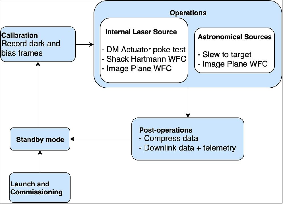
The DeMi payload has two operational modes, one that looks at an internal calibration target laser source, and the other that looks at external astronomical sources, e.g., star targets. To observe external star targets, the spacecraft will slew to point at a star and use the image plane WFS for closed-loop control of the DM to correct tip-tilt errors. The PSFs collected by the image plane WFS will be used to collect photometric measurements of stars with V band magnitudes less than 3. The internal laser calibration source will be used to measure the performance of the DM over time by poking each actuator and measuring the resultant wavefront on the Shack Hartmann WFS. The internal laser calibration source will also be used to demonstrate wavefront control using the Shack Hartmann WFS for closed-loop control of the DM while measuring the PSF on the image plane WFS to monitor the results. The DeMi concept of operations is summarized in Figure 10. 12)
Uplink of spacecraft and payload commands, and downlink of telemetry and science data will be accomplished through the use of two different RF communication links. The primary Telemetry, Tracking, and Control (TT&C) link will use an Astrodev Lithium 2 Radio (Li-2) on the spacecraft, and another Li-2 radio that is integrated into the UHF ground station on the MIT campus in Cambridge, MA. This primary TT&C link will operate at 9.6 kbit/s, with an uplink frequency of 449.75 MHz and downlink at 401.3 MHz. It and will primarily be used for commands and housekeeping telemetry. The high-rate data downlink will use a Cadet-U UHF radio, manufactured by the SDL (Space Dynamics Laboratory), and will use a ground station at the NASA Wallops Flight Facility. This link will operate at 3 Mbit/s, with uplink at 449.75 MHz and a downlink at 468 MHz. The high-rate capability will be used to downlink images and wavefront sensor data from the payload, as well as large blocks of payload and bus telemetry.
Command and control capability is implemented with Blue Canyon Technologies (BCT) extension of the Ball Aerospace COSMOS ground station software, provided with a software bridge to interface with the Li-2 transceiver. Commands implemented in COSMOS include both direct and scheduled actions for each the satellite bus as well as the DeMi payload itself, passed through by the bus. Commands in each segment are implemented as CCSDS telemetry and command packets, with messages sent directly to the payload wrapped in with a secondary header for delivery. Scheduling of observation sessions is done by commanding the bus to point to a target star once the spacecraft and payload are in the external observation configuration. The bus is also commanded to boot and configure the payload for the observation. The payload's subsequent actions are automated; cues from timed commands from the bus to payload indicate coarse pointing error as the bus pointing settles on the target. The payload may issue corrective pointing commands to the bus for fine adjustments of accumulated tip or tilt error observed by the payload.
Operator commands to the bus also include initiating downlink of buffered telemetry and data packets from the payload. Downlink scheduling requests indicate whether the the Cadet radio or the TT&C Li-2 are to be used in advance of the downlink to allow for buffering of data to the correct radio. Ground commands passed directly to the payload will be primarily used for configuration adjustments and requesting specific portions of the payload data for downlink.
The CCSDS File Delivery Protocol (CFDP) is not available on the DeMi bus. File uplink is provided as an extension to the existing command packet. Files such as subprocess executables or configuration file replacements are packetized to no larger than 65535 Byte segments per the Space Packet Protocol. Upon receipt by the payload, the segments are verified against included checksums, saved, and reassembled. File downlinks use fragmentation and reassembly on the ground. Both ground-side fragmentation and reassembly use Python scripts developed outside of COSMOS. COSMOS is used to form headers and record transmission/receipt of packets being via COSMOS. Information about the available data onboard that has not yet been downlinked is provided in a predefined file that is regularly updated. The file informs operators of the range of available data for downlink.
Electronics Design
The DeMi payload electronics stack uses a set of redundant payload computers (PLCs), dual high-voltage driver boards for the DM, and a power distribution board. There are also interfaces for control and feedback from the DM, both payload imaging sensors, and the internal laser control source. Power is sourced from the BCT satellite bus, which also provides data interfaces for each of the PLCs. A high-level diagram summarizing the DeMi electronics system is shown in Figure 11.
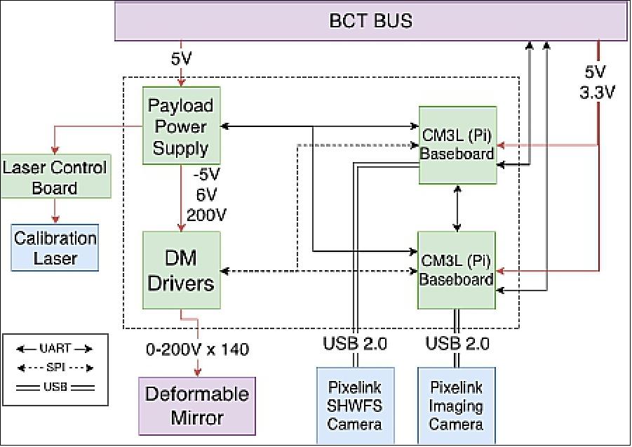
Payload Computer (PLC) Board: The payload computer board has interfaces for the Raspberry Pi Compute Module 3 Lite (CM3L) computing platform. The board provides the following interfaces: independent UART, as well as 3V3 and 5V power interfaces to the satellite bus; USB 2.0 via Samtec T1M-05 to host the Pixelink PL-D775; dual micro-SD card spring-less interfaces; the SODIMM slot to host the CM3L; top and bottom hermaphroditic mezzanine connectors to pass all stack-interfaces to (or receive from) the companion PLC board. The stack-interfaces include multiple SPI interfaces and control lines to the deformable mirror high voltage driver boards, UART interfaces to each the power board MCU as well as the accompanying companion PLC, and internal laser source control. This configuration isolates power and ground, which is provided directly to each PLC from the satellite bus, with a shared reference. To accommodate this, as well as the higher TTL 6 V of the driver boards versus the CM3L's 3V3 maximum, a pair of 6-channel unidirectional isolators limits all incoming signals from other boards, as well as key outgoing signals.
The primary CM3L UART \PL011" is used for the dedicated 115.2 kbaud data interface with the satellite bus, connected by an Omnetics Nano-D very low profile 9 pin connector. The ”mini UART" is reserved as a debugging interface. The two remaining UARTs to the power MCU and the companion PLC are implemented as software UARTs at a lower 9.6 kbaud.
The 3V3 power source from the satellite bus is provided directly to all associated components with the following exceptions. The USB PL-D775 interface is the sole load on the 5V source on each PLC board, enabled by a CM3L-controlled load-switch. The CM3L needs a 1V8 power input as well as the direct 3V3; this is stepped down on the PLC board from the 3V3 rail. Each SD card is operated independently and is enabled by load switches on the 3V3 rail. The ADM6316 watchdog timer (WDT) low-voltage reset is softened by a Schottky diode and capacitor, isolating it from sudden CM3L current draw increases which it is sensitive to.
The PLC implements a reset-and-failover scheme in recognition that each the CM3L and micro-SD cards from which it boots are COTS components with possible failure modes. While an industrial-rated micro-SD card is used, high-current-draw failure modes which may cause permanent flash failure are mitigated via fast-shutdown current-limited load switches. Reset indicators from these load switches are one of two reset conditions observed by this circuit. The other is the GPS PPS provided by the satellite bus data interface. Suppressible by the satellite bus, the PPS serves as a directly controllable reset function via ground commands and reset conditions provided to the satellite bus. In either of these reset conditions, the hardware reset sequence is triggered by the external watchdog timer: the output toggles the CM3L's reset (”run") input directly while simultaneously flipping a JK-flipflop in toggle mode to its opposite value. The opposing outputs of this toggle control each of the micro-SD cards in opposite fashion, and the positive output also controls the 5-channel SD-mux. When the toggle flips during a reset, it causes the next boot to be from the other micro-SD card, safeguarding the system from becoming stuck booting from a potentially corrupted micro-SD card. Resets are accounted for by the payload software and can be triggered internally to reattempt booting from the prior micro-SD when appropriate. Note the WDT's output to the CM3L reset must be made via a noninverting buffer to prevent the internal capacitance of the CM3L ”run" pin from slowing the rise of the line voltage below the minimum slew rate required by the flipflop's input.
High Voltage Driver 32-channel Unit: The original DM driver electronics from BMC were too large to fit on the DeMi mission, so a COTS-based miniaturized DM driver was developed as described in Haughwout 2018. 13) The final design consists of three 80 mm x 80 mm x 10 mm circuit boards and is shown in Figure 12.
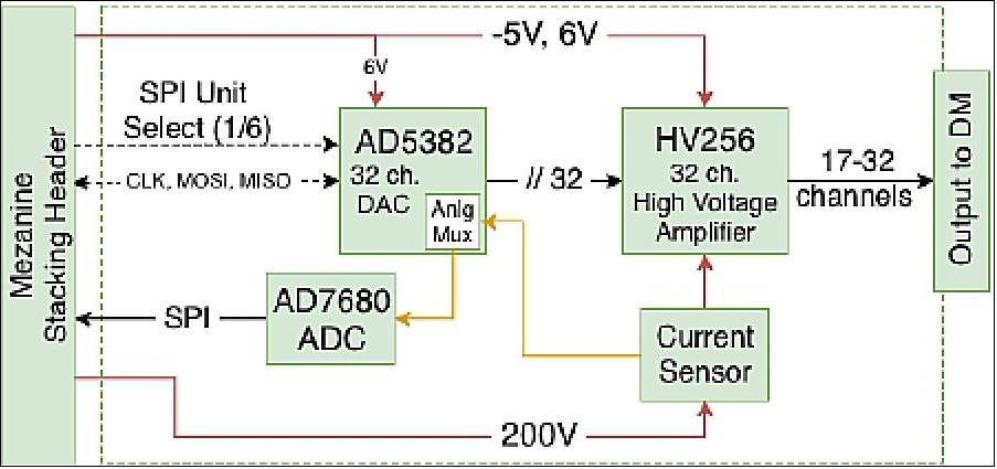
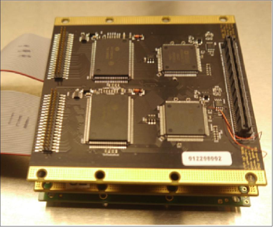
Built around the AD5382 DAC and the HV256 high voltage amplifier (32-channels each), a single DeMi driver ”\unit" provides 32 controllable channels. These channels are aggregated in sets of three per driver board. The channels are controlled by a SPI interface to the DAC. The AD5382 utilizes additional control signals to standard SPI not shown. The SPI clock, data, and additional control lines are shared between all six driver units on both boards, forming a shared bus between the drivers and the PLCs. Excluded from this shared bus is the control-select line (termed ”SYNC" on the AD5382), for which an independent control line is provided to the DAC of each unit. Care must be taken not to exceed fan-out limits of the SPI pins as units are added, but no fan-out buffers were needed for the configuration presented. The shared bus pins can be passed all the way through the stacking mezzanine, but the independent SYNC lines must be deconflicted between boards by staggering the pin connections to allow the control to pass through one board to reach the other, yet present all control lines to the PLCs at once.
An ADC interfaced via SPI is also provided in each unit. While it could have been combined with the DAC SPI, it is separated to isolate risk of conflicts with the DAC which is of foremost importance. The interface for the ADC of each unit is combined with the other units as a bus with offset control lines in the same manner as the prior interface described. The ADC's source input is the single analog output from the AD5382's analog mux, which provides configurable output sourced from any of the DAC's 32 channels, as well as 4 additional mux external inputs. An external input for each unit's AD5382 analog mux is populated by the output of a current sensor configured to monitor a shunt on the high-power input to the HV256. This current sensor allows monitoring of the HV256's consumption, which varies predictably with channel output level. In the case of actuator failure, current consumption can be used to corroborate a diagnosis if the failure is electrical in nature.
Laboratory Validation
DM Driver Test Results: Design validation is performed on a 32-channel DM controller prototype. The testing configuration utilizes an external High Voltage power supply, a Raspberry Pi 3B (Pi) and a 32 actuator bench-top deformable mirror (normally used with the large form factor vendor-provided driver) to validate the functionality and baseline the performance of the new driver. The functionality of the driver and the accompanying sensing devices are confirmed through these tests. The output levels of the driver are directly observed with a Fluke multimeter at a range of values to confirm the expected high voltage values are being delivered (0-250 V). With a calibrating laser aligned at the center of the CMOS sensor, the DM is commanded to induce a linear tip and tilt on the wavefront, and the resulting displacements are observed in the image to be in the expected direction. Each actuator is then individually driven to 50% (with all other actuators relaxed at 0 V such that the inter-actuator effects are minimal) and the resulting distortions are qualitatively observed to confirm functionality of each individual driving line and actuator channel. Following wavefront sensor calibration, additional tests will be performed to quantitatively measure the resulting wavefront motion from the driver's signals and to calibrate the driver accordingly.
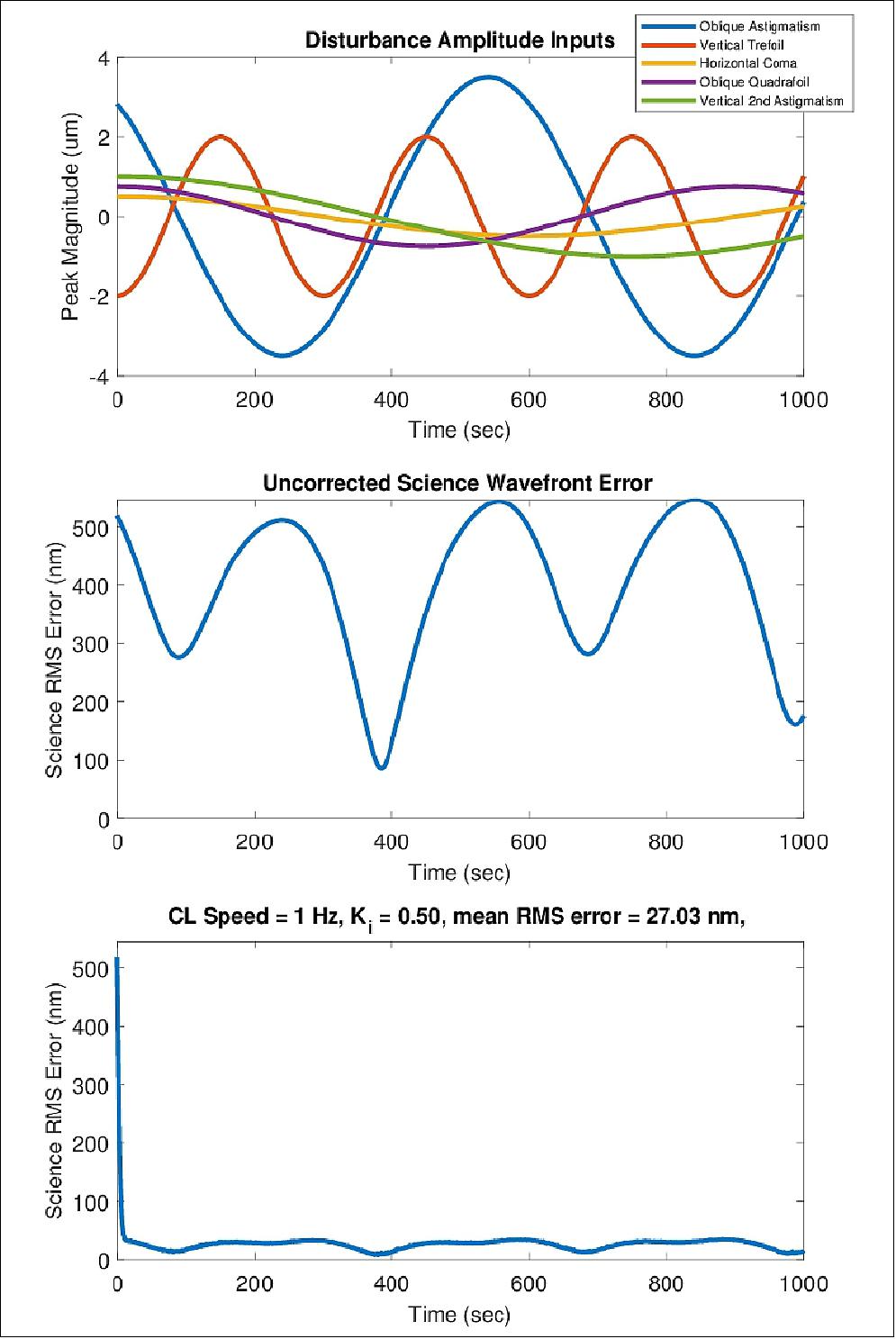
Prior to integrating the prototype driver, a proof of concept closed-loop controller is demonstrated to show the capability of the available benchtop deformable mirror for rejecting oscillation and introduced disturbances. For the purposes of this demonstration, a tip-tilt disturbance on the order of half the experimentally determined throw range of the deformable mirror was introduced at 1 to 4 Hz. The Raspberry Pi 3 is used to compute the x and y centroid of the laser on the CMOS sensor at each frame at a 4 Hz rate. The centroid position is then used as error feedback to a proportional-integral control law in Matlab which interfaced with the vendor's DM driver. This demonstration is promising for the implementation of the same demonstration with the prototype payload computer which we can control at a much faster and more consistent rate than in the demonstration configuration. The initial demonstration is limited to 4 Hz by the speed of the Matlab loop and communication overhead between the Pi and Matlab computer.
Wavefront Sensing Test Results: A representative optical system containing a DM, image-plane sensor, and SHWFS is used to perform validation of wavefront sensing methods. The objective of this test was to verify that a single DM actuator poke could be qualitatively seen in the reconstructed wavefront for each wavefront sensing method. The light source for this test was a single mode fiber laser at the image plane of a Vixen A80Mf refracting telescope used as a collimator and beam expander. The flatness of the resulting wavefront is verified manually with a shear plate. The beam is then reflected by a Boston Micromachines Mini DM before being split and directed to a flight-like image sensor and SHWFS. To provide initial spot centroid positions for the SHWFS, data was initially collected with the DM in a relaxed state. Then an actuator near the center of the DM is chosen and actuated with 75 V, inducing a single poke on the DM surface. Data is collected on both the SHWFS and image plane sensor in this configuration. Next, an additional actuator is poked near the edge of the DM so additional image-plane data could be collected to enable dOTF processing.
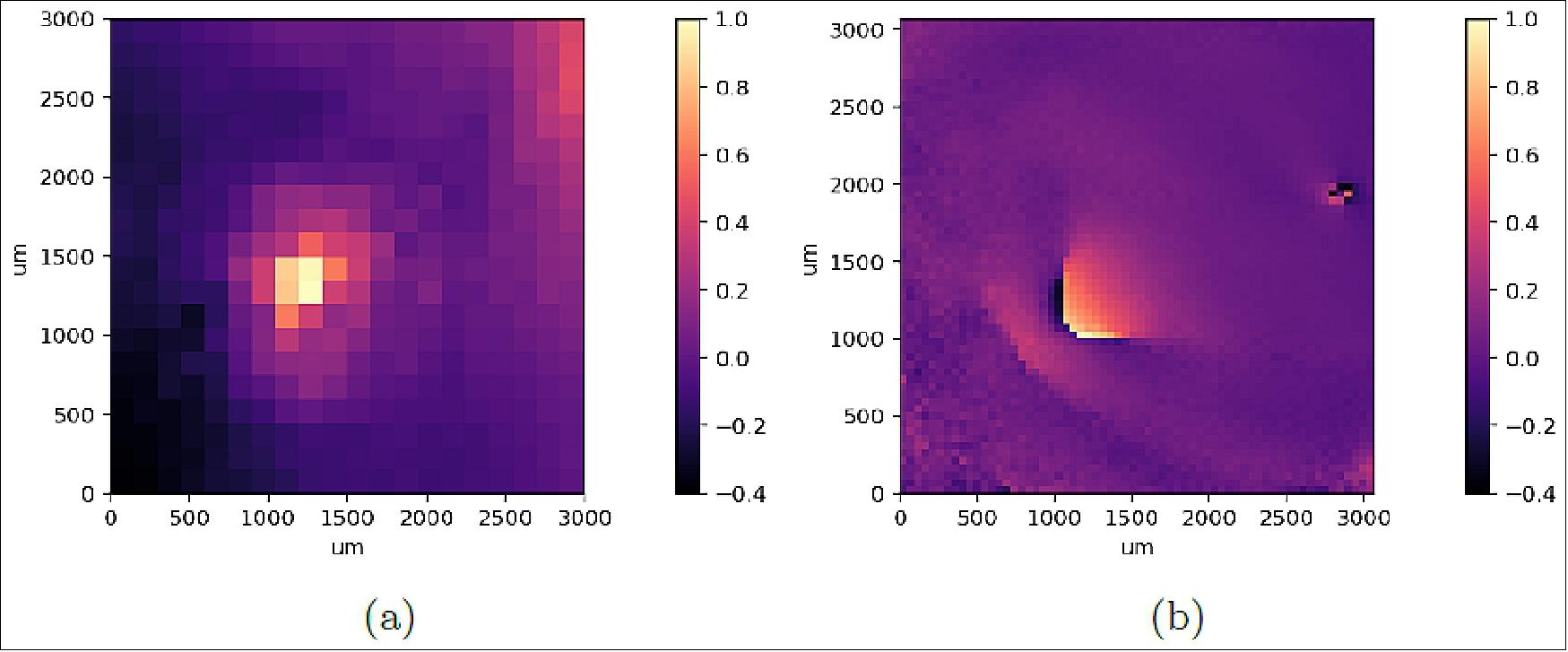
Results are shown in Figure 10. Both methods show a distinct actuator poke in the expected location. Note that the dOTF results are cropped to show a single version of reconstructed wavefront. Color scale is shown on a relative scale; additional work is required to calibrate both methods to the true amplitude of the wavefront.
Integration and Testing
Engineering Model: The DeMi payload is in the integration and testing stage at MIT. The MIT team has assembled and aligned a full flight-like Engineering Model (EM) for end-to-end system testing. Assembling the EM served as a dry-run to test assembly procedures for the flight model. In the process of assembling and aligning the EM minor mechanical modifications were made and implemented for the flight components to improve the flight integration process.
The project aligned the EM payload optics using a Zygo interferometer. The engineering model payload was aligned so that the dominant aberrations as measured at the SHWFS location were -0.492 waves of focus and 0.218 waves of astigmatism. However, after this alignment procedure was completed, the DM was removed in order to place a protective cover on it before placing it back into the payload, and the alignment of the EM has degraded as a result. The screws were torqued to the appropriate values with a torque wrench throughout the alignment process, and after alignment was completed, the screws were staked in place with 3M Gray 2216 epoxy. The full aligned EM optical bench is shown in Figure 16. Alignment of the flight model is underway and should reach a similar level of alignment. We do not plan on removing the DM before staking the payload in its final configuration.
The DeMi team has conducted testing of the miniaturized DM driver electronics with a Zygo interferometer. In this test, the DM was mounted directly in front of the interferometer so the actuator displacements could be measured directly. The testing procedure began with taking a measurement with the DM powered on but unactuated to subtract from each actuated image to reduce noise in image processing. For each actuator, an interferometer measurement was taken with the actuator displacement set to 15% and 30% of the maximum voltage. Displacements higher than this could not be measured consistently by the interferometer. These measurements were analyzed by subtracting the unactuated measurement, cropping the measurement to the area surrounding the displaced actuator, and fitting a Gaussian to the measurement to compute the magnitude and width of the displacement. The mean displacement measured for 30 V actuation is 70 nm with a standard deviation of 15 nm while the mean displacement measured for 60 V actuation is 269 nm with a standard deviation of 18 nm.
A representative sample of the actuators were also measured with the Zygo instrument with the BMC driver for comparision. For 30 V actuation, the mean displacement was 88 nm with a standard deviation of 13 nm and for 60 V actuation, the mean displacement was 244 nm with a standard deviation of 9 nm. The variation in these values is likely due to measurement uncertainty in the interferometer. The miniaturized DM driver has been verified to operate properly. The EM has also been used to test the miniaturized DM driver electronics with the payload SHWFS as described in Ref. 11).
In summary, the DeMi payload integration and testing is underway. The flight model is currently being assembled and aligned at MIT. The EM is still being used for worksmanship environmental testing evaluation and end-to-end payload operations testing. The next steps for the DeMi project are to complete flight assembly and alignment and integrate with the spacecraft bus.
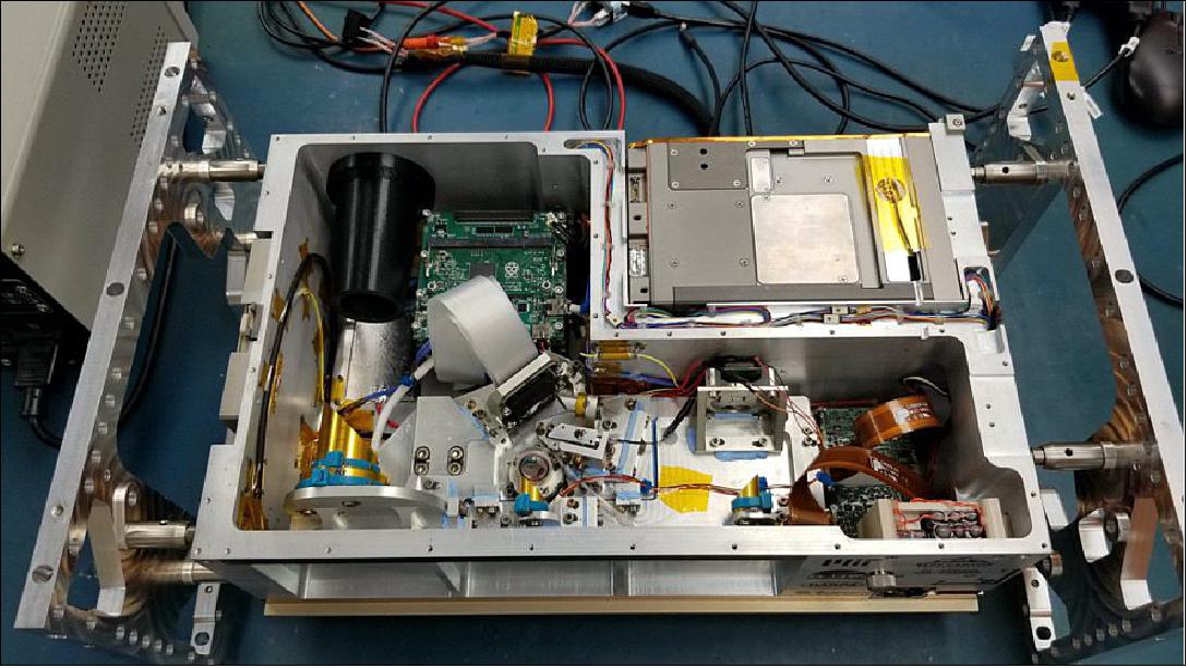
Thermal Considerations
Mismatches on the coefficient of thermal expansion of different components in an assembly can cause significant deformation and degrade the optical quality of the measurements when the temperature of the assembly changes. 14) To make sure the focal lengths and position adjustments of each payload component do not change with temperature variations along the satellite’s orbit, the OAP mirrors, the field mirror, and the major structural components are all made of the same material, aluminum.
To enhance the heat transfer between the structural components of the assembly that are kinematically mounted, thermal gap filler (Bergquist TGF3600) was added between the components to create a thermal interface where not much heat transfer would be possible otherwise. Figure 18 shows how the thermal gap filler was applied.
The three 6Al-4V titanium stand-off flexures that mount the payload into the satellite bus also perform two important roles in the thermal design on DeMi:
1) They give the optical bench the flexibility it needs to allow for thermal expansion and contraction during orbit without inducing undesired deformations onto the payload;
2) They allow the payload to be virtually thermally insulated from the bus, as the thermal conductivity of titanium is significantly smaller the that of aluminum, and the cross-sectional area of the standoffs is only of about 10-5 m2.
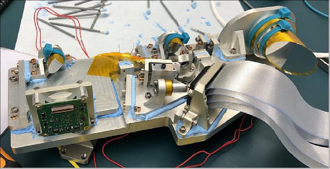
Thermal analysis was performed for the DeMi payload to assess the temperature ranges that components will experience during all stages of the mission. In order to maintain the thermoelastically induced misalignments as negligible, all optical elements and the bench are required to maintain their absolute temperature to 20°C ± 4°C during operational periods (up to 1000 seconds) and temperature gradients must be less than 2°C between optical components. The DeMi payload must maintain temperatures within the survival ranges of all components at all times. Two 2.5 W heaters were added to the payload to actively maintain the component temperature requirements. The heaters are located on the underside of the optical bench.
Using the bus provider (Blue Canyon Technologies) data, five cases were identified as bounding thermal cases and were modeled in Thermal Desktop: hot operational, hot storage, cold operational, cold storage, and commissioning. More details on the thermal model can be found in Allan et al. 201813. 15) It is important to note that for all cases examined, the DeMi payload components remained within their required temperature limits and the thermal stability during operational periods was found to be ±1°C across the optical bench and mounted optical components.
References
1) Gregory Allan, Ewan S. Douglas, Derek Barnes, Mark Egan, Gabor Furesz, Warren Grunwald, Jennifer Gubner, Christian Haughwout, Bobby G. Holden, Paula do Vale Pereira, Abigail J. Stein, Kerri L. Cahoy, ”The Deformable Mirror Demonstration Mission (DeMi) CubeSat: optomechanical design validation and laboratory calibration,” SPIE Astronomical Telescopes + Instrumentation, Austin, Texas, USA, 10 July 2018, arXiv:1807.02649 [astro-ph.IM], URL: https://arxiv.org/pdf/1807.02649.pdf
2) L. Pueyo, N. Zimmerman, M. Bolcar, T. Groff, C. Stark, G. Ruane, J. Jewell, R. Soummer, K. St. Laurent, J. Wang, D. Redding, J. Mazoyer, K. Fogarty, Roser Juanola-Parramon, S. Domagal-Goldman, A. Roberge, O. Guyon, A. Mandell, ”The LUVOIR architecture "A" coronagraph instrument,” Proceedings of SPIE Vol. 10398, 'UV/Optical/IR Space Telescopes and Instruments: Innovative Technologies and Concepts VIII)', 103980F, 13 September 2017, doi: 10.1117/12.2274654 , URL of abstract: https://doi.org/10.1117/12.2274654
3) Jennifer Gubner, ”Payload Configuration, Integration and Testing of the Deformable Mirror Demonstration Mission (DeMi) CubeSat,” Proceedings of the 32nd Annual AIAA/USU Conference on Small Satellites, Logan UT, USA, Aug. 4-9, 2018, paper: SSC18-VIII-05, URL: https://digitalcommons.usu.edu/cgi/viewcontent.cgi?article=4116&context=smallsat
4) ”Blue Canyon Technologies Selected by Aurora Flight Sciences to Provide CubeSat for DeMi Mission,” BCT, 15 August 2017, URL: http://bluecanyontech.com
/blue-canyon-technologies-selected-aurora-flight-sciences-provide-cubesat-demi-mission/
5) Paula do Vale Pereira, Bobby Holden, Rachel Morgan, Jennifer Gubner, Thomas J. Murphy,Christian Haughwout, Gregory Allan, Yinzi Xin, William Kammerer, Kerri Cahoy, Ewan Douglas, John Merk, Mark Egan, Gabor Furesz, ”Thermomechanical design and testing of the Deformable Mirror Demonstration Mission (DeMi) CubeSat,” Proceedings of the 34th Annual AIAA/USU Virtual Conference on Small Satellites, August 1-6, 2020, Logan, UT, USA, paper: SSC20-III-06, URL: https://digitalcommons.usu.edu/cgi/viewcontent.cgi?article=4723&context=smallsat
6) James Paul Mason, Matt Baumgart, Bryan Rogler, Chloe Downs, Margaret Williams, Thomas N. Woods, Scott Palo, Phillip C. Chamberlin, Stanley Solomon, Andrew Jones, Xinlin Li, Rick Kohnert, Amir Caspi, ”MinXSS-1 CubeSat On-Orbit Pointing and Power Performance: The First Flight of the Blue Canyon Technologies XACT 3-axis Attitude Determination and Control System,” Journal of Small Satellites, Vol. 6, Issue 3, pp. 651-662; December 2017, arXiv:1706.06967 [astro-ph.IM], URL: https://arxiv.org/pdf/1706.06967.pdf
7) Ewan S. Douglas, Gregory Allan, Derek Barnes, Joseph S. Figura, Christian A. Haughwout, Jennifer N. Gubner, Alex A. Knoedler, Sarah LeClair, Thomas J. Murphy, Nikolaos Skouloudis, John Merck, Roedolph A. Opperman, Kerri L. Cahoy,"Design of the Deformable Mirror Demonstration CubeSat (DeMi)." Proceedings of SPIE, Volume 10400, 'Techniques and Instrumentation for Detection of Exoplanets VIII,' 6-10 August, 2017, San Diego, California, edited by Stuart Shaklan, SPIE, 2017, p. 37. © 2017 SPIE, doi: 10.1117/12.2274430, URL: https://dspace.mit.edu/openaccess-disseminate/1721.1/115251
8) ”NASA Science, Cargo Heads to Space Station on Northrop Grumman Mission,” NASA Release 20-014, 15 February 2020, URL: https://www.nasa.gov/press-release
/nasa-science-cargo-heads-to-space-station-on-northrop-grumman-mission-0
9) Stephen Clark, ”Antares rocket lifts off from Virginia on space station cargo mission,” Spaceflight Now, 15 February 2020, URL: https://spaceflightnow.com/2020/02/15
/antares-rocket-lifts-off-from-virginia-on-space-station-cargo-mission/
10) ”Miniature Telescope Demonstration Focuses on Sharpening View of Distant Objects in Space,” DARPA News and Events, 28 July 2020, URL: https://www.darpa.mil/news-events/2020-07-28
11) Rachel E. Morgan, Ewan S. Douglas, Gregory W. Allan, Paul Bierden, Supriya Chakrabarti, Timothy Cook, Mark Egan, Gabor Furesz, Jennifer N. Gubner, Tyler D. Groff , Christian A. Haughwout, Bobby G. Holden, Christopher B. Mendillo, Mireille Ouellet , Paula do Vale Pereira, Abigail J. Stein, Simon Thibault, Xingtao Wu, Yeyuan Xin and Kerri L. Cahoy, ”MEMS Deformable Mirrors for Space-Based High-Contrast Imaging,” Micromachines 2019, Volume 10, 366, Published: 31 May 2019, URL: https://res.mdpi.com/d_attachment/micromachines
/micromachines-10-00366/article_deploy/micromachines-10-00366.pdf
12) Bobby Holden, Rachel Morgan, Gregory Allan, Paula do Vale Pereira, Warren Grunwald, Jennifer Gubner, Christian Haughwout, Abigail Stein, Yinzi Xin, Kerri Cahoy, Ewan Douglas, John Merk, Mark Egan, Gabor Furesz, ”Calibration and Testing of the Deformable Mirror Demonstration Mission (DeMi) CubeSat Payload,” Proceedings of the 33rd Annual AIAA/USU Conference on Small Satellites, August 3-8, 2019, Logan, UT, USA, paper: SSC19-WKIV-03, URL: https://digitalcommons.usu.edu
/cgi/viewcontent.cgi?article=4370&context=smallsat
13) Christian Alexander Haughwout, ”Electronics development for the Deformable Mirror Demonstration Mission (DeMi),” Master's Thesis, MIT, Department of Aeronautics and Astronautics, 2018. https://dspace.mit.edu/bitstream/handle/1721.1/120438/1084654009-MIT.pdf?sequence=1&isAllowed=y
14) Paula do Vale Pereira, Matthew T. Hunwardsen, Kerri L. Cahoy, ”Characterization of laser thermal loading on microelectromechanical systems-based fast steering mirror in vacuum,”Optical Engineering, 59(5), 056109 (20 May 2020). https://doi.org/10.1117/1.OE.59.5.056109
15) Gregory Allan, Ewan S. Douglas, Derek Barnes, Mark Egan, Gabor Furesz, Warren Grunwald, Jennifer Gubner, Christian Haughwout, Bobby G. Holden, Paula do Vale Pereira, Abigail J. Stein, Kerri L. Cahoy, ”The Deformable Mirror Demonstration Mission (DeMi) CubeSat: Optomechanical Design, Validation, and Laboratory Calibration,” Proceedings of SPIE, Volume 10698, 'Space Telescopes and Instrumentation 2018: Optical, Infrared, and Millimeter Wave; 1069857 (21 August 2018),' https://doi.org/10.1117/12.2314192, SPIE Astronomical Telescopes + Instrumentation, 2018, Austin, Texas, United States
The information compiled and edited in this article was provided by Herbert J. Kramer from his documentation of: ”Observation of the Earth and Its Environment: Survey of Missions and Sensors” (Springer Verlag) as well as many other sources after the publication of the 4th edition in 2002.Comments and corrections to this article are always welcome for further updates (eoportal@symbios.space).
Spacecraft Launch Mission Status Payload Overview Laboratory validation References Back to top