DeOrbitSail
Non-EO
ESA
DLR
Uni of Stellenbosh
Quick facts
Overview
| Mission type | Non-EO |
| Agency | ESA, DLR, Uni of Stellenbosh, NASA-JPL |
| Launch date | 10 Jul 2015 |
| End of life date | 13 Nov 2015 |
DeOrbitSail (DOS) Nanosatellite Mission
Overview Spacecraft Launch On-orbit Operations and Milestones Mission Status Data Products References
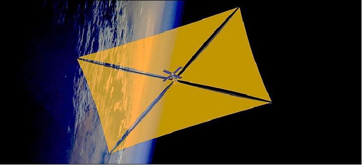
The DeOrbitSail project is a low cost end-to-end space mission, which will demonstrate satellite deorbiting through the deployment of an ultra light 5 m x5 m sail, which will fit in a 3U CubeSat nanosatellite platform. The DeOrbitSail is an EU-funded (European Union, FP7 project) space mission to demonstrate the ability to deorbit space junk using a low cost, ultra light solar sail as a drag sail, bringing debris closer to Earth so they can eventually burn up through friction in Earth's atmosphere. 1) 2) 3) 4) 5) 6) 7)
25 Year Deorbiting Requirement 8) 9)
Historical practice of abandoning satellites at the end of their lifetime has left 8,500 tons of space waste in LEO (Low Earth Orbit). In the future, this practice must change. Increasingly, space debris poses a risk for spacecraft. Hundreds of old satellites and thousands of pieces of space junk orbit Earth. Such debris collide, which in turn increases the amount of debris, as pieces of old satellites break of when hit by pieces of other retired spacecraft. Indeed, without a change of practice and the establishment of effective systems for safe de-orbiting of spacecraft at the end of their lifetime, it is estimated that the number of debris particles will grow with a growth rate in the order of 5 %/year, a percentage which would raise over time as the number of possible collisions increase.
• Orbital debris mitigation guidelines have been debated in great detail in the space community.
• In 2002, IADC (Inter-Agency Space Debris Coordination Committee) completed a set of debris mitigation guidelines agreed to by the space agencies of the world. In Feb. 2003, these guidelines were presented to UNCOPUOS (United Nations Committee on Peaceful Uses of Outer Space) for review and approval.
• In February 2007 and after a multi-year effort UNCOPUOS-STS adopted a set of space debris mitigation guidelines which recommended a 25 year deorbit requirement from LEO. 8) 9)
• The guidelines were accepted by UNCOPUOS in June 2007 and endorsed by the United Nations in January 2008.
• To become the law in many countries in Europe and elsewhere.
• About 90% of the roughly 1300 operational satellites currently (2013) in orbit are either in LEO (300-2000 km altitude range) or in GEO (~36000 km altitude). In LEO, the satellites and the orbital debris are quite widely scattered in terms of altitude, inclination and ascending node. This, in combination with the fact that orbital speeds are considerably higher than in the GEO case, makes both the amount of crossings and the relative velocities of the bodies during these crossings very high on average.
• Another critical issue is that ISS (International Space Station) operations are performed at low LEO altitudes, making it essential that the risk of collision is minimized to the greatest possible extent in this area for safety of human spaceflight.
The UNCOPUOS guidelines, although important, only address active satellites currently in orbit and future launches. Despite the serious threat posed by existing orbital debris, which regularly endanger active operational satellites and manned operations, they were not addressed by these international initiatives.
There is no single or ‘silver bullet solution' solution for debris removal/mitigation.
The Deorbitsail project is a collaboration to build a 3U CubeSat sized satellite with a deployable sail that will demonstrate rapid deorbiting. The deorbiting capability of the Deorbitsail satellite is due to solar radiation pressure and to increased aerodynamic drag from the large surface area of the deployed sail in LEO (Low Earth Orbit).
DeorbitSail is a demonstrator mission: its purpose is to raise the technology readiness level of a deployable sail system. The Deorbitsail team hopes that an increase in TRL will make this low-mass, low-energy deployable sail an attractive deorbiting subsystem for future spacecraft, and therefore mitigate the problem of space debris.
It is estimated that the Deorbitsail system will be suitable for deorbiting satellites of 20 -500 kg from orbits below 1000 km within the guideline time of 25 years.
No | Institution | Country | Main role in the project |
1 | SSC (Surrey Space Center), Guildford | UK | Coordinator; Sail Mission requirements; sail technology survey; solar sail mechanism/deployment; flight model functional testing; management |
2 | JPL/Caltech, Pasadena, CA | USA | Solar Sail modelling and simulation; finite element analysis |
3 | Astrium SAS, Toulouse | France | Solar Sail materials, Solar Sail testing |
4 | DLR (German Aerospace Center), Braunschweig | Germany | Development, manufacturing and test of deployable gossamer booms |
5 | Stellenbosch University, Stellenbosch | South Africa | Spacecraft attitude determination and control |
6 | University of Patras, Patras | Greece | Cubesat (satellite) CF structure, thermal analysis |
7 | Athena SPU (Space Program Unit), Athens | Greece | Satellite electronics,testing, dissemination and communications |
8 | METU (Middle East Technical University), Ankara | Turkey | Sail boom controls/damping |
9 | SSTL (Surrey Satellite Technology Ltd.), Guildford | UK | Flight operations, flight data analysis, ground station support |
10 | ISIS (Innovative Solutions In Space, BV), Delft | The Netherlands | Satellite subsystems (power, RF), integration, flight campaign and launch vehicle integrator |
Objectives of the mission: 10)
• Demonstrate deorbiting
• Demonstrate deployment of 25 m2 solar sail
• Implement a 3-axis active ADCS to align the sail to the orbit plane ⇒ minimum drag in LEO
• Measure solar force over a minimum 1 year period
• Based on COTS, 3U Cubesat
• Funded by the European Commission (2011)
• Budget of 2.8 million Euros including launch
• Framework 7 program –FP7
• Difference to CubeSAIL: Carbon Fiber booms/deployment system designed by DLR
• Fit in a 3U Cubesat nanosatellite, launch in 2014.
Research goals: DeorbitSail is not exclusively a technology demonstration mission; there are a number of academic and analytic research goals. Among these is the validation of models for deorbiting effectiveness. Analytic tools that consider the shape of the spacecraft and sail, functioning of the attitude control system, and probable interactions with the existing space debris environment have been developed at Stellenbosch University and the Surrey Space Centre.
Spacecraft
Deorbitsail is a small satellite mission that will launch and deploy a 5 m x 5 m, four-quadrant sail to demonstrate deorbiting. The spacecraft will be based on a 3U CubeSat standard structure, with dimensions close to 10 cm x 10 cm x 34 cm. Deorbitsail will be a satellite with a mass of 7 kg, but with power, communications, attitude control and data handling components, in addition to its densely packed sail and deployment system. The sail will be able to change the satellite's orbit through drag and solar radiation pressure.
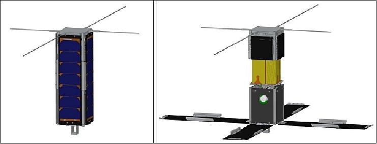
Legend to Figure 2: Left: At the base of the spacecraft is a small stand to separate the magnetometer from the rest of the spacecraft. Right: From bottom to top, the satellite has three sections: The electronics bus (Fig. 6), the sail storage area (with packed sails, which will be clear yellow Kapton membranes), and the boom deployer.
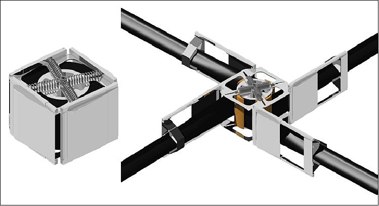
The bottom 1U of DeorbitSail houses the majority of the electronics necessary for functioning as a satellite. Four deployable solar panels are connected at the base of the structure; these will each support six solar cells. The panels will initially lie flat on the long sides of the satellite, as depicted in Figure 3 (left), to improve the power profile during the initial tumbling phase. The solar panels will later deploy to lie in a single plane.
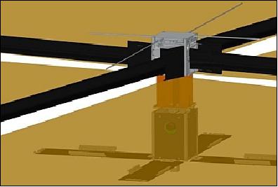
Above the electronics stack is the sail storage area, where the folded sail will be stowed. A double Z-fold will be used to pack the sail membrane into this limited space. The sail is pulled from the sail storage area by four carbon fiber booms; their deployed appearance is shown in Figure 3. Above this storage area is the boom deployer. The deployer, which contains the four booms that will deploy and support the sail, occupies approximately 1U of volume.
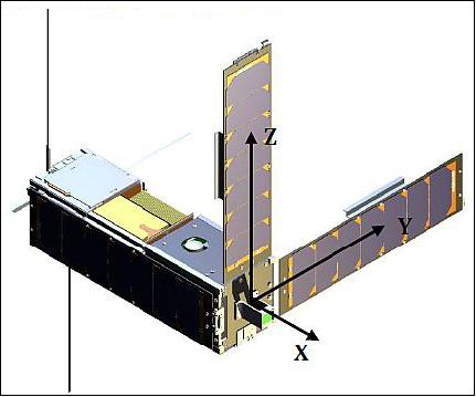
The ADCS body coordinate frame is shown in Figure 4 with partially deployed solar panels. The X-body axis will be pointed towards the nominal velocity vector and the Z-body axis towards nadir when the satellite is 3-axis stabilized before sail deployment. 11)
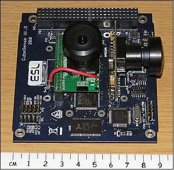
The ADCS bundle as shown in Figure 5, consists of the following modules (from bottom to top), CubeComputer, a 32-bit radiation tolerant CubeSat OBC for satellite housekeeping and executing the ADCS software, CubeCoil, a magnetorquer coil for the X-body axis, CubeSense, a sun and nadir camera sensor with 180° field of view, CubeAim, with the Y- and Z-axis magnetorquers mounted on the PCB and acting as a sensor interface to 10 coarse sun sensors, a 3-axis magnetometer and a MEMS Y-rate sensor. CubeAim also contains the drive electronics for the magnetorquers, Y-wheel, stepper motors of the Y/Z sail translation stage and the sail deployment motor. The CubeWheel momentum wheel is the final component shown to the right front with its spin axis aligned to the Y-body axis to give inertial stiffness to the body roll (X) and yaw (Z) axes. 12)
Sensors and actuators | Type | Range/FOV | Accuracy (rms) |
Magnetometer | 3-axis MagR | ± 60 µT | < 40 nT |
Sun sensor | 2-axis CMOS | Hemisphere | < 2º peak |
Nadir sensor | 2-axis CMOS | ± 45º | < 2º peak |
Coarse sun | 10 Photodiodes | Full sphere | < 10º |
Rate sensor | MEMS | ± 80º/s | < 0.05º/s |
Y-momentum pitch wheel | BDC motor | ± 40 mNms | < 0.05 mNms |
Magnetorquers | Ferro-magnetic rods & air coil | ± 0.2 Am2 | < 0.002 Am2 |
Y/Z translation stage for sail | 2-axis stepper motors with 64:1 gearbox | ± 35 mm | < 0.01 mm per step |

Figure 6 shows the DeorbitSail electronics stack. The majority of the space for electronics is occupied by the ADCS, a three-axis-stabilized system designed by Stellenbosch University and customized for DeorbitSail. Using a combination of coarse sensors and cameras, this system will determine the satellite attitude and tumbling rates. Attitude is controlled with three types of actuators: a set of three magnetorquers, a single momentum wheel controlling pitch, and a translation stage. The translation stage, located between the electronics bus and the sail storage area (Figure 2 right) is an experimental technology on this mission and not strictly required to stabilize the spacecraft. By shifting the alignment of the center of mass (located in the electronics bus) relative to the center of pressure (located on the deployable sail), small adjustments to the pitch and yaw of the spacecraft can be made without a propulsion system or additional momentum wheels.
While the ADCS (Attitude Determination and Control Subsystem) has been developed as part of the DeorbitSail project, the remainder of the DeorbitSail bus electronics is composed of off-the-shelf Cubesat parts. These are summarized in Table 4.
Item | Model |
EPS (Electrical Power Subsystem) | GOMspace NanoPower P31u |
VHF/UHF radio | ISIS TRXUV |
OBC (Onboard Computer) | CubeComputer |
Antenna | ISIS deployable Cubesat antenna |
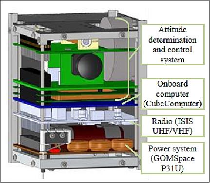
ADCS (Attitude Determination and Control Subsystem): The ADCS processing will be carried out by a software task running on the OBC . The estimation and control loop will execute at a rate of 1 Hz. It will make use of sensor data from the following sensors: 13)
• 3-axis resistive magnetometer
• Optical sun- and nadir sensors
• 3-axis MEMS gyroscope
• Coarse sun sensing using 10 photodiodes.
Use of a combination of magnetic torquer rods and sail center-of-pressure to center-of-mass control for actuation. The latter makes use of a translation stage between the satellite bus and the sail attachment. Translating the sail center-of-pressure with respect to the satellite bus changes the torque generated by the sail (both aerodynamic and solar radiation pressure) and can thus be used to control the attitude of the sail.
Launch
The DeorbitSail demonstration nanosatellite was launched as a secondary payload on July 10, 2015 (16:28:00 UTC) on a PSLV-C28 vehicle (XL configuration) of ISRO from SDSC (Satish Dhawan Space Center) SHAR, located on the south-east coast of India.
The primary payload on this flight was the DMC-3 constellation (3 minisatellites, each of 447 kg), owned and operated by DMCii (DMC International Imaging Ltd.) of Guildford, Surrey, UK. 14) 15)
Orbit: Sun-synchronous orbit, altitude = 650 km, inclination = 97.8º, LTAN (Local Time on Ascending Node) = 10:30 hours. The three DNC-3 spacecraft will be evenly spaced in the same orbital plane with daily revisit times which is crucial for change detection, disaster monitoring and response planning, and essential for acquiring cloud-free imagery.
The secondary payloads were:
• CBNT-1, a technology demonstration Earth Observation (EO) microsatellite (91 kg) of by SSTL.
• DeOrbitSail, a demonstration nanosatellite (7 kg) of SSC (Surrey Space Centre). The nanosatellite will be deployed from ISIPOD ((Innovative Systems in Space Cubesat Deployer). 16)
With a total launch mass of 1440 kg, this represents the heaviest commercial launch so far for the organization. ISRO has built a circular Launcher adapter (L-adapter) and a triangular deck called Multiple Satellite Adapter-Version 2 (MSA-V2) exclusively for the purpose.
On-orbit Operations and Success Milestones
Like most Cubesats, DeorbitSail does not include any substantial redundant systems. The operational lifetime is expected to be a few months. It is also true that many Cubesats carry a generally higher risk of failure at every stage than conventionally built spacecraft. It is therefore valuable to have a concept of operations that gathers data as early as possible and recognizes many intermediate stages of success.
DeorbitSail has a substantial advantage in that the most direct proof of its success will be encoded in its TLEs (Two-Line Elements), which are a type of orbital data generated and provided by NORAD. The TLEs will indicate the altitude of the orbit as it is gradually lowered. Complete mission success will be achieved when the TLEs indicate that the orbit has rapidly decayed to demise in the atmosphere.
Between launch and demise, there are many measurable milestones of partial success. Unlike the long-term altitude decay, which is confirmed by third-party observations, all these intermediate measures will require a fully functional communications system. The success milestones begin with the functioning of the ADCS.
The first phase of operations is to identify the tumbling rates of the spacecraft based on readings from the six coarse sun sensors and one magnetometer. Detumbling will begin after confirmation that the ADCS estimator is functioning as expected. DeorbitSail will then detumble to a Y-Thompson spin and ADCS readings will confirm that the system has functioned correctly for this phase, as well as provide data to validate the ADCS models.
After achieving a Y-Thompson spin, the solar panels will deploy and the fine attitude determination system will be activated. Fine attitude determination is performed with a sun camera and a horizon camera. A new mode of attitude control will despin from the Y-Thompson spin, finally producing a stably pointed spacecraft.
At this point, the ADCS system will have successfully stabilized DeorbitSail in an orientation suitable for sail deployment. Reaching this state is a significant milestone and success for the ADCS design. Depending on the launch order of certain upcoming Cubesats (e.g., SSC's CubeSail), it is likely to be the first in-orbit demonstration of the CubeComputer with this ADCS algorithm on a Cubesat, the first demonstration of the CubeAIM system, and the second use of CubeSense after STRaND-1. 17) Elements of the ADCS hardware have flown before in various forms, including in the ADCS of South Africa's SumbandilaSat 18), but DeorbitSail will be the first demonstration of this Cubesat-specific ADCS.
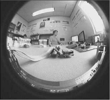
In the next phase of operations, the sail will be deployed. The horizon camera will take a black-and-white photograph of the deployed sail. As a result of the camera location, this picture will include somewhat less than half of the sail. Incomplete deployment (which may be correctable) and some forms of sail failure will be diagnosable from this image. Receipt of an image showing a completely deployed sail is the second major success milestone. This will be the measure of success for the deployment system.
With the sail deployed, the satellite will move into its extended operations phase. In this phase, there are three substantial demonstration tasks remaining:
1) the effectiveness of the COM-COG offset system in attitude control of a sail
2) the long-term operations of the sail
3) the effectiveness of a drag sail and its agreement with models in deorbiting of a satellite.
Effectiveness of the translation stage can be evaluated with the outputs of the ADCS, and as long as the camera and communications systems remain operational, more pictures can be taken of the sail. If communications are lost at any point after sail deployment, the effectiveness of the sail (and perhaps the continued functioning of the ADCS) can be evaluated by the TLEs.
Mission Status
• Nov. 13, 2015: After 4 months of operations, the satellite is healthy and stable, although unfortunately the operations team has not been able to meet all of the mission objectives. Initial contact with the satellite was established relatively smoothly and the team received a lot of good data, both through the ground station at Surrey, but also via the network of radio amateurs. 19)
Note: This status report of the DeOrbitSail mission was provided to AMSAT-UK by Chris Bridges of SSC (Surrey Space Centre), including all following bullets.
- The team achieved a power stable state early on, with good communications (uplink and downlink) established within the first few days after launch. The team deployed the solar panels successfully, and managed to return to a good and stable power state after deployment.
- The ADCS has been challenging from the start, and continues to be challenging — the team has struggled to accurately determine the satellite tumble rate and get it under control (more detail on that is included below). The satellite experienced initially very high spin rates for various reasons, including some inherent design/magnetic characteristics which have become apparent.
- Despite many attempts, the team has not been able to deploy the sail, and having recently thoroughly analyzed and investigated the possible causes, mission events and ground test data and history, the team is now reaching the conclusion that achieving successful sail deployment is very unlikely.
- The aim now is to exercise and exploit the parts of the satellite that are working, and gain more confidence and experience with the SU ADCS system, the ISIS TRXUV and solar panels, and the SSC SDR groundstation and database tools to explore better the interaction of the panel circuitry with the attitude stabilization. That will allow us to improve our performances in the next missions.
• On Aug. 15, 2015, the first attempt for sail deployment was performed, the command was sent and the acknowledgement from the S/C was received, but no current was drawn from the boom deployer motor. Multiple experiments were performed to try and determine the cause of sail deployment failure.
- At this point, after a thorough investigation, the most plausible hypothesis and justification seems to be a physical disconnection of the motor cables. (Note that after the vibration test, it wasn't possible to physically inspect the connection due to the design itself of the S/C).
- The simulations showed that with the actual configuration (deployed solar panels, undeployed sail) the decay time should be 20 years circa.
• More than a month after the launch the satellite was really healthy, power safe and with great communicatins through the newly developed SDR (Software Defined Radio) and database backend operations. Although the stabilization wasn't achieved even with the solar panel deployment, at one month from the launch, the team decided to proceed with the sail deployment.
- This decision was agreed with DLR that confirmed that tumbling rates were no issue for the sail deployment, because the Moments of Inertia increase rapidly slowing down the tumble rate. DLR has performed a deployment test on Gossamer while tumbling before coming to this opinion.
• Although the spin up of the S/C was much higher than expected and saturated the sensors, the SU(Stellenbosch University) simulations and the available data suggested a large Z-spin rate on DOS which was confirmed by the B-field and MEMS magnetometry measurements. To induce a bigger difference in the MoI (Moments of Inertia) of the two non-longitudinal axes, the decision was taken to deploy the solar panels. This operation was performed the 10th of August.
• After the launch on the 10th of July, and the first week in orbit, with a power safe and healthy satellite, the operation passed from the LEOP phase to the ADCS Commissioning phase. This second phase was estimated to last between three and four weeks; this proved to be optimistic.
Data Products
The following data products are anticipated, and will be logged in this order:
• Detumbling and stabilization phase:
- Initial tumbling rates
- Progression of tumbling rates to Y-Thompson spin
- Progression from Y-Thompson spin to stable pointing.
• Sail deployment phase:
- Deployed sail image (Figure 9).
• Extended operations:
- Progression of attitude with actuation of the translation stage
- TLEs during deorbiting.
References
1) http://www.deorbitsail.com/index.html
2) Vaios Lappas, S. Pelleggrino, H. Guenat, M. Straubel, H. Steyn, V. Kostopoulos, E. Sarris, O. Takinalp, S. Wokes, A. Bonnema, "DeOrbitSail: De-Orbiting of Satellites using Solar Sails," , 2nd International Conference on Space Technology (ICST), Athens, Greece, Sept. 15-17, 2011
3) Vaios Lappas, "Gossamer Systems for Satellite Deorbiting: The CubeSail and DeorbitSail Space Missions," AIAA SDM (Structural Dynamics and Materials) conference, Honolulu, HI, USA, April 23-26, 2012, URL: https://web.archive.org/web/20151029132833/https://www.surrey.ac.uk/ssc/research/space_vehicle_control/deorbitsail/files/gsf_keynote_2012.pdf
4) Vaios J. Lappas, Olive R. Stohlman, Lourens Visagie, Theodoros Theodorou, Juan M. Fernandez, George Prassinos, "Deorbitsail: flight-testing a deorbiting system," Proceedings of the 64th International Astronautical Congress (IAC 2013), Beijing, China, Sept. 23-27, 2013, paper: IAC-13-A63.4.6
5) W. H. Steyn, "FP7: Deorbit Sail Project," April 18, 2011, URL: http://tinyurl.com/osm48wb
6) "DeorbitSail: A Spacecraft Mission to deploy sails in Space," URL: http://www.athena-spu.gr/projects/DeOrbit
7) Olive R. Stohlman, Vaios Lappas, " Deorbitsail: a deployable sail for de-orbiting ," 54th AIAA/ASME/ASCE/AHS/ASC Structures, Structural Dynamics, and Materials Conference, Boston, MA, USA, April 8-11, 2013
8) "Report of the Committee on the Peaceful Uses of Outer Space," General Assembly Official Records Sixty-second session Supplement No. 20 (A/62/20), 2007, URL: http://www.unoosa.org/pdf/gadocs/A_62_20E.pdf
9) "Space Debris IADC Assessment Report for 2010," IADC-11-04, April 2013, URL: http://www.iadc-online.org/Documents/IADC-2011-04,%20IADC%20Annual%20Report%20for%202010.pdf
10) "A promising approach for deorbiting retired spacecraft," ESA, Dec. 17, 2013, URL: https://artes.esa.int/news/promising-approach-deorbiting-retired-spacecraft
11) Olive R. Stohlman, Juan M. Fernandez, Vaios J. Lappas, Martin Hillebrandt, Christian Hühne, Marco Straubel, "Testing of the Deorbitsail drag sail subsystem," 54th AIAA/ASME/ASCE/AHS/ASC Structures, Structural Dynamics, and Materials Conference, Boston, MA, USA, April 8-11, 2013
12) Willem Herman Steyn, Hendrik Willem Jordaan, "An active Attitude Control system for a Drag Sail Satellite," Proceedings of the 66th International Astronautical Congress (IAC 2015), Jerusalem, Israel, Oct.12-16, 2015, paper: IAC-15-B4.6A.1
13) "DeOrbitSail, Attitude determination and control system (ADCS)," University of Surrey, Sept. 23, 2013, URL: http://www.surrey.ac.uk/ssc/research/space_vehicle_control/deorbitsail/science_and_tech/
14) "PSLV-C28 / DMC3 Mission," ISRO, URL: http://www.isro.gov.in/launcher/pslv-c28-dmc3-mission
15) "SSTL announces the successful launch of the DMC3/TripleSat Satellite Constellation," SSTL, July 10, 2015, URL: https://www.sstl.co.uk/media-hub/latest-news/2015/sstl-announces-the-successful-launch-of-the-dmc3-triplesat-constellation
16) http://www.isispace.nl/cms/
17) C. P. Bridges, S. Kenyon, C. I. Underwood, M. N. Sweeting, "STRaND: Surrey Training Research and Nanosatellite Demonstrator," 1st IAA Conference on University Satellite Mission and CubeSat Workshop, Rome, Italy, January 24-29, 2011
18) Sias Mostert, Herman Steyn, Hendrik Burger, Helena Bosman, "Sumbandilasat—An operational technology demonstrator," Acta Astronautica, 2008, Vol. 63, pp. 1273-1282, URL: http://staff.ee.sun.ac.za/whsteyn/Papers2/ActaAstro_3141.pdf
19) "DeOrbitSail Update and Initial Camera Image," AMSAT-UK, Nov. 13, 2015, URL: http://amsat-uk.org/2015/11/13/deorbitsail-update-and-initial-camera-image/
The information compiled and edited in this article was provided by Herbert J. Kramer from his documentation of: "Observation of the Earth and Its Environment: Survey of Missions and Sensors" (Springer Verlag) as well as many other sources after the publication of the 4th edition in 2002. Comments and corrections to this article are always welcome for further updates (eoportal@symbios.space).
Overview Spacecraft Launch On-orbit Operations and Milestones Mission Status Data Products References Back to top