Genesis (Solar-Wind Sample Return Mission)
Non-EO
NASA
NASA-JPL
Science
Quick facts
Overview
| Mission type | Non-EO |
| Agency | NASA, NASA-JPL |
| Launch date | 08 Aug 2001 |
| End of life date | 08 Sep 2004 |
Genesis (Solar-Wind Sample Return Mission)
Genesis is a NASA mission (Discovery Program) into a halo orbit around the Lagrangian point L1 (outside of the Earth's magnetosphere, L1 is located 1.5 million km from Earth in the direction toward the sun). The objective is to monitor the solar wind and to collect particles of the solar wind by ion implantation into the collector materials for a duration of two years, and to return these samples for isotopic and chemical analysis in terrestrial laboratories. - The outer portion of the sun is believed to reflect the bulk composition of the original solar nebula. One way to measure the composition of the outer portion of the sun is to analyze the solar wind. The science objectives are:
• To obtain precise measures of solar isotopic abundances. Measurement of isotopic compositions of oxygen, nitrogen, and noble gases. These data enable scientists to better understand the isotopic variations in meteorites, comets, lunar samples, and planetary atmospheres.
• To obtain greatly improved measures of solar elemental abundances
• To provide a reservoir of solar matter for 21st century science research, eliminating the need for future solar wind sample return missions.
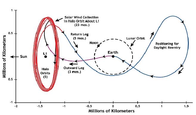
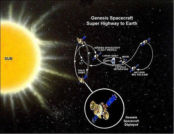
Overall mission scenario: At L1, Genesis unfurls its collector arrays and begins collecting particles of the solar wind that imbed themselves in specially designed high purity wafers. After two years, the sample collectors are being re-stowed and returned to Earth for a mid-air recovery of the sample return capsule. The samples are being stored and cataloged under ultra-pure clean room conditions and made available to the world scientific community for study.
The Genesis mission is managed by NASA/JPL. The spacecraft and the SRC (Sample Return Capsule) were developed and built at LMA (Lockheed Martin Astronautics), Denver, CO. Other project partners are: LANL (Los Alamos National Laboratory - development of the sample concentrator and two solar wind monitors); NASA/MSFC \[with AAIF (Advanced Analytical Instrument Facility)\]; JSC (Johnson Space Center) - providing the class 10 cleanroom for assembly and post-flight disassembly of the solar wind collectors, as well as curation of the returned samples (Note: “class 10” refers to the fact that only 10 particles of contaminant per cubic meter are allowed). The head of the project is Principal Investigator (PI) Donald Burnett of the California Institute of Technology. Approximately 18 science co-investigators are from various institutions and countries, including Japan, Switzerland, and the U.K.
Note: In the initial project phase (1995) the solar-wind sample return mission was called “Suess-Urey.” It was renamed to “Genesis” in 1996 after the completion of Phase A.
Spacecraft
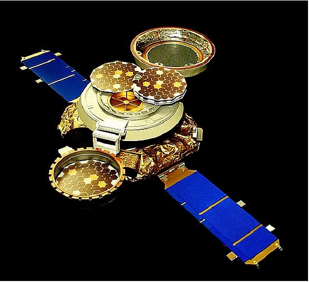
The Genesis spacecraft is sun-oriented and spin-stabilized with two fixed solar arrays. The spin rate on station is one revolution in 37.5 seconds. The S/C has three major components: the platform, the SRC (Sample Return Capsule), and the payload. The platform structure employs a truss of graphite-polycyanate composite tubes with titanium end-fittings. The truss supports a composite honeycomb-reinforced deck that forms a platform for equipment mounting. The SRC is attached to the platform via three bipod struts. The size of the platform, 1.7 m diameter x 0.5 m height, is dictated by the SRC diameter of 1.5 m, selected in turn to maximize the payload collector area. The deployed length of the S/C is 7.9 m. Power of 202 W (EOL) is provided by two non-articulated solar arrays (each of 1 m2); in addition, two batteries provide energy during trajectory correction maneuvers (capacity of 448 Whr at 100% SOC (state of charge) and 313 Whr at 70% SOC). The C&DH (Command and Data Handling) subsystem uses a RAD 6000 processor (redundant processors, uplink/downlink, I/O and payload/attitude control functions. A propulsion subsystem with monopropellant hydrazine thrusters (78 kg of propellant) is used for the cruise phase from Earth to the halo orbit at L1. The S/C mass is 494 kg, the launch mass (including propellant) is 636 kg.
The ACS (Attitude Control Subsystem) provides spin attitude and rate knowledge, and open loop thruster control. Attitude sensors and estimation algorithms are used to provide knowledge that is then used by thruster control algorithms to change spin rate, precess the spacecraft angular momentum vector, provide trajectory corrections through delta-V implementation, and for contingency operations. There are three attitude sensor types: DSS (Digital 2-axis Sun Sensor), SSS (Spinning Sun Sensor) and ST (Star Tracker). Redundancy and cross-strapping are used to assure reliability. Each star tracker has a FOV of 33.5º x 23.5º. Star images are captured on a CCD. Primary attitude knowledge is provided by an attitude control algorithm called Spin Track. Spin Track uses individual star measurements from the star tracker, and a forward-facing sun sensor to determine a given star's brightness, spin-phase angle, and off-sun angle. The spacecraft spin rate on station is 1 revolution in 37.5 seconds. 1) 2) 3) 4)
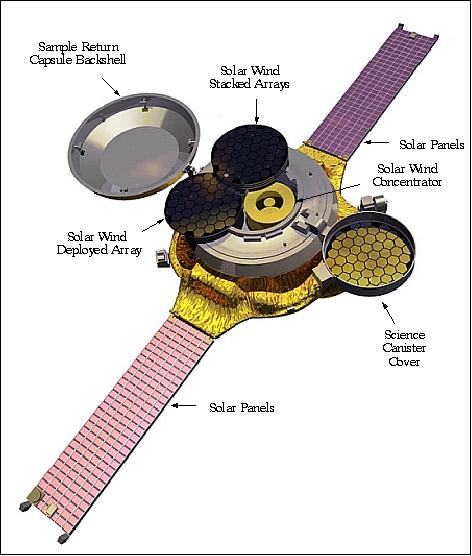
Width of spacecraft deck | 2.3 m |
Solar panel span (longest dimension of the spacecraft) | 7.9 m |
Diameter of Sample Return Capsule (SRC) | 1.5 m |
Diameter of Science Canister | 0.97 m (longest distance across) |
Height from bottom to top of SRC | 1.31 m |
Spin rate on station | One revolution every 37.5 seconds |
Mass of spacecraft | 494 kg (dry mass), 636 kg (wet mass) |
Spacecraft power | 202 W average (EOL), 254 W max |
Propulsion system | Blowdown monopropellant (hydrazine) with helium pressurant |
RF communications: An on-board recorder of 1 Gbit storage capacity is provided. The uplink and downlink is in S-band at 15 kbit/s, 120 bit/s during cruise phase). The low data rate of the solar wind monitors at <1 kbit/s allows infrequent (weekly) contacts with the S/C via DSN. The S/C communication subsystem has two transponders, four LGA (Low Gain patch Antennas) and MGA (Medium Gain Antenna). The LGA are located on the solar arrays.
Launch
The launch of the Genesis spacecraft took place Aug. 8, 2001 on a Delta-7326 vehicle from Cape Canaveral Air Station, FLA.
Orbit: A halo orbit into the Lagrangian point L1, balanced gravitationally between the sun and the Earth. L1 is located about 1.5 million km from Earth, amounting to 1/100 the distance from Earth to the sun. The S/C takes approximately 3 months to arrive at the halo orbit insertion, after which it makes 4 loops about the L1 point over a period of about 2 years. The spacecraft then moves out of the halo orbit on a trajectory taking it through the L2 point on the anti-sunward side of the Earth in order to position it for a daytime reentry.
Payload Complement
The Genesis mission has two primary instruments, a) collector arrays which passively collect solar wind samples and b) the concentrator. Both the collector arrays and the concentrator contain suites of ultra-high purity target materials, each of which is tailored to enable the analysis of a different element family. In addition, there are two solar wind monitors (electron and ion spectrometers) to measure and classify the solar wind. 5)
Collector Arrays
A set of four panels (comprised of individual hexagon collectors), each capable of separate deployment to sample the different kinds of solar wind.
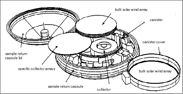
Each collector has the form of a flat pan with a diameter of 73 cm (collecting area of 3500 cm2). In L1 halo orbit, after the canister lid opens, the stack of four arrays is rotated away from the canister, exposing the concentrator inside the canister. The topmost two of the four collector arrays, along with the array and the canister lid, are always exposed to the solar wind flux. The two lower collectors in the stack are exposed one at a time, depending on which of the solar wind regimes is being detected by the solar wind monitors. The collector retraction mechanism is inertial to the canister, consisting of a set of motors driving concentric cylindrical actuators which rotate the arrays individually about a common axis. - Each of the four collector arrays is composed of 55 hexagonal collector wafers, made of different materials and of ultra-high purity. The majority of the wafers are made of silicon; they are about 0.5 mm thick and 10 cm (point-to-point) hexagonal shape. Other wafer materials are aluminum and gold foils. The temperature of all collector arrays is kept at < 200 K.
Solar Wind Concentrator
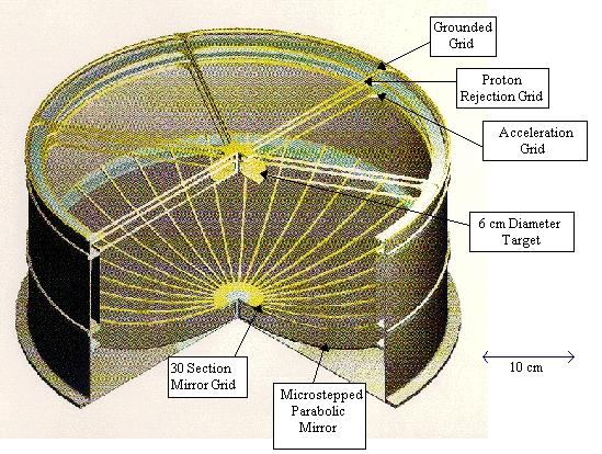
The assembly consists of an electrostatic mirror which enhances the density of C, N and O ions from the solar wind to provide better signal-to-background ratios for these elements. An ion concentration by a factor of >20 is achieved, focusing them onto a target of 6 cm in diameter. The basic design is illustrated in Figure 6. Solar wind ions enter from the top through a series of three high transmission grids. The topmost grid is maintained at ground potential so that potentials inside the concentrator do not extend outside of it or affect the trajectories of particles prior to their entry. The next grid is biased at a variable positive high voltage. This voltage is set such that the bulk of the solar wind protons are rejected while essentially all of the heavier ions are transmitted. The third grid is mounted to a metal structure which completely encapsulates the inner region of the concentrator and is maintained at a constant negative high voltage of -8 kV. The target is a six centimeter disk mounted onto a structural spider that is in the plane of, and supports, the third (-8 kV) grid. 6) 7)
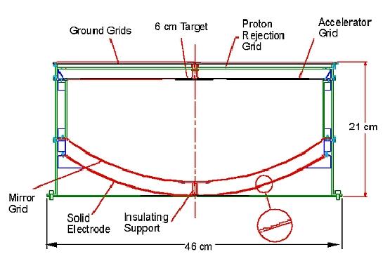
Heavy ions enter through the grounded grid, pass through the proton suppression grid, and are accelerated into the interior region by -8 kV on the accelerator grid. They are then reflected between the mirror grid and the solid electrode, and embedded deep into the target. The inset shows micro-machined steps in the electrode which serve to reflect light and heat back out into space rather than concentrating it also onto the target. Energetic ions from the sun penetrate into the collector materials and remain implanted.
The solar wind collection system is built around collector arrays which are deployed from the SRC (Sample Return Capsule) which faces the sun.
Solar-Wind Monitors
A pair of solar wind monitor instruments (electron spectrometer and ion spectrometer) are used to detect the solar wind regime. These monitors determine the type of prevalent solar wind being measured \[types: a) fast solar wind from coronal holes, b) slow interstream solar wind, and c) coronal mass ejections (CMEs)\], to document the solar wind properties, and to determine the solar-wind speed. The information is needed to control the deployment of collectors and voltages on the solar wind concentrator. These monitors measure properties such as: 1) the H/He ratio, 2) the bulk wind velocity, 3) ion and electron temperatures, and 4) the angular distribution of super-thermal electrons. These data are fed into an on-board computer algorithm which determines in real-time the occurrence of a solar wind change. 8) 9)
• GEM (Genesis Electron Monitor). The sensor head is of SWEPAM-E and BAM-E heritage flown on the ACE and the Ulysses missions, respectively. The electron spectrometer is a spherical-section electrostatic analyzer which uses an array of 7 channel electron multipliers, plus the spacecraft spin, to map out nearly the entire unit sphere in velocity space. The instrument has a FOV of 10º-170º with respect to the spin axis by 30º in azimuth. The FOV is centered along a normal to the spacecraft spin axis and consequently the FOV sweeps out approximately 94% of the sky during each spin. There are 24 available energy steps (analyzer plate voltages), logarithmically spaced from 1 eV to 1400 eV. Four energies are sampled per spin.
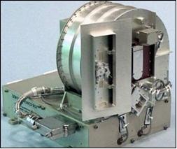
• GIM (Genesis Ion Monitor). The ion spectrometer is a spherical-section electrostatic analyzer which uses a Z-stack MCP (Microchannel Plate) detector, plus the spacecraft spin, to ensure capture of the solar wind beam over a wide range of solar wind conditions. The FOV is 26º starting along the spin axis by about 3º in azimuth. There are 40 energy steps per spectrum, chosen from an array of 180 available steps spanning 200 eV/q to 25 keV/q. During one spin of the spacecraft GIM sweeps out a circle on the sky that is ~24º in radius with the center of the circle being coincident with the average solar wind flow direction at 1 AU.
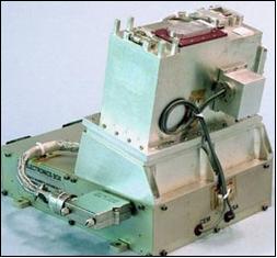
The electrostatic analyzer of GIM is negatively biased by a high-voltage power supply that steps across a number of voltage levels to build up an energy spectrum of the plasma population. GIM is basically an E/q analyzer but does have a mass analysis capability in this instance due to the similar flow velocities of all ions in the solar wind beam. The energy range of the instrument is ~100 eV to 14 keV, with a resolution of 5.2%, but only a small fraction of this range is used at any one time. Onboard software tracks the solar wind flow speed and autonomously adjusts the energy range that is scanned to keep it centered on the beam.
Both instruments, the GEM and GIM, were in continuous operation since shortly after launch in August 2001 until August 4, 2004, a month before sample re-entry.
Sample Canister Assembly
The collector arrays and the solar wind concentrator are mounted within the sample canister. The overall configuration of the instruments has been designed to achieve this ultra-clean environment within the canister by the exclusion of practically all sources of outgassing. While the solar wind collectors reside within the canister, the mechanisms and electronics mount on the outside of the canister. The only exception to this is the collector array deployment mechanism, which by necessity must be attached to the deployable arrays within the canister.
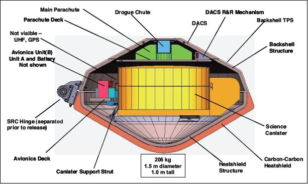
The canister structure consists of a base and cover, each machined out of a billet of aluminum alloy. The canister measures 78 cm in outside diameter and 38 cm in height. This structure supports the collectors, mechanisms and electronic boxes for the launch and recovery loads, and transfer them to the SRC through six interface struts.
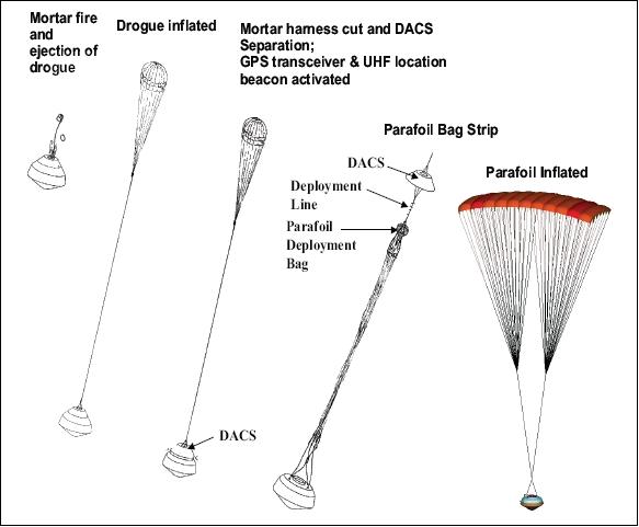
The canister and the avionics decks are mounted to the heatshield structure. The backshell contains the drogue parachute on the centerline and the parafoil main parachute is packed around the drogue canister. A mortar is fired inside the drogue canister to propel the drogue parachute out through the mortar cover. The DACS (Deployable Aft Conical Section) is released by firing three frangible pyrotechnic bolts (DACS Retention and Release Mechanism) and the drag load on the drogue parachute pulls the parafoil out, taking the DACS with it. Before releasing the DACS, the cable to the drogue mortar is cut with a pyrotechnic cable cutter.
Mission Status
- Aug. 8, 2001 - Launch of Genesis on a Delta-7326 vehicle from Cape Canaveral Air Station, FLA.
- Oct. 21, 2001 - Start of sample collection on the flight to L1.
- Nov. 16, 2001 - Halo orbit injection of the Genesis spacecraft.
- Dec. 3, 2001 - Start of sample collection at L1.
- Apr. 2, 2004 - Completion of sample collection mission. Solar wind collection was enacted during 884 days of the mission.
- May 2, 2004 - Earth ”flyby” of Genesis on the way to L2.
- Sept. 8, 2004 - The SRC (Sample Return Capsule) of the Genesis S/C returns into Earth's atmosphere. However, the mid-air capture by helicopter failed because the SRC parachute didn't open. As a result the SRC impacted into the desert of Utah causing some damage.
- Oct. 4, 2004 - The recovered science canister arrives at JSC (Johnson Space Center) in Houston.
- Oct. 14, 2004 - The mishap investigation board has identified a likely direct cause of the failure of Genesis' parachute system to open.
- Jan. 2005 - NASA scientists have sent to academic researchers an unprecedented piece of the sun gathered by the Genesis spacecraft, enabling the start of studies to achieve the mission's initial science objectives. The shipment to researchers at Washington University in St. Louis marked the first distribution of a Genesis scientific sample from JSC.
Return Mission
Reentry into Earth's atmosphere took place on September 8, 2004 over the Utah Test and Training Range (UTTR), where the S/C was tracked by the High Altitude Multiple Object Tracking System (HAMOTS). Two helicopters were vectored to the spacecraft location to catch the descending capsule on a parachute to avoid a hard ground-landing. ---- However, the parachute of SRC (Sample Return Capsule) didn't open due to a technical fault causing a hard landing in the Utah desert. Fortunately, the damage to SRC wasn't as severe as initially expected.

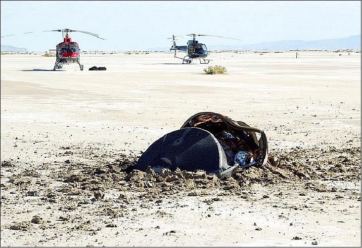
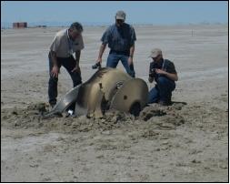
The JSC (Johnson Space Center) and JPL (Jet Propulsion Laboratory) workers presided over the return of the Genesis canisters containing solar wind samples to Houston. On Oct. 4, 2004, JSC's Astromaterials Curation Facility received the surviving fragments from the Genesis sample return capsule. The pieces were recovered from the impact site in the Utah desert, flown to Ellington Field in Houston, then shipped by van for the short ride to JSC.
NASA set up an Investigation Board to analyze the reentry mishap of the Genesis Sample Return Capsule. 10)
The Board determined the proximate (or direct) cause of the mishap to be that the G-switch sensors were in an inverted orientation, per an erroneous design, and were unable to sense sample return capsule deceleration during atmospheric entry and initiate parachute deployments. The Board found that deficiencies in the following four pre-launch processes resulted in the mishap:
• The design process inverted the G-switch sensor design
• The design review process did not detect the design error
• The verification process did not detect the design error
• The Red Team review process did not uncover the failure in the verification process.
Examination of the Recovered Capsule
Scientists at JSC (Johnson Space Center) have closely examined four Genesis spacecraft collectors, vital to the mission's top science objective, and found them in excellent shape, despite the spacecraft's hard landing. Surprisingly, the probe wasn't totally destroyed and much of the contents were protected on impact as the soft mud and sand of the desert lessened the blow. Fortunately, the solar concentrator of the probe helped to protect the samples. Also, the collector arrays allowed solar wind particles to be deeply embedded within the material, keeping them clear of any terrestrial material that may have contaminated the samples as the probe crashed. 11) 12)
Fortunately, the Genesis mission was lucky on impact - there are enough samples left uncontaminated by terrestrial debris and these tiny solar particles are beginning to help scientists understand the particles existing in the ultimate clean room: interplanetary space. Not only that, these particles hold the key to the development of our solar system (hence the ”Genesis” mission name) and provide clues to the development of stars, nebulae and planets in other systems.
• Genesis Findings Solve Apollo Lunar Soil Mystery: 13)
After comparing the sample return samples from the moon and those returned from the Genesis mission, the researchers conclude that the Apollo solar energetic particles do not exist. Both the Genesis and Apollo isotopic variations can be quantitatively explained by the fact that the Ne22 isotope is implanted deeper than the Ne20 isotope. Moreover, these findings indicate that there is no evidence for enhanced fluxes of high-energy solar particles billions of years ago compared to today.
• Genesis Scientists Finally Have Some Luck: Clues to Oxygen Content of Solar Wind: 14) 15)
Of particular interest will be the measurement of the primordial form of oxygen as it is emitted from the Sun in the solar wind. If the quantities of oxygen isotopes in the solar wind can be measured, then there will be a starting point from which other oxygen isotopes are formed from. The Earth, Moon and meteorites have vastly differing quantities of oxygen-16, oxygen-17 and oxygen-18. Why this is the case is a mystery to scientists. Using the Genesis data as a foundation to this work will help us understand how the oxygen isotopes evolved so differently in different parts of the solar system.
• Solar wind samples give insight into birth of solar system: 16) 17) 18) 19)
Most of the Genesis payload consisted of fragile solar-wind collectors, which had been exposed to the solar particles over a period of two years. Nearly all of these collectors were decimated during the crash. But the capsule also contained a special instrument built by a team at LANL (Los Alamos National Laboratory) to enhance the flow of solar wind onto a small target to make possible oxygen and nitrogen measurements. The targets of this Solar Wind Concentrator survived the crash and eventually yielded today’s solar secrets.
The analyzed data revealed differences between the sun and planets in oxygen and nitrogen, which are two of the most abundant elements in our solar system. Although the difference is slight, the implications could help determine how our solar system evolved. "We found that Earth, the moon, as well as Martian and other meteorites which are samples of asteroids, have a lower concentration of the 16O than does the sun," said Kevin McKeegan, a Genesis co-investigator from UCLA. "The implication is that we did not form out of the same solar nebula materials that created the sun -- just how and why remains to be discovered." 20)
The results provide new clues to how the solar system was formed. Oxygen and nitrogen samples collected from various meteorites, as well as nitrogen sampled in lunar soil and in the Jupiter atmosphere by the Galileo probe, vary significantly from that on Earth by cosmochemical standards: 38 percent for nitrogen and up to 7 percent for oxygen. With the first solar wind samples in hand, showing the early Sun’s composition, scientists can begin the game of determining where Earth’s different O and N came from.
"For nitrogen, Jupiter and the Sun look the same," said Roger Wiens of LANL and Genesis flight payload lead. "It tells us that the original gaseous component of the inner and outer solar system was homogeneous for nitrogen, at least. So where did Earth get its heavier nitrogen from? Maybe it came here in the material comets are made of. Perhaps it was bonded with organic materials."
For oxygen, the evidence points toward a different astrophysical mechanism called photochemical self-shielding, which the authors believe modified the composition of space dust before it coalesced to form the planets, including Earth. According to the article (Ref. 18), the Sun shows an enrichment of pure 16O (isotope of oxygen) relative to Earth instead of differences in 16O, 17O, and 18O that are proportional to their atomic weight or some other mixture that doesn’t show exclusive enrichment of a single isotope. This unique arrangement strongly favors the self-shielding theory, in which solar UV radiation was responsible for uniformly enhancing the two rarer isotopes, 17O and 18O, in the terrestrial planets.
References
1) P. Hong, G. Carlisle, N. Smith, “Look, Ma, No HANS!” Proceedings of the IEEE Aerospace Conference, Big Sky, MT, March 9-16,2002
2) “Genesis SolarWind Sample Return Mission,”NASA, URL: http://www.jpl.nasa.gov/news/fact_sheets/genesis.pdf
3) http://genesismission.jpl.nasa.gov/
4) D. Rapp, F. Naderi, M. Neugebauer, D. Sevilla, D. Sweetnam, D. C. Wiens, D. Burnett, et al., “The Suess-Urey Mission (Return of Solar Matter to Earth),” Acta Astronautica 39, 1996, pp. 229-238
5) A. J. Jurewicz, D. S. Burnett, R. C. Wiens, et al., ”Genesis Solar -Wind Sample Return Mission: The Materials,” Proceedings of the 31st Lunar and Planetary Science Conference, March 13-17, 2000, Houston, TX
6) D. J. McComas, B. L. Barraclough, R. W. Moses, R. C. Wiens, L. Adamic, D. Burnett, M. Neugebauer, “Solar Wind Concentrator,” Measurement Techniques in Space Plasmas: Particles, Geophysical Monograph 102, AGU, 1998
7) J. E. Nordholt, R. C. Wiens, R. A. Abeyta, J. R. Baldonado, D. S. Burnett, P. Casey, D. T. Everett, J. Kroesche, W. L. Lockhart, P. MacNeal, D. J. McComas, D. E. Mietz, R. W. Moses Jr., M. Neugebauer, J. Poths, D. B. Reisenfeld, S. A. Storms, C. Urdiales, “The Genesis Solar Wind Concentrator,” Space Science Reviews, Vol. 105, No 3-4, 2003, pp. 561-599
8) http://genesis.lanl.gov/instrument.html
9) http://genesis.lanl.gov/index.html
10) “Genesis Mishap Investigation Board Report,” Volume I, Oct. 2005, URL: http://www.nasa.gov/pdf/149414main_Genesis_MIB.pdf
11) “NASA Announces Key Genesis Science Collectors In Excellent Shape,” Release: 05-102, April 20, 2005, http://www.nasa.gov/home/hqnews/2005/apr/HQ_05102_genesis_collectors.html
12) Allen Witkowski, “Evaluation of Long Term Space Effects on Textiles from the Genesis Drogue Parachute,” Proceedings of the 2010 IEEE Aerospace Conference, Big Sky, MT, USA, March 6-13, 2010
13) “NASA Announces Key Genesis Science Collectors In Excellent Shape,” April 20, 2005, URL: http://www.nasa.gov/mission_pages/genesis/media/Genesis_findings.html
14) Universe Today, March 16, 2008, URL: http://www.universetoday.com/2008/03/16/genesis-scientists-finally-have-some-luck-clues-to-oxygen-content-of-solar-wind/#more-13181
15) P. Rincon, “Crashed probe yields Sun secrets,” BBC, March 15, 2008, URL: http://news.bbc.co.uk/2/hi/science/nature/7299025.stm
16) Genesis sub-index of Official NASA Web Site on past missions, URL: http://www.nasa.gov/mission_pages/genesis/main/index.html
17) “Genesis mission yields solar isotopic composition despite hard landing,” LANL, June 23, 2011, URL: http://www.lanl.gov/news/releases/solar_wind_samples_give_insight_into_birth_of_solar_system.html
18) K. D. McKeegan, A. P. A. Kallio, V. S. Heber, G. Jarzebinski, P. H. Mao, C. D. Coath, T. Kunihiro, R. C. Wiens, J. E. Nordholt, R. W. Moses Jr., D. B. Reisenfeld, A. J. G. Jurewicz, D. S. Burnett, “The Oxygen Isotopic Composition of the Sun Inferred from Captured Solar Wind,” Science, Vol. 332, No. 6037, (24 June 2011, pp. 1528-1532, DOI: 10.1126/science.1204636
19) B. Marty, M. Chaussidon, R. C. Wiens, A. J. G. Jurewicz, D. S. Burnett, “A 15N-Poor Isotopic Composition for the Solar System As Shown by Genesis Solar Wind Samples,” Science, Vol. 332, No 6037, June 24, 2011, pp. 1533-1536, DOI: 10.1126/science.1204656
20) “NASA Mission Suggests Sun and Planets Constructed Differently,” NASA, June 23, 2011, URL: http://www.nasa.gov/mission_pages/genesis/media/genesis20110623.html
The information compiled and edited in this article was provided by Herbert J. Kramer from his documentation of: "Observation of the Earth and Its Environment: Survey of Missions and Sensors" (Springer Verlag) as well as many other sources after the publication of the 4th edition in 2002. - Comments and corrections to this article are always welcome for further updates (eoportal@symbios.space).