Heinrich Hertz Mission
Non-EO
DLR
Communications
Quick facts
Overview
| Mission type | Non-EO |
| Agency | DLR |
Heinrich Hertz Satellite Mission (H2SAT)
Spacecraft Launch Payloads Ground Segment References
DLR (German Aerospace Center) is developing a geostationary communications satellite mission, called ‘Heinrich Hertz‘ after the German 19th-century physicist (1857-1894) who discovered the electromagnetic waves and expanded the electromagnetic theory of light that had been put forth by the Scottish physicist and mathematician James Clerk Maxwell (1831-1879). The objective of the mission is to explore and demonstrate new communication technologies in space at a technical and scientific level in order to determine how broadband communications, for example, can result in high data rates for mobile end users.
The satellite project, a technology demonstration mission, will permit German universities, research institutes, as well as industrial companies to conduct a multitude of experiments, thus giving scientists and engineers a head start in the development of new communication technologies and services. Beyond that, ‘Heinrich Hertz‘ will contribute to the further development of space technologies for the communications satellites of the next generation.
The project is funded by the German Federal Ministry of Economics and Technology (BMWi). The phase A of the project started in mid-2009. Planned for launch in 2016, the satellite will operate for 15 years and verify new payload technologies in orbit. 1)
OHB System AG of Bremen is the lead in the national Heinrich Hertz syndicate comprising Tesat-Spacecom GmbH, Audens Telecommunications Consulting, DLR/GSOC, SciSys Deutschland GmbH, HPS, INVENT, Astrium, Inradios GmbH, Dresden, and DLR/IKN (Institute of Communications and Navigation).
In accordance with the German space strategy the Heinrich-Hertz mission shall achieve the following goals: 2)
• Maintaining and developing key skills of German payload and platform technologies for geostationary communication satellites
• Securing and strengthening system capability for payloads of geostationary communications satellites
• Demonstration of scientific/technical communication experiments including new ground technologies
• Maintaining and expanding the system capability for small geostationary communication satellites in an independent German Mission
• Provision of satellite transponder capacity for the tasks of the German Ministry of Defense.
Newly developed technologies in space are a long way from future use. The results of IOV (In-Orbit Verification) form the basis for follow-on activities. Ten IOV units – manufactured by German universities, institutes and companies – implementing various new technologies, are foreseen to fly on the Heinrich-Hertz satellite as part of a scientific payload. A deliberate payload design allows grouping the IOV units together with conventional equipment in order to form fully functional communication transponders. A set of dedicated communication experiments has been designed in order to explore the capabilities of this payload and the IOV equipment.
The scientific payload does not require the full payload capacity of the SmallGEO (SGEO) platform which was developed in frame of the ESA Artes 11 Development Program. The remaining capacity is used by a hosted payload of the German Federal Ministry of Defense (BMVg). The hosted payload will cover the future communication needs of the German Armed Forces.
The Heinrich Hertz mission is the first joint undertaking by the two ministries in Germany, realized by the DLR Space administration as single customer to the industry. The system's design ensures that both payloads can operate independently from each other and that the special security needs of the military customer are met. This approach ensures the consistency of the dual purpose requirements.
The payload IOV units are included in the IOV communications payload. Besides the individual tests of the IOV units, the IOV payload allows to group the IOV units functionally to form a repeater, which enables functional tests on system level between the ground stations and the geostationary satellite. The IOV payload provides redundant paths for all IOV units. This robust design ensures the functionality of the overall repeater that will not be impeded by any combination of failures of the IOV units.
More than forty communications experiments have been defined that will utilize the IOV payload. The experiments can be grouped in two types:
• The first one serves as a test bed for IOV units like the on-board processors.
• The other type does not depend on a dedicated IOV unit but explores new applications for satellite communications as e.g. test bed for civil UAVs, Ka-band intersatellite links and mobile ground terminals. A subset of the communication experiments defines scenarios for flexible payload demonstrating the benefit of e.g. full-beam interconnectivity within a dynamic environment.
Spacecraft
The new SGEO (Small Geostationary Satellite Platform) of the ESA ARTES-11 (Advanced Research in Telecommunications Systems) program has been selected as the spacecraft bus for the Heinrich Hertz mission. The SGEO bus is being developed by a European consortium and led by OHB- System AG of Bremen, Germany. The commercial (i.e., SGEO follow-up) version of the SGEO bus is referred to as Luxor by OHB. 3)
Being part of the SGEO family, the intention for the Heinrich Hertz satellite has been to re-use as much as possible of the predecessor platforms from H36W-1 (a telecommunication satellite of Hispasat) and EDRS-C (European Data Relay Satellite-C) of ESA. Among the many smaller adaptations, three major drivers for the satellite design can be identified.
The first major challenge for the satellite design is the accommodation of the Heinrich Hertz telecommunication payloads. Table 1 shows a global comparison the payloads of the Heinrich Hertz mission and the predecessor SmallGeo H36W-1. One sees that while the power demand for H36W-1 was higher, the Heinrich Hertz payload is significantly heavier, has more antennas and has an increased demand for command and telemetry interfaces.
Parameter | H36W-1 | Heinrich Hertz |
Payload mass | 380 kg | 435 kg |
Payload power | 4.1 kW | 3.6 kW |
No. of repeater TMTC interfaces | 650 | 1150 |
No. of antennas | 2 steerable + 1 direct radiating array | 8 (all steerable) |
The second major challenge is the number of different operation scenarios that are required to test the individual IOV units and perform the variety of communication experiments.
A third challenge is the accommodation and operation of two different electric propulsion systems – the SPT-100 HET (Hall Effect Thruster) and the HEMPT (High Efficiency Multistage Plasma Thruster). The HEMPT Thruster Assembly comprises the Thruster itself, the PSCU (Power Supply Control Unit) and the FCU (Flow Control Unit).
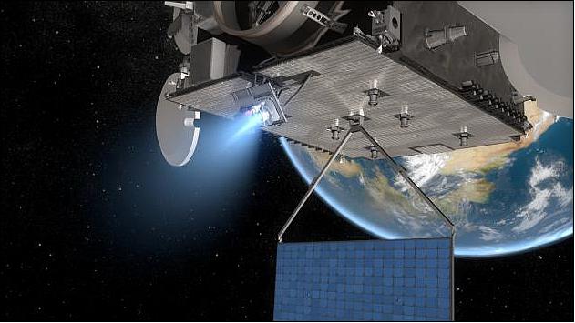
The major reason to introduce electrical propulsion is the mass gain: electric propulsion needs fewer fuel compared to chemical propulsion that allows to launch nearly 2 times more payload without changing the overall satellite mass. Other advantages: reduced launch cost, potentially longer mission lifetime. For Heinrich Hertz, the requirement is to utilize the new HEMPT system as the primary system and keep the HET system with its long in-orbit heritage as the back-up solution. The higher specific impulse of the HEMPT system can lead to an even more reduced xenon consumption of 91 kg compared to 145 kg when using the HET system (depending on the operational scenario's). Theoretically by using the HEMPT system instead of HET the overall xenon payload could be reduced from 145 kg to 91kg.
That would mark a significant mass reduction. But for the Heinrich Hertz mission, the worst case has to be taken into account. That means the satellite must be able to stay in orbit in case the HEMPT system has a malfunction in the some phase of the mission. In this case the positioning can only be made by the HET propulsion. For this reason 145 kg xenon are needed as fuel.
Each of the electronic propulsion systems has its own set of thrusters, which provide different thrust levels and specific impulses and are connected to different supply units. Usually redundancy is implemented by using several instances of identical units; in this case the back-up system is significantly different to the nominal system (Table 2). HEMPT and HET are used on Heinrich Hertz for north and south positioning.
Parameter | HET | HEMPT |
No of thrusters | 2 | 2 |
Power consumption | 1.6 kW | 1.6 kW |
Thrust | 75 Nm | 43Nm |
Specific impulse | 1440 s | 2300 s |
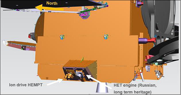
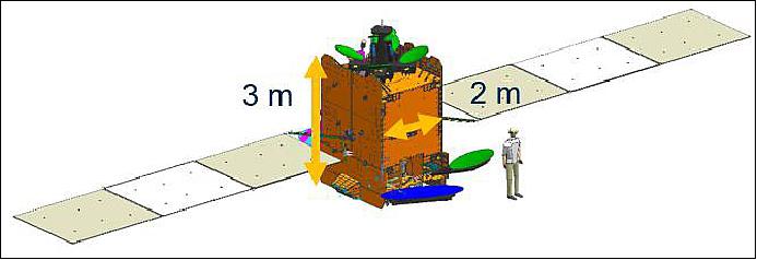
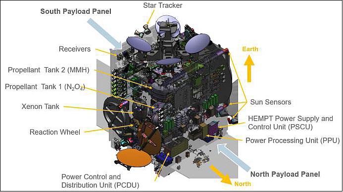
The design of the Heinrich Hertz satellite is a combination of re-used from predecessor missions, product line evolution and mission specific modifications. It's interior is shown in Figure 4.
Lifetime | 15 years operational |
Launch mass | 3450 kg |
Platform reliability | Better than 0.86 @ EOL (End of Life) |
Payload capacity | 435 kg and 3.6 kW |
Pointing accuracy | Better than 0.1º |
TM data rate | 8.192 kbit/s |
TC data rate | 1 ksample/s (S-band) and 4 ksample/s (Ku-band) |
Communication | Secure with encryption and authentication |
TCS (Thermal Control Subsystem): The TCS in the payload module IOV payload is faced with the challenges:
• to accommodate many different kinds of units with different footprints and different dissipation
• to accommodate a high variety of payload operation scenarios - all with varying dissipation in different parts of the payload.
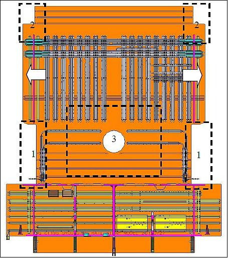
To meet these challenges a complex network of surface mounted heat pipes has been designed. Embedded heat pipes would have prevented the needed flexibility for accommodating the IOV units under development. In combination with heaters and potentially local MLI (Multi-Layered Insulation) patches on the radiator the design ensures the maintenance of equipment temperatures within the specified limits.
The modification to the payload radiators has increased the accommodation surface by roughly 0.7 m2. The change of material for the Earth deck has increased the allowed base contact heat flux from 0.01 W/cm2 to 0.05 W/cm2 (aluminum honeycomb panel), respectively, 0.1 W/cm2 (aluminum with doubler).
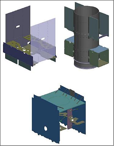
Structural Modular Concept: (Reuse from: H36W-1, EDRS-C). The structural modular concept is based on central cylinder serving as the backbone of the spacecraft and accommodating the two bi-propellant tanks inside. The major spacecraft modules are the:
• Propulsion Module
• Core Platform Module
• Repeater Module
The modular concept allows the different modules to be integrated, accommodated and tested separately before being integrated to the complete spacecraft. For the Heinrich Hertz mission the modules are subject to parallel integration and testing at the premises of the propulsion supplier, payload supplier and OHB at the same time.
In summary, Heinrich Hertz - the next member of OHBs SGEO family - is on its half way to the mission start. The satellite design is facing the system CDR (Critical Design Review). The integration of the satellite started and is proceeding. It is targeted to be operational in 2022.
Heinrich Hertz has a variety of experimental communication units for in orbit verification on board which will pave the way for future, affordable telecommunication applications. It marks a new step in Germany's ability to use space as a communication platform and provides a number of services for science and military use. During its 15 years lifespan it is able to adapt onto changing communication standards and requirements.
The geostationary satellite system consists of the space segment, the launch segment, the ground segment and GSE. The ground segment contains the satellite control, separate mission and payload controls for both the scientific and military mission, and ground stations for operation of the satcom networks for both missions. The Design of the system makes best use of existing designs, infrastructures and processes (SGEO platform development, existing military and civil ground elements).
Mission architecture: The CTRS (Customer Technical Requirement Specification) imposes a high level baseline architecture, which is the reference for any development throughout the design phase. It is a primary requirement that both mission parts operate independently from each other to the maximum possible extent. This is reflected in each part of the mission design.
The primary mission requirement calls for both mission parts to operate independently from each other to the maximum possible extent. This is reflected in each part of the mission design.
Mission Status
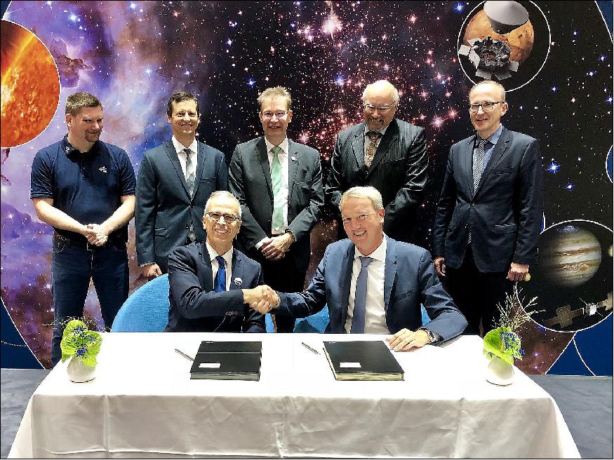
• October 2, 2018: OHB System AG, a subsidiary of listed technology group OHB SE, has awarded the principal subcontract for the national Heinrich Hertz satellite mission today at the International Astronautical Congress (IAC 2018) in Bremen in the presence of representatives of the Space Administration of the German Aerospace Center (DLR): The Backnang-based company Tesat has received a contract from OHB for the assembly and verification of the scientific/technical payload and for the construction of the repeater for the military payload on board the communications satellite. 4)
One Mission, Two Goals
Heinrich Hertz comprises a number of different missions: For one thing, DLR will be gaining a powerful platform for conducting various experiments in the field of satellite communications and, for another, the German Federal Ministry of Defense will have its own military segment of the payload providing satellite transmission capacities for the German federal armed forces on a long-term and future-proof basis.
1) The main aspect of the civil segment of the mission entails in-orbit verification of new technologies. For this purpose, roughly one dozen new technologies for satellite communications developed by industrial companies and research institutions will be tested on board the satellite. In addition, a series of scientific/technical communications experiments will be carried out. The satellite platform developed by OHB will be able to meet the resultant requirements to optimum effect.
2) With the additional separate military payload capacity on board the satellite, the German federal armed forces will be able to make a contribution to covering the steadily growing requirements which the armed forces have for satellite-based communications to manage and support their operations. An agreement has been entered into between the Federal Ministry for Economic Affairs and Energy and the Federal Ministry of Defense assigning DLR Space Management responsibility for coordinating these mission components.
All in all, the national Heinrich Hertz satellite mission will be furthering the continued development of space technology for communications satellites in a partnership comprising research institutions, universities and the German space industry.
• September 21, 2018: The Mainz-based company MT Mechatronics Germany, a subsidiary of MT Aerospace AG within the OHB group, has today been awarded a contract for the production and delivery of five antennas by prime contractor SCISYS Deutschland GmbH for the ground segment of the "Heinrich Hertz" national satellite communications mission. 5)
- The five ground stations with antenna diameters between 7.3 to 13 meters will be performing various functions within the ground segment (in Germany). They will make it possible to control the satellite, execute and monitor the experiments and utilize the communication payloads on board of the satellite.
- With the German "Heinrich Hertz" satellite communications mission, it will be possible to test new technologies under the extreme conditions of outer space and to carry out around 20 communications, antenna and satellite technology experiments on board the satellite. In addition, the satellite will be fitted with an independent telecommunications payload, which will be used by the Federal Ministry of Defense for communication purposes. Heinrich Hertz is being sponsored by DLR Space Management using funds provided by the Federal Ministry of Economics and Energy (BMWi) and with the participation of the Federal Ministry of Defense (BMVg).
• On 14 Dec. 2017, OHB System AG, a subsidiary of the Bremen-based space technology group OHB SE, has today signed a contract with the European launch services provider Arianespace for the launch of the Heinrich Hertz civil/military telecommunications satellite. In doing so, OHB has secured a flight opportunity on board an Ariane-5 launch vehicle. The Heinrich Hertz satellite will be launched into GEO in Q4 2021. With a mass of 3.5 tons, the satellite will lift off from the European Kourou space center in French-Guyana. 6) 7) 8)
• On June 28, 2017, Gerd Gruppe, DLR Executive Board Member for the DLR Space Administration, and Marco Fuchs, Chief Executive Officer of OHB System AG, signed a contract to manufacture, test and launch the German 'Heinrich Hertz' communications satellite. 9)
- In a contract awarded by the German Federal Ministry of Economics and Technology, the German Aerospace Center is examining the feasibility of a national satellite communications mission based on the preliminary studies (Phase 0) conducted by an industrial team lead-managed by OHB-System. This will form the basis for a national project (Heinrich Hertz communications satellite (H2Sat)).
- The Heinrich Hertz mission aims to explore and test new communications technologies in space at a technical and scientific level in order to determine how broadband communications, for example, can result in high data rates for mobile final users.
- The mission will offer universities, research institutes and industry a platform for conducting numerous scientific/technical experiments. The selection of the new German satellite SGEO will simultaneously support the goal systematically being pursued by ESA and Germany in the ARTES 11 program of building up system skills in this area in Europe and extending German capabilities in the area of satellites and telecommunications payloads.
• August 23, 2016: OHB System AG has been awarded a contract by DLR Space Administration to oversee numerous new communications technologies. These technologies, designed by different industry companies and institutes, will be integrated in the Heinrich Hertz satellite so that they can be tested in space. 10)
- Under the national Heinrich Hertz satellite mission, DLR Space Administration is working on behalf of the German Federal Ministry for Economic Affairs and Energy to perform scientific tests on the new communications technologies in orbit over an extended period of time. The purpose is to "test the behavior of these new technologies under extreme conditions in space," explains Dominik Lang, Director of Telecommunications Satellites and Head of the Heinrich Hertz satellite project at OHB.
- This in-orbit verification process will be demonstrating the suitability of the technologies for future satellite missions, thus substantially reducing the risk of failure. In addition, the Heinrich Hertz mission will be offering numerous research institutions as well as industry a platform for conducting a multitude of scientific/technical experiments.
- Under the technology management contract for the Heinrich Hertz satellite mission, OHB is responsible for the scientific/technical aspects of the technology orders. This entails responsibility for the technical and formal project milestones as well as formal acceptance testing of the hardware for integration in the Heinrich Hertz satellite. One of OHB's primary tasks is to ensure that the interfaces of the technologies to be tested are compatible with the Heinrich Hertz satellite.
Launch
A launch of the Heinrich-Hertz spacecraft is planned for 2023. In 2017, OHB signed a contract with Arianespace for the launch of the H2SAT mission on Ariane-5ECA from Kourou. 11)
Orbit: GEO (Geostationary Earth Orbit), altitude = 35,786 km, longitude = 17.6 E.
Sensor Complement
In the space business, there is typically a quite long period from the design and development of new technologies to their commercial use. Even comprehensive tests on ground cannot replace long-lasting experiments and tests in space. Such IOV (In Orbit Verification) activities provide the scientific basis for the introduction and application of new technologies and the necessary heritage for commercial satellite programs. The GEO Heinrich-Hertz communications mission establishes a valuable basis to verify new technologies scientifically in orbit over a long period of time and to gain heritage regarding their performance in space. In addition, research institutes and the industry are enabled to perform numerous scientific and technological experiments over the full life time of 15 years. 12)
Payload accommodation: The spacecraft supports a payload with a mass of up to 430 kg and a DC power of up to 3.6 kW (EOL). Payload mass and power are shared between the scientific payload and the hosted military payload. In terms of electrical interfaces to/from the payload, two PMUs (Payload Management Units) are accommodated (one on each radiator panel) to manage the payload TM/TC and also to provide fuses for all required payload power outlets. A PLIU (Payload Interface Unit) is implemented as TM/TC interface between the PMU and the payload. In addition to dedicated TM/TC lines, a MIL-STD-1553B bus is used. A CAN (Controller Area Network) bus is implemented between the PLIU and certain payload units (Ref. 2).
The scientific payload is accommodated on the north radiator panel whereas the hosted military payload is accommodated on the south panel. This facilitates the required separation between both payloads. The scientific payload is specially demanding in terms of accommodation and detailed power consumption and dissipation budgets have been computed. Due to its experimental nature, high demanding power experiments could be run during phases with adequate solar illumination conditions, while other experiments could be grouped to be run simultaneously, although the baseline approach is to run most of the experiments sequentially. Thus, power consumption and dissipation are at the limit of the performance range of the platform.
Eight reflector antennas are accommodated on the satellite as depicted in Figure 9. The steerable South beam antenna (Ka-band) and the fixed H2KAR (Ka-band Reflector) antenna are mounted on the West side of the satellite. The anchor beam antenna (Ku-band) is mounted on the East side of the satellite together with an antenna of the military payload in a dual-deployment arrangement. The Earth deck hosts the ISL (Inter-Satellite Link) tracking antenna (ISL Ka-band) and three other antennas of the military payload. These four reflector antennas are mounted onto a central ATM (Antenna Tower Module). The GeReLEO Smart antenna (ISL Ka-band) is mounted on the Northern extension panel. One of the S-band TT&R hemispherical antennas is mounted on top of the ATM, while the other is on the anti-Earth deck side. Additionally, the beacon horn antennas feed assemblies for the side-deployable reflectors and a star tracker are accommodated on the Earth Deck.
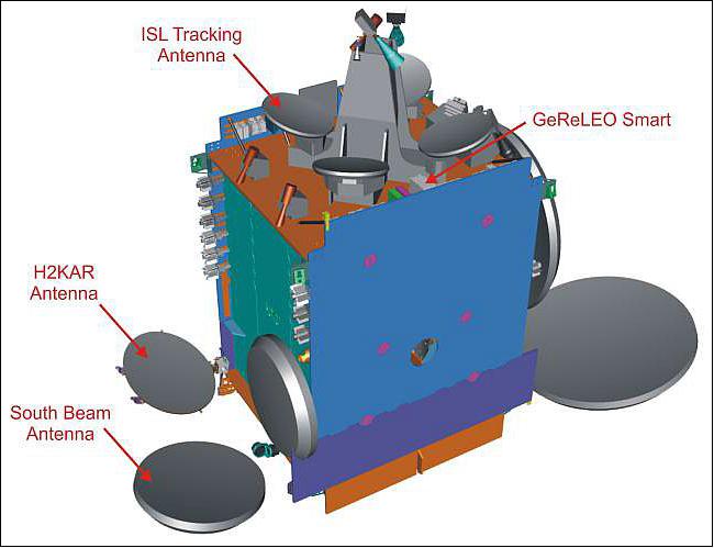
A number of new and innovative technologies for payload and platform are selected as flight equipment on the Heinrich-Hertz satellite by DLR-RfM (German Aerospace Center – Space Administration). These technologies are incorporated into self-standing IOV units and integrated onto the satellite. With the successful test of the IOV unit the associated technology gains flight-heritage which is an essential asset for follow-on developments. Table 4 provides a short description of the 10 selected IOV units. Nine of these 10 units targets future use in telecommunication payloads. The last one – the HEMPT Thruster Assembly – is a high efficiency electric propulsion thruster developed in Germany driven by Xenon and used for satellite position maintenance.
IOV (In-Orbit Verification) Payload
The scientific mission aims at developing system capability for communications payloads on small geostationary satellites and testing new technologies and techniques at payload, platform and ground level. Selected technologies are implemented within dedicated IOV units which are part of the platform or the scientific Ka/Ku-band payload (Ref. 3).
IOV unit | Unit responsibility | Description |
Next OBP | DLR. IQ Wireless | In-orbit reprogrammable on-board processor, 1.5 GHz, one channel. |
FhG OBP | Fraunhofer IIS | In-orbit reprogrammable on-board processor with multiple FPGAs, |
GeReLEO Smart (GEO | Steinbeis TZR | Multibeam ISL Ka-band receive antenna, intended for intersatellite link, |
H2KAR (H2 Ka-band | HPS (High Performance | CFRP reflector antenna,20/30GHz,for low mass, high stiffness and low |
Flex INET 13) | Tesat Spacecom | In-orbit tunable input filter with four Ka-band channels. |
Flex OMUX | Tesat Spacecom | In-orbit tunable output filter (OMUX) with three Ka-band channels. |
300 W FPM 14) | Tesat Spacecom | Flexible and Programmable Ku-band Power Module with up to 300W |
250 W FPM | Tesat Spacecom | Flexible and Programmable Ka-band Power Module with up to 250W |
PLIU (Payload Interface | Tesat Spacecom | PLIU providing communications between the platform MIL-STD-1553 |
HEMPT | Thales Deutschland | HEMPT (High-Efficiency Multistage Plasma Thruster) |
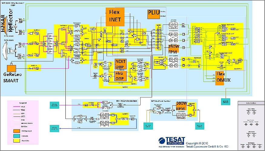
The payload IOV units are included in the IOV communications payload. Besides the individual tests of the IOV units, the IOV payload allows to group the IOV units functionally to form a repeater, which enables functional tests on system level between the ground stations and the geostationary satellite. The IOV payload provides redundant paths for all IOV units, as shown in Figure 10. This robust design ensures the functionality of the overall repeater, that will not be impeded by any combination of failures of the IOV units.
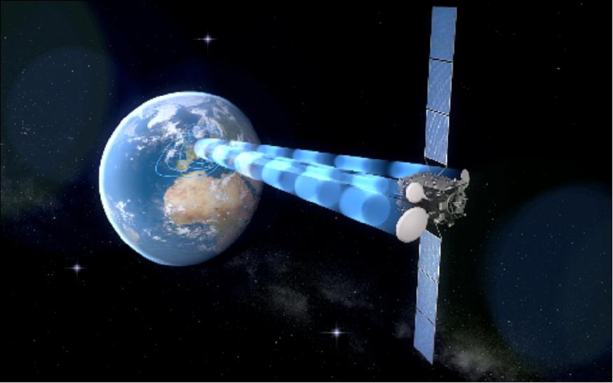
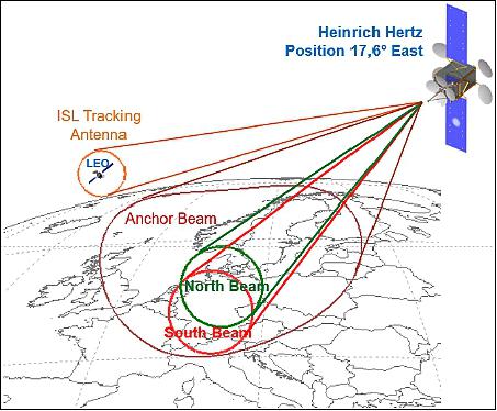
Payload Design – future technology for new communication applications: Especially the Heinrich Hertz IOV payload offers a number of unique applications, which will be experimental demonstrated and verified in-orbit. Heinrich Hertz is able to perform on-board digital signal regeneration. This provides for the end users improved link quality. For example this feature allows to connect small (nomadic) terminals which is a key piece for implementing the Internet of Things. To fulfil the changing needs for different coverage zones Heinrich Hertz is equipped with two steerable spot beams. Therefor the satellite can stay flexibility and can easier adapt to changing mission requirements. The concept of north and south beam can be seen in Figure 11.
The goal is to increase the availability of mobile phone and internet connection in remote areas like mountains, off-shore wind parks and oil platforms. Also in critical situations in and after catastrophic events the police, fire department and other authorities can use the Heinrich Hertz satellite as back-up to supplement terrestrial (remaining) communication networks.
The new IOV Payload technology allows to have a dynamic allocation of transmission capacity (bandwidth and data rate). Those "individualized" channels can also be used for individual video streaming.
Heinrich Hertz technology enables also flexible in-orbit digital IP routing. This gives the possibility for direct single-hop interconnection which leads to shorter delays in the communications process. It can work as digital telephone exchange or data cross point for thousands of users.
In interaction, the IOV payload units give Heinrich Hertz a unique skillset. But regarded separately, the units have also some remarkable features like the flexible Ka/Ku amplifiers. These are capable of a flexible power transmission which leads to a more efficient use of the satellite power resources.
The GeReLEO (GEO data Relay for LEO ) patch antenna provides multiple intersatellite links with electronic beam steering. For example this can be used as data relay between LEO (Low Earth Orbit) satellites and the ground station. Normally LEO satellites just have a small time window in which they can exchange data with their ground stations. With Heinrich Hertz, the link between the LEO satellite and the ground station time window expires. The LEO satellite can send data to ground via Heinrich Hertz as relay. This increases the amount of data a LEO satellite can transmit to earth and thereby it's effectiveness.
The Heinrich Hertz Mission is planned for 15 years, similar to the commercial communication missions. In the last 15 years the transmission standards and features for mobile communication were under constant change. This trend will most likely continue for the period of the mission. To ensure that satellites can align during their operation to those changes, an in-orbit reconfigurable digital processor invented by the Fraunhofer institute (FOBP) is part of the payload. Heinrich Hertz also has a second on-board processor called Next-OBP.
The improvements of technologies are now allowing to implement highly efficient OBPs able to process hundreds of Gbits within a small SWAP (Size, Weight and Power).
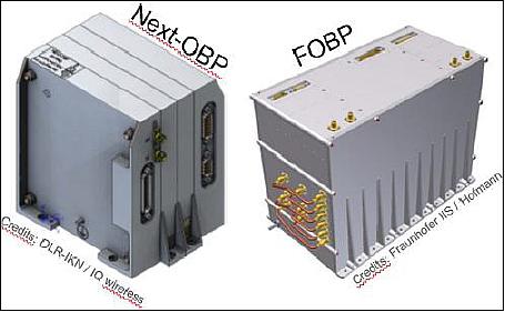
The FOBP is a powerful and flexible programmable communication payload for satellite-based, digital signal processing applications. The FOBP consists of radiation-hardened, latest-generation field programmable gate arrays (FPGAs) suitable for space applications. These FPGAs make it possible to fully reconfigure the FOBP from the earth station. That means the processor can be adapted to new communication standards and to changing environmental conditions while in orbit any time. To date, communication satellites operate almost exclusively with transparent transponders that receive the signals from the earth station, amplify them and transmit them back. The FOBP can process the received signals in addition, before returning them to ground stations or forwarding them on to other satellites (regenerative payload). 15)
Fraunhofer IIS is responsible for the following parts of the mission:
• Development of new protocols, e. g. for direct satellite communication
• Testing of new modulation and coding schemes
• In-orbit verification of radiation sensors (together with Fraunhofer INT):
- Absorbed radiation dose (UV EPROM)
- Solar particle events (SRAM, BRAM in FPGA)
• Research into adaptive single event upset (SEU) mitigation methods for configuring the optimal redundancy in an FPGA
• In-orbit verification of the HallinOne® technology for contactless measurement of the FPGA power consumption.
High Flexibility for Future Communications Standards
The use of FPGAs means the processor's hardware architecture can be reconfigured, offering maximum flexibility for a range of applications. This provides a basis for the implementation of transmission techniques to be developed. The entire digital signal processing chain can be reconfigured by uploading configuration files. Thanks to a transponder bandwidth of up to 450 MHz, the FOBP is highly versatile and suited to new communications standards:
• Hardware architecture based on two state-of-the-art FPGAs that can be reconfigured from the earth station to guarantee maximum flexibility for a wide variety of applications.
• Radiation-hard, high-speed ADCs and DACs that enable direct sampling of the L-band intermediate frequency.
• Availability of higher bandwidth enables high data rates for broadband communication with stationary terminals and mobile devices.
In addition, the OBP enables user-to-satellite communication (return link). Research is being done into a variety of techniques for receiving, processing and retransmitting signals using an OBP. Fast parallel signal processing on board of the satellite guarantees the optimum signal-to-noise ratio. It also enables error correction, which brings benefits in terms of transmission power and bit rate.
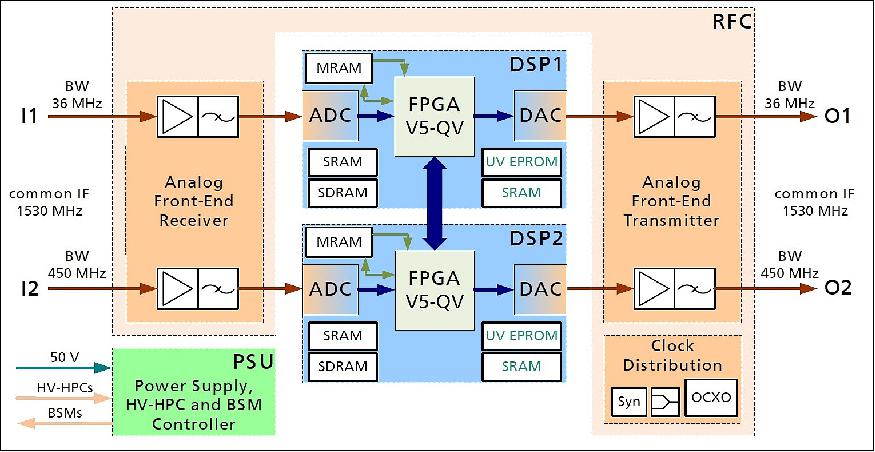
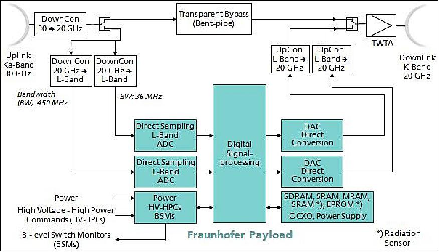
The FOBP (Fraunhofer On-Board Processor) will be used on the geostationary satellite "Heinrich Hertz" designed to operate for 15 years. The FOBP can be used for the following purposes:
- Satellite communications with return link capability for nomadic and mobile users
- Payload reconfiguration
- Measurement of solar radiation and TID (Total Ionizing Dose)
- Dynamic adaptation of the FPGA firmware to the current solar radiation condition
- Single-hop connectivity over IP (Internet Protocol)
- Flexible adaptation to existing systems due to its scalable bandwidth, which ranges from broadband to narrowband, such as for sensor data (power meters).
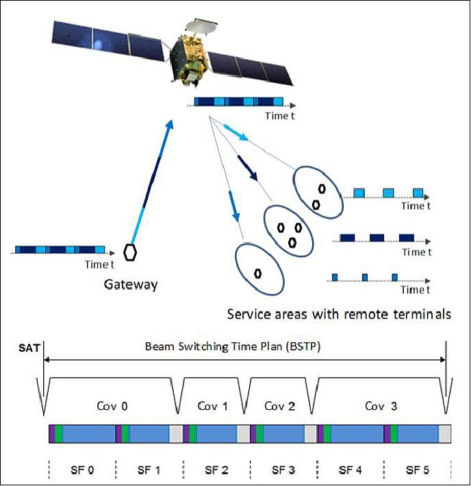
With the ability of on-board digital signal processing comes more than the above mentioned advantages. The signal regeneration and therefor the overall link-budget are significantly improved. For example this is an advantages for all small (and even nomadic) terminals and IoT applications. The signal quality can be kept high by interference and jamming mitigation. With this equipment the Heinrich Hertz technology is able to perform a new amount of traffic channelization. For this reason a method called beam-hopping is used. Essentially Heinrich Hertz distribute it's power through several beams. Every beam covers a certain area. For the most efficient use of amplifier power the satellite allocate it's power to beams which cover areas where high downlink rates are required. For example on a regular working day people travel from the suburban areas to the city core for work. Then in this area is a higher downlink rate needed. The principle of beam hopping can be seen in Figure 15. All these new IOV payloads technologies have a mass of ~ 200 kg and offer beside the above discussed operational features an overall data rate of about 1Gbit/s depending on coding and power density:
• 7 channels with 36 MHz bandwidth each at Ka-band (= appr. 7 x 50 Mbit/s = 350 Mbit/s)
• 1 channel with up to 450 MHz bandwidth at Ka-band (= appr. 1 x 625 Mbit/s)
• [1 ISL (Intersatellite Link) with 36 MHz bandwidth at Ka-band (= appr. 1 x 50 Mbit/s)]
• 1 channel with 45 MHz bandwidth at Ku-band (= appr. 1 x 62 Mbit/s)
Under good circumstances, even a higher data rate would be possible. Depending on a number of factors like transmission standard (DVBS2), modulation (QPSK) and signal-to-noise ratio, this would enable several hundreds of TV channels including new applications like video on demand even at HD (High Definition) quality and dedicated communication lines for small areas (or critical areas). — In this sense Heinrich Hertz will pave the way for future, affordable telecommunication applications.
More than forty communications experiments have been defined that will utilize the IOV payload. The experiments can be grouped in two types:
• The first one serves as a test bed for IOV units like the on-board processors
• The other type does not depend on a dedicated IOV unit but explores new applications for satellite communications as e.g. test bed for civil UAVs, Ka-band intersatellite links and mobile ground terminals. A subset of the communication experiments defines scenarios for flexible payload demonstrating the benefit of e.g. full-beam interconnectivity within a dynamic environment.
Additionally to the IOV payload, a communication payload of the German Ministry of Defense is embarked on the satellite. The satellite design enables the independent and parallel operation of the two payloads.
HSB (Hybrid Sensor Bus)
The HSB system is developed in the frame of an ESA-ARTES program and will be verified as flight demonstrator onboard the German Heinrich Hertz satellite in 2016. The HSB system is based on a modular concept which includes sensor interrogation modules based on I2C electrical and FBG (Fiber Bragg Grating) fiber-optical sensor elements. Onboard fiber-optic sensing allows the implementation of novel control and monitoring methods. For read-out of multiple FBG sensors, a design based on a tunable laser diode as well as a design based on a spectrometer is considered. 16)
Scientific (civilian) payload: The scientific payload can operate within the following coverage zones:
• Ka-band (20/30 GHz): one steerable spotbeam over South Germany and the H2KAR antenna (IOV) over North Germany (Figure 16).
• ISL (23/26 GHz): one ISL tracking antenna, steerable over the whole Earth and the receive GeReLEO Smart antenna (IOV).
• Ku-band (11/14 GHz): anchor coverage over Germany, also used by the military payload.
A deliberate payload design allows grouping the IOV units together with conventional equipment in order to form fully functional communication transponders. Thus, the scientific payload as a whole provides high flexibility in terms of frequency plan, interconnectivity, power and regenerative transmissions.
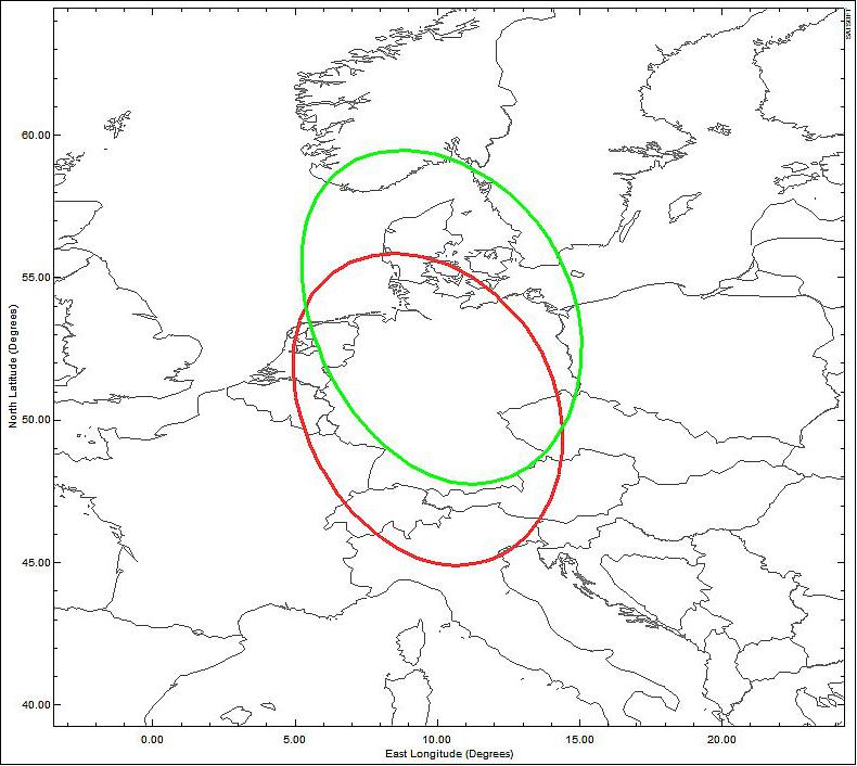
Three main sections can be differentiated in the scientific payload:
1) Ka-band section inclusive OBP (On-Board Processor).
The section is composed of the 30 GHz receive stage, the filter/OBP stage and the 20 GHz transmit stage. The 30 GHz stage receives the input signals from both Ka-band spotbeam antennas. The signals can be downconverted to 20 GHz and routed to the filter stage or cross-strapped to the ISL section. The filter/OBP stage performs the routing and channel-filtering to either the transmit stage or to the regenerative channels including the OBPs. Flexible filtering can be done by use of the Flex INET (IOV) or by conventional IMUXs. The 20 GHz transmit stage includes the 250 W FPM (IOV), the Dual Flex MPM (IOV), several conventional 130 W MPMs and a power-combining stage for two 130 W MPMs. After high-power amplification the signals can be combined by the tunable Flex OMUX (IOV) or by conventional OMUXs, prior to be routed to the antennas TX ports.
2) ISL (Inter-Satellite Link) section.
This section comprises the ISL tracking antenna, the GeReLEO Smart antenna (IOV) and a small repeater. The signals from either antenna are received by the ISL section and cross-strapped to the transmission stage of the Ka-band section. Alternatively, the ISL section routes the signals cross-strapped from the Ka-band 30 GHz receive section to the transmit port of the ISL tracking antenna.
3) Ku-band section (shared payload).
In order to optimize the resources of the Heinrich-Hertz mission, a shared payload part has been implemented additionally. The shared payload is used by both the scientific and military missions. The Ku-band antenna and low-noise amplifiers are shared with the military payload. Thus, the Ku-band section of the scientific payload is small and is mainly composed of the 300 W FPM (IOV) and a redundant 160 W MPM.
Specific communication experiments have been defined not only as a testbed for individual validation of the IOV units, but also for end-to-end system level testing of novel Satcom architectures and applications. The feasibility of the communication experiments has been confirmed by system simulations and link budget calculations. The communication experiments can be grouped as follows:
Regenerative Transponder Experiments
- Network coding experiments. This is a set of experiments explores network coding techniques making use of the Next OBP. The basic experiment is complemented by a multi-user detection experiment and an experiment on reliable multicast.
- Mobile/nomadic regenerative communications. This comprises multipoint-to-multipoint links through regenerative transponders (FhG OBP) involving mobile and nomadic terminals. The scenarios explore new communication protocols for single-hop transmission, novel modulation/coding techniques and their suitability for on-board processing, return channel capabilities, on-board IP switching, and on-board filtering.
Transparent Transponder Experiments
- ISL experiments. The main experiment implements a bidirectional TM/TC data relay to a LEO satellite by means of the ISL tracking antenna. Another experiment tests the GeReLEO Smart antenna.
- Communication to civil UAS (Unmanned Aircraft System). Bidirectional communication links for civil UASs in both Ku-/Ka-bands.
- Mobile/nomadic transparent communications. By means of conventional on-board switching, these experiments implement bidirectional links between mobile terminals located in both Ka-band spotbeams.
- Broadband applications experiment. It aims at assessing the performance of broadband applications by using a 450 MHz broadband channel in combination with high-order modulation schemes.
Military Payload
The purpose of the military payload of the H2SAT mission is the provision of military Satcom services over the whole visible Earth. The shared payload provides the homeland beam coverage over Germany (Ref. 2).
Ground Segment
The Heinrich Hertz ground segment consists of three major parts: the Satellite Control Segment, the IOV User Segment and the Military User Segment (Ref. 2).
1) Satellite Control Segment:
The Satellite Control segment is composed by TT&R, LEOP and IOT ground stations and the SCC (Satellite Control Center). The TT&R ground stations provide the link to the satellite for commanding and telemetry of the satellite platform and payloads. Two dedicated Ku-band TT&R stations are foreseen. Both have identical functions, which include the reception of TM from the spacecraft and routing it to the SCC, reception of TCs (Telecommands) from the SCC and transmission to the spacecraft, performing ranging measurements with the spacecraft and deliver the results to the SCC, and determine the pointing angle to the spacecraft and deliver it to the SCC. In the baseline concept, the main station is located in the DLR premises in Weilheim and the backup station is located in the DLR premises in Neustrelitz. The backup antenna is used for TM/TC if the prime antenna fails or is in maintenance.
Additionally, a global-wide S-band LEOP stations network will be used to provide almost continuous coverage for TM & TC communication and ranging. This serves to perform LEOP standard operations including critical activities that need to be executed in the early operational phase, GTO transfer and major part of platform IOT (e.g. solar array deployment, apogee maneuvers for GTO transfer, etc.).
To perform IOTs for the payload, adequate IOT ground stations are required to perform the measurements in Ku- and Ka-band. Either one ground station will be equipped to be capable of performing Ku- and Ka-band IOT measurements or two separate ground stations for each frequency band will be available. For the execution of each IOT adequate IOT test benches need to be installed, tested, and calibrated before application.
The SCC plans and executes the operation of the satellite and the payloads. The satellite control center consists of the subsystems Ground Data System, Flight Operations, Flight Dynamics and Mission Planning. These four systems together fulfill the tasks of satellite control. The external entities that have an interface with satellite control are the spacecraft (via TT&R Ground Stations) and both scientific and military POCs (Payload Control Centers). Among other functions, the SCC receives activity requests from the MCC (Mission Control Centers), commands the spacecraft, processes and delivers telemetry to the MCCs, and performs satellite and payload maintenance, contingency and emergency operations.
2) IOV User Segment:
The IOV user segment consists of the scientific Mission Control and its associated Payload Control, and the necessary ground stations. The MCC provides the functions for planning and execution of the communication links (e.g. communication experiments) and an interface to the users (e.g. experimenters) for their requests and required support by the User Segment. The commanding of the payload and the reception of the telemetry is performed via the Payload Control.
All system parameters of the space and ground segment are collected, consolidated and routed by the Mission Control. On-board parameters of the satellite payload and platform (telemetry data) which are relevant for the users (e.g. experimenters) are received through the associated Payload Control and monitored by the Mission Control. Ground-based parameters (e.g. from the Anchor Stations, Ground Stations, Terminals, etc.) are streamed to the Mission Control via direct links. Based on the mission planning, the Mission Control configures the Ground Segment and generates Activity Requests which contain the necessary information for commanding the payload.
Besides the Mission and Payload Control Centers, the User Segment contains the Anchor Stations in Ka- and Ku-band, which provide the RF communication link and serve as interface for the satellite payload data. Remote supervision and control functions of the Anchor Stations are provided by the MCC. Regarding the ground segment for the scientific mission, specific hardware will be installed to support some of the communication experiments (e.g. modems for special waveforms), which can be remotely monitored.
Most of the experiments of the H2SAT scientific mission rely on the measurement and evaluation of data signals through dedicated ground equipment. Access to such equipment is enabled through CSM (Communication Satellite Monitoring). The CSM infrastructure is composed of sensors integrated in fixed or transportable ground stations, which will be monitored and operated from the MCC in the anchor coverage and alternatively by workplaces implemented in transportable ground stations (TCSM) within the other coverages (e.g. spot-beams). The CSM allows for spectrum monitoring of the frequency band allocated to the payload and measurement of the most relevant parameters of the communication link to/from the satellite (e.g. C/N, BER, etc.) and the ground equipment (e.g. status of antenna, HPA, LNA, etc.). The measurement and analysis capabilities of the CSM system will allow providing numerous services from the workplaces (spectrum monitoring, line-up support, data analysis, quality control, trouble shooting, etc.).
The scientific Ground Stations and Terminals are also considered as a part of the IOV User Segment but rest under responsibility of the Experimenters (CFIs). These stations and terminals communicate directly with the satellite IOV payload and are operated by the experimenters themselves. Depending on the nature of the experiment the scientific Ground Station/Terminal may be at a fixed location, nomadic or even mobile (e.g. Santana/MoSaKa, civil UAVs, LEO satellites). In principle the purpose of a scientific Ground Station is similar to the one of a scientific Anchor Station but with a reduced functional set. In this respect, the nomadic and especially the mobile stations can only provide limited functionality (e.g. power, weight restrictions, etc.).
Actual end users of the scientific payload are the Experimenters which are located at scientific Ground Stations and Terminals across Germany. The experimenters conduct their experiments in coordination with the scientific MCC by accessing a dedicated Experimenter Portal. This element provides general Mission Control services towards the Experimenter. This includes receiving and answering experiment requests, delivery of experiment data and informing about experiment status. In addition, the Experimenter has the possibility to ingest his own measurement data into a central archive. The experiments are executed as a kind of full-featured customer support. The Experimenter will get a bundle of data and meta data after experiment execution for analysis.
3) Military User Segment:
The functions of the military Mission Control and Payload Control are similar to those described for the scientific mission. The military Mission Information Service provides the interface functions between the military Mission Control and Payload Control. This comprises the check, archiving and transfer of Activity Requests from the military Mission Control to Payload Control and the feedback from Payload Control to Mission Control. It also acts as an interface for telemetry data.
A CSM (Communications System Monitoring), following the same principle as the one described for the scientific ground segment, will be implemented for the military mission. The implementation of the TCSM (Transportable versions of the CSM) for local support of existing transportable ground stations is the preferred approach, in order to complement the CSM facilities installed in all military anchor stations (since TCSM allows for monitoring of the beams that cannot be supervised from the anchor stations). The CSM capabilities, such as special spectrum monitoring tasks for link interference detection, are of utmost importance to fulfill the demanding security needs as required by the military customer.
References
1) http://www.ohb-system.de/heinrich-hertz-english.html
2) A. Gonzalez-Font, H. Pawlak, B. Ziegler, D. Lang, Kristian Pauly, "Heinrich-Hertz: A German Dual Purpose Mission on a SmallGEO Platform," Proceedings of the 65th International Astronautical Congress (IAC 2014), Toronto, Canada, Sept. 29-Oct. 3, 2014, paper: IAC-14-B2.1.3
3) B. Penné, B. Ziegler, R. Widmann, F. Gonzalez, K. Siebels, D. Schütze, P. Pierrot, S. Knöbel. Future technology meets new communication strategies - the Heinrich Hertz satellite mission," Proceedings of the 70th IAC (International Astronautical Congress), Washington DC, USA, 21-25 October 2019, paper: IAC-19.B2.2.1, URL: https://iafastro.directory/iac/proceedings/IAC-19/IAC-
19/B2/2/manuscripts/IAC-19,B2,2,1,x49582.pdf
4) "National Heinrich Hertz satellite communications mission: OHB orders satellite payload from Tesat," 2 October 2018, URL: https://web.archive.org/web/20220627185453/https://www.ohb-system.de/press-releases-details/national-heinrich-hertz-satellite-communications-mission-ohb-orders-satellite-payload-from-tesat.html
5) "MT Mechatronics participating in major Heinrich Hertz mission," OHB Press Release, 21 September 2018, URL: [web source no longer available]
6) "Arianespace to launch Germany's Heinrich Hertz technology demonstrator satellite on an Ariane 5 rocket," Arianespace, 14 December 2017, URL: https://www.arianespace.com/press-release/arianespace-to-launch-
germanys-heinrich-hertz-technology-demonstrator-satellite-on-an-ariane-5-rocket/
7) "OHB reserving capacity with Arianespace for satcom satellite," OHB Press Release, 14 Dec. 2017, URL: https://web.archive.org/web/20220627171643/https://www.ohb-system.de/press-releases-details/ohb-reserving-capacity-with-arianespace-for-satcom-satellite.html
8) "OHB and Arianespace reach agreement: Heinrich Hertz to be launched aboard Ariane 5," DLR, 15 Dec. 2017, URL: http://www.dlr.de/dlr/en/desktopdefault.aspx/tabid-100
81/151_read-25439/year-all/#/gallery/29394
9) "Heinrich Hertz," OHB, 28 June 2017, URL: https://www.ohb-system.de/heinrich-hertz-english.html
10) "OHB awarded contract by DLR Space Administration for the technological management of technologies for the Heinrich Hertz satellite mission," OHB Press Release, 23 August 2016, URL: [web source no longer available]
11) "OHB reserving capacity with Arianespace for satcom satellite - Heinrich Hertz launches with Ariane 5," OHB News Release, 14 December 2017, URL: https://web.archive.org/web/20220627171643/https://www.ohb-system.de/press-releases-details/ohb-reserving-capacity-with-arianespace-for-satcom-satellite.html
12) Martin Schallner, Bernd Friedrichs, Frank Ortwein, "Verification of new technologies as main task of the communication payload of the Heinrich-Hertz mission," CEAS Space Journal, 2011, Vol. 2, pp. 67-73, DOI 10.1007/s12567-011-0010-1, URL: http://www.berndfriedrichs.de/downloads_paper/2011_08_DGLR_H2Sat.pdf
13) FLEX INET is a collaborative research project funded by the European Union Framework Program 7 Factories of the Future Public Private Partnership Program (FoF-PPP).
14) FPM (Flexible Programmable Microwave Power Module)
15) Rainer Wansch, "Fraunhofer On-Board Processor," Fraunhofer IIS, 2019, URL: https://www.iis.fraunhofer.de/en/ff/kom/satkom/FOBP.html
16) Philipp Putzer, Alexander W. Koch, Markus Plattner, Andreas Hurni, Markus Manhart, "Design of a Fiber-Optic Interrogator Module for Telecommunication Satellites," Proceedings of the ICSO (International Conference on Space Optics), Ajaccio, Corsica, France, Oct. 9-12, 2012, ICSO-143, URL: http://congrex.nl/icso/2012/papers/FP_ICSO-143.pdf
The information compiled and edited in this article was provided by Herbert J. Kramer from his documentation of: "Observation of the Earth and Its Environment: Survey of Missions and Sensors" (Springer Verlag) as well as many other sources after the publication of the 4th edition in 2002. - Comments and corrections to this article are always welcome for further updates (eoportal@symbios.space).
Spacecraft Launch Payloads Ground Segment References Back to top