KITSAT-3 (Korea Institute of Technology Satellite-3)
Non-EO
Technology and Research
Quick facts
Overview
| Mission type | Non-EO |
| Launch date | 26 May 1999 |
| End of life date | 01 Dec 2003 |
KITSAT-3 (Korea Institute of Technology Satellite-3)
KITSAT-3, or Uribyol-3 ('our star'), is a KAIST (Korean Advanced Institute of Science and Technology)/SaTReC (Satellite Technology Research Center) microsatellite developed on a new modular bus structure (no heritage to the KITSAT-1 and -2 bus of SSTL). The main objective of KITSAT-3 is to test and demonstrate the new satellite bus and its payloads.
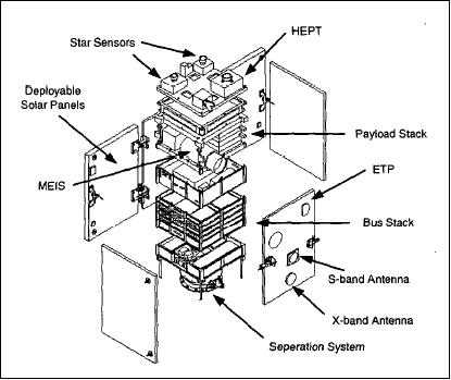
Spacecraft
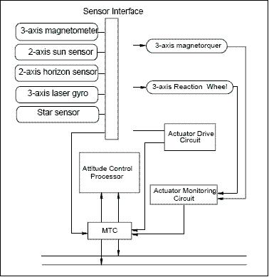
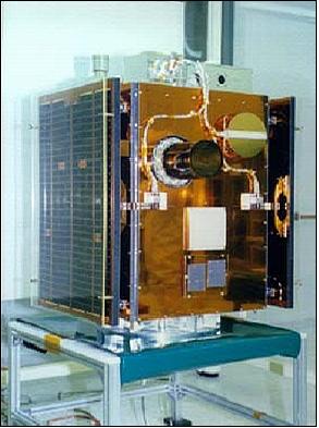
KITSAT-3 is three-axis stabilized providing a pointing accuracy of <0.5º. Attitude of the box-like satellite (495 mm x 604 mm x 852 mm) is sensed by a sun sensor (two-axis), Earth horizon sensor, star sensor (CCD type), fiber optic gyro, and a three-axis magnetometer; control is provided by a three-axis magnetorquer and a reaction wheel as actuators.
The EPS (Electrical Power Subsystem) provides power of 180 W (max). The power conditioning uses an unregulated bus voltage. The battery capacity is 8.6 Ah.
Spacecraft mass = 110 kg, power = 150 W (deployable solar panels). Spacecraft design life of 3 years. 1) 2) 3) 4) 5) 6) 7) 8) 9)

Subsystem | Key features |
ADCS (!Attitude Determination & Control Subsystem) | - 3-axis stabilization based on 4 reaction wheels |
EPS (Electrical Power Subsystem) | - GaAs/Ge solar cells on honeycomb substrate |
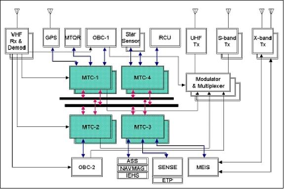
C&DHS (Command & Data Handling Subsystem) | - Two on-board microprocessors (32/16 bit) |
RF Subsystem | - Uplink: 9.6 kbit/s / 1.2 kbit/s VHF TT&C |
Structure & Thermal | - Modular structure |
Spacecraft mass, size | 110 kg, 495 mm x 604 mm x 852 mm |
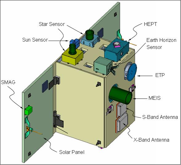
RF communications: VHF receiver at 1200/9600 bit/s, AFSK/FSK modulation, frequency of 148 MHz in uplink. UHF transmitter at 1200/9600 bit/s, AFSK/FSK modulation, frequency of 401 MHz downlink. S-band transmitter at 9.6/38.4 kbit/s, FSK modulation, frequency of 2.2 GHz. X-band transmitter (for imagery transmission) at 3.2 Mbit/s, QPSK modulation, frequency of 8.2 GHz. Onboard image data compression in JPEG, GIF and DPCM. An onboard data storage capability of 10 Gbit is provided (2 Gbit SRAM, 8 Gbit flash memory).
Launch
KITSAT-3 was launched on an ISRO PSLV-C2 launch vehicle as a piggyback payload from SHAR, India, on May 26, 1999 (the prime payload was IRS-P4, also referred to as OceanSat-1 of ISRO, the other secondary payload was DLR-TUBSAT). 10) 11) 12) 13) 14)
Orbit: Sun-synchronous circular orbit, altitude = 720 km, inclination = 98.37º, period = 99.1 minutes, repeat cycle = 67 days.
Mission Status
• The KitSat-3 spacecraft operations were ended in December 2003 after 4 1/2 years of mission service. The battery power had reached a level where further operations of the spacecraft couldn't be maintained. 15) 16)
• The solar panels were deployed on June 24, 1999.
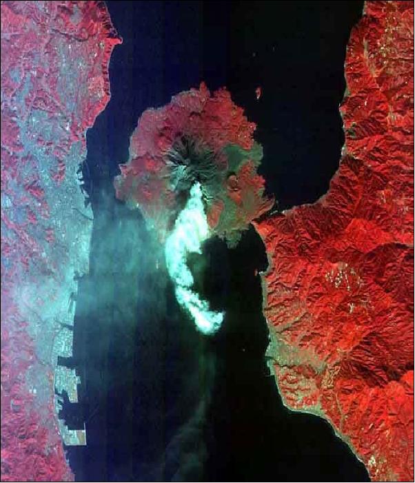
• The spacecraft attitude was first captured and 3-axis stabilized on May 30, 1999. The first image was obtained on May 31, 1999, just 5 days after launch.
Sensor Complement
The instrument payload consists of one remote sensing instrument and an experiment package referred to as SENSE (Space Environment Scientific Experiments), consisting of REME, HEPT, SMAG, and ETP.
MEIS (Multispectral Earth Imaging System)
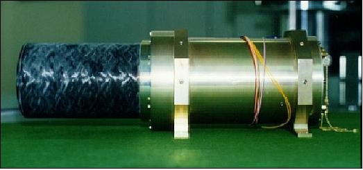
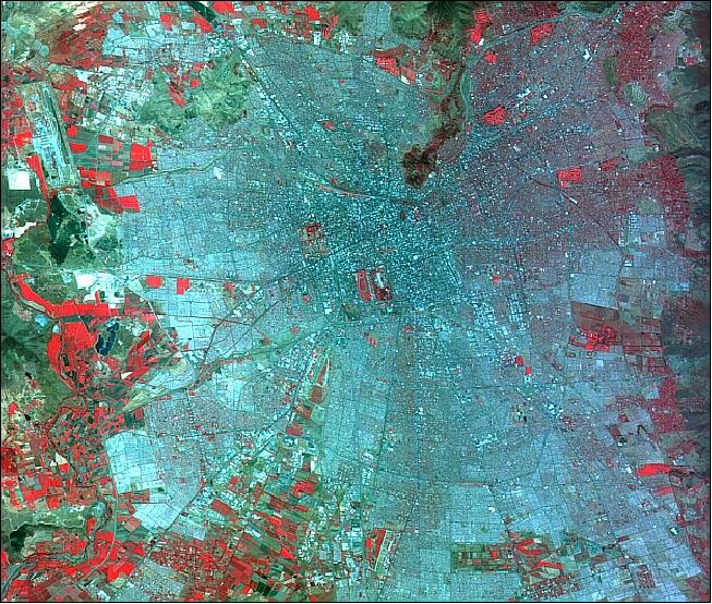
MEIS was developed by SaTReC in cooperation with Stellenbosch University, Stellenbosch, South Africa. The objective is to acquire multispectral high-resolution Earth surface imagery. MEIS is a pushbroom camera consisting of a single 10 cm diameter optical tube assembly (a catadioptric telescope), a lens system, penta-prism with a dichroic color splitter, three vertically mounted linear CCD detectors (TC104 of Texas Instruments), and their clock drivers and output buffers. The camera optics parameters are: 570 mm focal length, 100 mm aperture diameter and f/5.7 relative aperture.
The camera employs a beam splitter and three linear CCD detector arrays with 3456 pixels in the cross-track direction (one CCD per band), offering a swath width of 50 km (FOV=3.8º) with a spatial resolution of 13.8 m (IFOV = 19.1 µrad).
Spectral band coverage: 510-620, 620-690 and 730-900 nm. For operational purposes the imagery is subdivided into managable volumes of data, a scene is defined as 50 km x 30 km (or 3456 pixels x 2048 lines along-track), a maximum of 12 consecutive scenes may be scanned during any one pass. The source data rate is 40 Mbit/s. Further instrument parameters: instrument mass = 6.5 kg, power = 15 W.
Instrument mass, power | 6.5 kg (3 kg for telescope), 15 W |
Imager type | Pushbroom |
Spectral bands (3) | 510-620, 620-690 and 730-900 nm |
IFOV, FOV | 19.1 µrad (corresponding to 13.8 m), 3.8º |
Swath width | 50 km |
Telescope aperture, effective focal length, f number | 10 cm, 570 mm, f/5.7 |
Telescope type | Cassegrain variant made of primary and secondary mirrors and corrective lenses |
Detector | Three linear CCDs (1 per band) each with 3456 pixels |
MTF (Modulation Transfer Function) | 20% at Nyquist frequency |
SENSE (Space Environment Scientific Experiment)
The following devices: REME, HEPT, ETP and SMAG are being referred to as SENSE.
REME (Radiation Effect on Micro-Electronics)
REME was designed to test non-space qualified electronic components, such as memory ICs and discrete components. This experiment consists of two sub-experiments, namely: TDE (Total Dose Effect) and SEU (Single Event Upset) monitoring.
• TDE measures the long-term accumulated ionizing radiation dose (in SiO2) for three locations onboard the S/C. The sensing elements are RADFET dosimeters. Each RADFET sensor consists of a matched pair of p-channel MOSFETs. One of them is biased during exposure, the other remains unbiased. Exposure to radiation causes the formation of trapped holes (positive charge) in the gate oxide, which in turn causes a gradual shift in the threshold voltage with accumulated dose. The radiation shielding effect can be calculated and modeled according to the sensor locations.
• SEU. The objective is to monitor trapped particles in the radiation belts, solar flare protons, and galactic cosmic rays (all of which can cause single-event upsets within microelectronic devices). A series of tests are performed with memory chips to measure the SEU characteristics. Discrete components are connected to appropriate measurement circuits, and variations of their characteristics are monitored together with the total dose measurement.
HEPT (High Energy Particle Telescope)
The objectives are to study the physics of energetic particles in the Earth's radiation belts (sources, sinks, transport, and lifetimes). The HEPT module provides seven measurement channels. The pointable instrument features a cone-shaped structure (funnel) which limits the incident angles of particles to be measured. The signals from four parallel-positioned sensors are combined and processed to identify the energy and type of a particle. Measured pitch angle distributions (pitch angles are calculated using the sensor's look directions and the magnetic field direction, determined by the onboard magnetometer) can be used for developing models of the populations of both the static and dynamic radiation belts.
SMAG (Scientific Magnetometer)
The objectives are to provide look angle information (1º pitch angle resolution) for the particle experiments, to utilize it as a diagnostic tool for the detection of geomagnetic disturbances, to measure low-frequency waves in the ambient environment, and to provide a secondary source for S/C attitude information. SMAG measures the projections of the ambient field in three orthogonal direction with a resolution of about 5 nT.
ETP (Electron Temperature Probe)
The objectives are to measure the electron (plasma) temperature in high latitude regions, in particular in the polar cusp, to study anomalous heating in SAA (Southern Atlantic Anomaly), and to find a relation with other plasma parameters. The electron temperature is determined from the voltage difference between the modulated probe potential and the floating potential.
References
1) Dongseok Shin, Young-Ran Lee, Kyung-In Kang, Dan Keun Sung, ”A Low Cost Ground System for KITSAT-3,” Proceedings of the Euro-Asian Space Week, Published by ESA, CRISP, NUS, Singapore, Nov. 23-27, 1998.
2) H. S. Kim, H. K. Lee, S. D. Choi, ”Command and Data Handling Subsystem for KITSAT-3,” Proceedings of the DASIA '97 Conference on Data Systems in Aerospace, Sevilla, Spain, 26th-29th May 1997, pp. 277-279, 1997.
3) Sungheon Kim, Sungdong Park, Dan Keun Sung and Soon Dal Choi, ”Mission Overview of Engineering Test Satellite, KITSAT-3,” Proceedings of the 9th Annual AIAA/USU Conference on Small Satellites, Logan, UT, USA, Sept. 19-22, 1995.
4) Sungdong Park, S. Kim, D. K. Sung, Soon Dal Choi, ”Mission Analysis for Engineering Test Satellite, KITSAT-3,” Proceedings of the 16th Asian Conference on Remote Sensing (ACRS), Nakhon Ratchasima, Thailand, Nov. 20-24, 1995, Vol. PS-6, pp. 1-7, 1995.
5) https://web.archive.org/web/20150908193412/http://satrec.kaist.ac.kr/english/res_kitsat3.html
6) H: S. Kim, T. J. Chung, N. H. Sung, K. H. Lee, “Design Concept for Autonomous Operation of KitSat-3, an Experimental LEO Microsatellite,” Proceedings of the IEEE Aerospace Conference, Big Sky, MT, USA, March 18-25, 2000,, URL: http://koasas.kaist.ac.kr/bitstream/10203/14622/1/Design%20Concept...
7) Hyunwoo Lee, “Case Study - KITSAT Series Satellites,” URL: http://csplab.kaist.ac.kr/lecture/SatRec2007/lecture_notes/EE807_070605.pdf
8) Ee-Eul Kim, Sungheon Kim, Dan Keun Sung, Soon Dal Choi, “Development of an Engineering Test Satellite, KitSat-3,” Cooperation in Space, Euro-Asian Space Week : where East and West finally meet, Singapore, November 23-27, 1998, URL: http://articles.adsabs.harvard.edu/cgi-bin/nph-iarticle_query?bibcode=1999ESASP.430..453K&db_key=AST&page
_ind=0&data_type=GIF&type=SCREEN_VIEW&classic=YES
9) Sungdong Park, Sungheon Kim, Dan Kenu Sung, Soon Dal Choi, “Mission Analysis for Engineering Test satellite, Kitsat -3,” 16th ACRS (Asian Conference on Remote Sensing), Nakhon Ratchasima, Thailand, Nov. 20-24, 1995, URL: http://www.a-a-r-s.org/acrs/proceeding/ACRS1995/Papers/PLS95-2.htm
10) Sungdong Park, Taejin Chung, Hyunwoo Lee, Yunhwang Jeong, Jinjoong Kim, Younghoon Shin, Dan Keun Sung, and Soon Dal Choi, ”KITSAT-3 Launch and Initial Operations,” Proceedings of the 5th Asia-Pacific Conference on Multilateral Cooperation in Space Technology and Application (APC-MCSTA), Teheran, Iran, Dec.1999
11) Wonkyu Park, Soon Dal Choi, ”Application of KITSAT-3 Images: Automated Generation of Fuzzy Rules and Membership Functions for Lan-cover Classification of KITSAT-3 Images,” Proceedings of ISRS (International Symposium of Remote Sensing), organized by the Korean Society of Remote Sensing (KSRS), Kangnung, Korea, Nov. 3-5, 1999, pp. 48-53
12) Dongseok Shin, Wookhyun Choi, Sunghee Kwak, Tag-Gon Kim, ”KITSAT-3 Image Product Generation System, Proceedings of ISPRS (International Symposium of Remote Sensing), organized by the Korean Society of Remote Sensing (KSRS), Kangnung, Korea, Nov. 3-5, 1999, pp. 43-47
13) B. J. Kim, H. Lee, S. D. Choi, “Three-Axis Reaction Wheel Attitude Control System for KITSAT-3 Microsatellite,” Pergamon, Space Technology, Vol. 16, No 5/6, pp. 291-296, 1996, URL: http://microsat.sm.bmstu.ru/e-library/Algorithms/wss/w1.pdf
14) J. C. Yoon, Y. K. Chang, K. H. Choi, ”Orbit Determination of KITSAT-3 Satellite Using GPS Navigation Solutions”, Journal of the Korean Society for Aeronautical and Space Sciences Vol. 28, No 5, 2000, pp. 61-70
15) Information provided by Tae Seong Jang of SaTReC, Daejeon, Korea
16) Soon D. Choi, “Space Technology Build-up of Korea,” UN/ESCAP Meeting of Eminent Experts on ICST, Bangkok, Thailand, Aug. 3-4, 2006, URL: http://www.unescap.org/idd/events/2006_Eminent_Experts/Presentations/Soon%20Dal%20Choi-%20Space
%20Tech.%20Build-up%20of%20Korea.pdf
The information compiled and edited in this article was provided by Herbert J. Kramer from his documentation of: ”Observation of the Earth and Its Environment: Survey of Missions and Sensors” (Springer Verlag) as well as many other sources after the publication of the 4th edition in 2002. - Comments and corrections to this article are always welcome for further updates (eoportal@symbios.space).