MinXSS (Miniature X-ray Solar Spectrometer)
Non-EO
Space Weather
Quick facts
Overview
| Mission type | Non-EO |
| Launch date | 06 Dec 2015 |
| End of life date | 14 Feb 2019 |
MinXSS (Miniature X-ray Solar Spectrometer) Nanosatellite
Spacecraft Launch Mission Status Sensor Complement MinXSS-2 References
MinXSS is a 3U CubeSat solar physics mission of the CU (University of Colorado) at Boulder, designed to better understand the energy distribution of solar flare SXR (Soft X-ray) emissions and its impact on the Earth's ITM (Ionosphere, Thermosphere, and Mesosphere). This project started in 2011 and heavily involves in particular graduate student team members with scientists and engineers at the Laboratory for Atmospheric and Space Physics (LASP), located on the east campus at CU. 1) 2) 3)
The peak solar energy in the SXR is expected to be emitted near 2 nm; however, only limited spectral measurements are available near that wavelength to verify this expectation. Energy from SXR radiation is deposited mostly in the ionospheric E-region, in the altitude range of ~80 to ~150 km, but the precise altitude is strongly dependent on the SXR spectrum because of the steep slope and structure of the photoionization cross sections of atmospheric gases in this wavelength range.
Despite many decades of solar SXR observations, almost all have been broadband measurements with insufficient spectral resolution to fully understand the varying contributions of emission lines amongst the underlying thermal and non-thermal continua. The MinXSS mission will improve the understanding of how highly variable solar X-rays affect the ITM, advance our knowledge of flare energetics in the SXR, and provide new spectral observations of the solar SXR near the maximum of solar cycle 24.
The educational objective of MinXSS is to train students as the next generation STEM ( Science, Technology, Engineering, and Mathematics) workforce. The students will learn – through formal university classes and with hands-on experience – about scientific instrumentation, satellite technology, and science data analysis and modeling techniques.
Measurement requirements: To address the MinXSS science objective, measurements of the solar SXR irradiance (full-disk, not imaging) with spectral resolution better than 1 nm and with accuracy better than 30%. While simple in concept, the technology to do this in the 1-5 nm range has traditionally been difficult. Grazing-incidence grating spectrometers are only effective longwards of 5-10 nm (e.g., SDO/EVE measures down to 6 nm with 0.1 nm resolution. Bragg crystal spectrometers, often used in the 1960s and 1970s for solar SXR measurements, have extremely high spectral resolution but a very narrow range of about 1 nm, and they are large and heavy instruments. Solid-state (semiconductor) photon-counting detectors work very well for obtaining HXR (Hard X-ray) and gamma ray spectra shorter than 0.5 nm (e.g. RHESSI measures up to 0.4 nm.
SDD (Silicon Drift Detectors) are the novel technology that enable new solar spectral measurements over a wider range in the SXR. The Amptek X123 SDD is a commercial off-the-shelf (COTS) instrument that the project acquired; it was flown on a NASA sounding rocket in 2012 as part of the project's calibration program for the SDO/EVE instrument.
The MinXSS mission is most relevant for the NSF Division of Atmospheric and Geospace Sciences (AGS). In particular, MinXSS directly supports goal number 1 for the NSF Geospace Aeronomy CEDAR(Coupling, Energetics, and Dynamics of Atmospheric Regions) program: to study the "dynamics and energetics of the upper atmosphere, with particular emphasis on the hard to observe region between 80 and 150 km."
Spacecraft
The MinXSS project began as a graduate student project in the Aerospace Engineering Sciences (AES) department at CU and ran through the Spring 2014 semester, with an average of 11 graduate students each semester. The AES department supported the first year of the project, which focused on development of the CubeSat Card Cage design and assembly. The second year was supported by the National Science Foundation (NSF), which enabled the design and manufacture of the first flight prototype. With NSF support in 2013 and subsequent NASA funding in 2014–2016, three MinXSS units have been fabricated (Figure 1): a prototype and two FMs (Flight Models). The flight prototype model included the structure, CDH (Command and Data Handling) custom board, EPS (Electrical Power System) custom board, custom motherboard, custom battery pack, and plastic 3D printed prototypes of the secondary instrument housing and antenna deployment module. The prototype MinXSS has been valuable for early testing and fit checks, and as extra unit for developing flight software in parallel with other build activities. 4) 5)
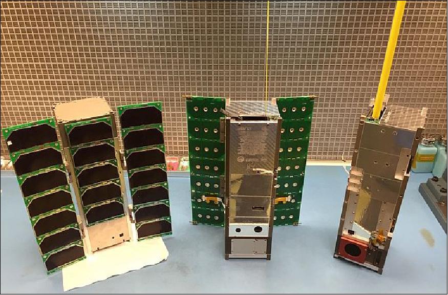
In the current design, MinXSS requires approximately 6 W of orbit-averaged power to fulfill the mission goals. A 3U body-mounted (fixed) solar panel can provide, at most, 7 W of power with triple-junction solar cells, so a deployable solar panel is needed. The team has performed extensive trade studies on numerous solar panel configurations, and has decided to use a double deployed 3U panel array along with a fixed panel to provide about 20 W of power while on the dayside of the orbit, which will provide sufficient orbit-averaged power for any orbit and can adequately handle the peak power demands including charging the battery during the dayside (Ref. 2).
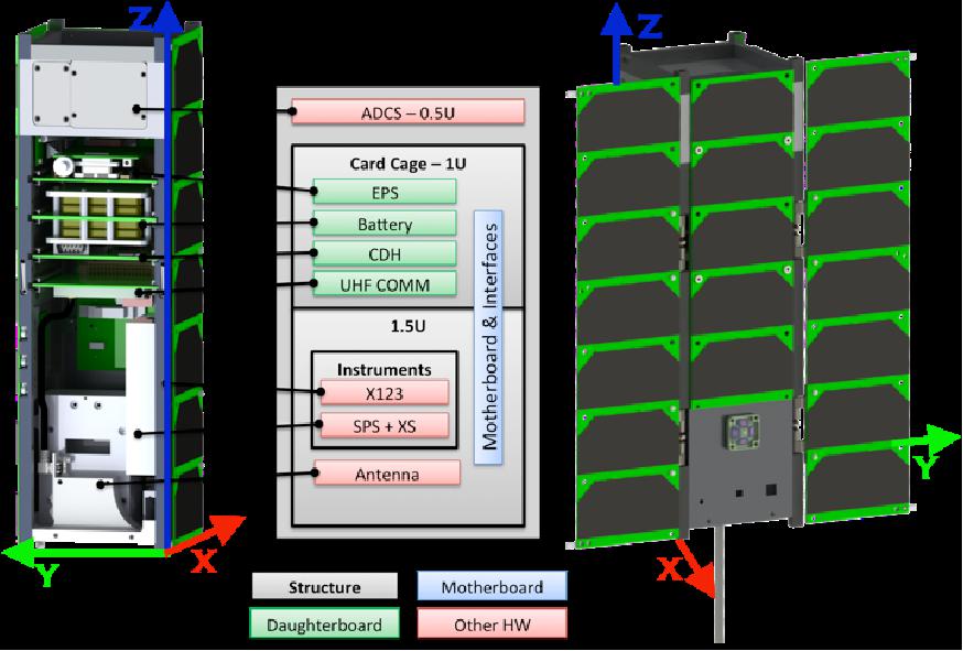
The structure of the nanosatellite is partitioned into three basic blocks (Figure 2): 1U for the instrument (COTS Amptek X123 spectrometer), 1.5U for system electronics, and 0.5U for the ADCS (Attitude Determination and Control Subsystem ). There are two solar arrays to provide 20 W when in sunlight; a body-mounted solar panel (3U surface area: 10 cm x 34 cm) fixed to the solar-oriented side, and a deployed double panel (6U surface area: 20 cm x 34 cm).
The deployable UHF antenna, UHF communication, and EPS (Electrical Power System) are inherited from the CSSWE (Colorado Student Space Weather Experiment), an NSF nanosatellite at CU, which was launched on Sept. 13, 2012.
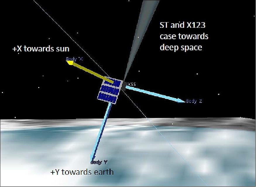
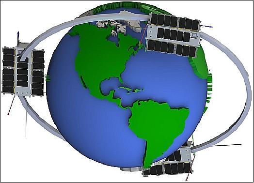
The ADCS will maintain the spacecraft orientation such that the solar panels and instruments are always sun-pointed, and the radiator (on the opposite side from the deployable solar array) is oriented roughly towards zenith (Figure 3).
Subsystem/component | COTS/developed | TRL (Technology Readiness Level) | Heritage |
X-ray Spectrometer | COTS, | 7 | SDO/EVE rocket flight (June 2012) (TRL 9 for XR100-Mars Pathfinder) |
Solar panels | Developed at CU | 8 | NSF CubeSat CSSWE (Sept. 2012) |
ADCS | COTS - Blue Canyon Technologies XACT (fleXible ADCS Cubesat Technology) | 6 | NSC-1 (Near Space Corporation) rocket flight (Oct. 2013) |
Radio | COTS - Lithium-1 Radio | 8 | NSF CubeSat CSSWE (Sept. 2012) |
Antenna | Developed at CU | 8 | NSF CubeSat CSSWE (Sept. 2012) |
C&DH | Developed at CU | 7 | SDO/EVE rocket flight (June 2012) Maven and GOES-R missions |
EPS + Battery | Developed at CU | 8 | NSF CubeSat CSSWE (Sept. 2012) |
SPS (Sun Position Sensor)& XPS (X-ray Position Sensor) | Developed at CU | 7 | GOES design |
CubeSat Card Cage (C3) structure & bus | Developed at CU | 7 | SDO/EVE rocket flight (Sept. 2012) |
Ground Network | Developed at CU | N/A | NSF CubeSat CSSWE (Sept. 2012) |
ADCS (Attitude Determination and Control Subsystem): The MinXSS bus is a 3-axis-controlled nanosatellite to observe the solar SXR spectrum between 0.04 and 3 nm. Use of the XACT (fleXible ADCS Cubesat Technology) unit of BCT (Blue Canyon Technologies). XACT is a standalone 0.5U 3-axis stabilized ADCS unit, featuring a star tracker, coarse sun sensor, IMU (Inertial Measurement Unit), reaction wheels, and torque rods.
Parameter | Performance |
Spacecraft pointing accuracy | ±0.003º (1σ) for 2 axes; ±0.007º (1σ) for 3rd axis |
Spacecraft lifetime | ≥1 year |
Spacecraft orbital altitude range | LEO (160-2000 km) |
Mass of XACT unit, volume | ≤0.7 kg, ≤ 10 cm x 10 cm x 5 cm (0.5U) |
Nominal power, peak power consumption | ≤0.5 W, ≤2.0 W |
Operating voltage | 12 V±2 V |
Data interface | RS-422 (can support I2C and SPI) |
Slew rate (8 kg, 3U CubeSat) | ≥10º/s |
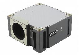
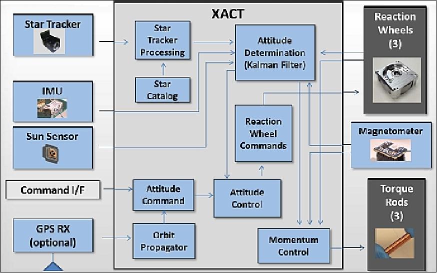
BCT (Blue Canyon Technologies) has developed FlexCore, which is a highly-configurable ADCS that uses a core electronics box (based on the XACT CubeSat ADCS), combined with any of the various reaction wheel sizes in the BCT product line. The FlexCore electronics and software stays the same, regardless of the spacecraft. The wide range of reaction wheel and torque rod sizes supports spacecraft sizes from large CubeSats to 100s of kilograms. The stellar-based attitude determination and control provides accuracy of 0.002º RMS. Features of FlexCore include: multiple nano star trackers with integrated stray-light baffles; 3 or 4 low-jitter reaction wheels; 3 torque rods; GPS receiver; MEMS IMU; MEMS magnetometer; sun sensors; integrated processor and electronics; auto-generated flight software, including star identification, Kalman filter, momentum control, thruster control, and orbit propagation. The table-driven, auto-coded software is easily configured to support any mission, and is delivered to the user fully programmed. 6)
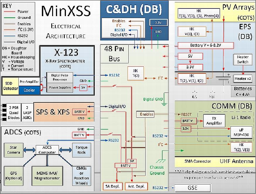
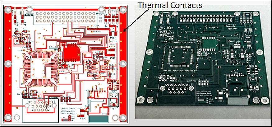
CDH (Command and Data Handling subsystem): The CDH is designed and developed by students. The core processor is the microchip DSPic32 (40 MIPS 16 bit µcontroller). The core processor has a flight history on the SDO/EVE (Solar Dynamics Observatory/EUV Variability Experiment) rocket flight (June 23, 2012) of LASP (Laboratory for Atmospheric and Space Physics) at the University of Colorado. The processor runs on RTOS (slot architecture).
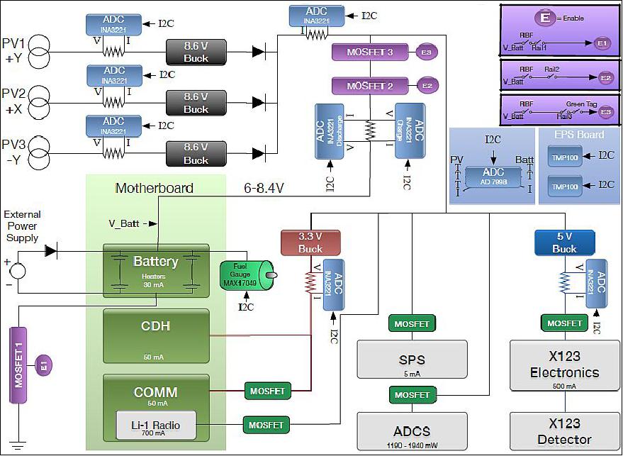
EPS (Electrical Power Subsystem): The nanosatellite uses 28 PV triple junction solar cells distributed among its components. A BCR (Battery Charge Regulator) is used for the battery assembly. Two Li-ion batteries have a storage capacity of 14.8 Whr. The battery cells are connected in series to supply between 6 and 8.5 V (nominally 7.4 V) to the power system.
The project modified the DET (Direct Energy Transfer)EPS design that was inherited from the CSSWE CubeSat to include an additional specially selected resistor to create a PPPT (Pseudo-Peak Power Tracking) system. The extra resistor was chosen to prevent a rapid voltage drop from the solar cells when the battery attempts to draw a large current, namely when the battery state of charge is relatively low right as the spacecraft exits the orbit eclipse.
In the CSSWE and MinXSS EPS design, the output of the solar panels power 8.6 V regulators that then provide regulated 8.5 V power directly to the battery and system. In this DET design, the batteries will charge up to 8.5 V, and there are no supporting electronics required to control the battery charging process. In reality, this simple approach only provides about 50% of the power intended from the solar panels when the battery capacity is low. In particular, when the battery needs more power input (high current) for charging, the high current draw from the solar cells results in much lower voltage, following the standard solar cell current-voltage (I-V) curve. When the solar panel output voltage goes below the minimum input voltage level of the 8.6 V regulator, the regulator turns off. Consequently, the current drops and the solar panel output voltage increases, and the 8.6 V regulator turns back on. This results in a high-frequency on-off regulator oscillation that had the EPS 8.6 V regulators on for only about 50% of the time during the early part of the orbit dayside during mission simulations. The MinXSS solar panels were designed for 80% of peak efficiency at EOL, but the 50% decrease in power was an unacceptable power loss for the nominal power budget.
The solution for MinXSS, without having to redesign or rebuild the EPS board, was to replace the sense resistor on the output of the solar panel regulator with a larger resistance so that the effective current draw out of the solar panel would be limited and thus would not cause
the regulator to turn off. The project refers to this current-limiting resistor for the solar panels as PPPT. Figure 8 shows a simplified version of the PPPT circuit for the MinXSS EPS.
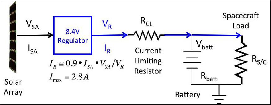
One disadvantage to the PPPT implementation is that there is additional heating of the EPS board because of the larger resistance; however, this extra heating peaks right after exiting eclipse, the precise time when temperatures are cooler and heating is desired anyway. For example, the power loss (heating) in the PPPT current-limiting resistor is estimated to be 2.6 W when the battery voltage is at its lowest value of 7.1 V, decreasing to 0.93 W when the battery voltage is at 7.5 V, and reduces to less than 0.1 W once the battery voltage is above 8.0 V. The primary caveat in the PPPT design is that resistor tuning must be done a priori, and is fixed, whereas maximum PPT (MPPT) systems can tune resistance in real time to maintain the maximum power point on the solar cell I-V curve. The trade studies performed for CSSWE and MinXSS resulted in the selection of a custom DET EPS due to the simplicity of design. Both teams were unaware of the consequential loss of power generation at the time of the original designs. The advantage of the PPPT circuit is that it is only minimally more complex than DET, adding little risk for a large benefit.
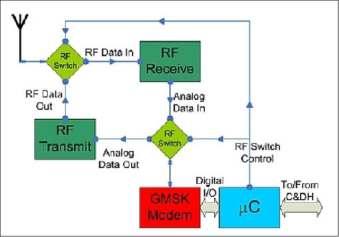
COMM (Communications subsystem): A half-duplex communication scheme is used with two deployable steel-tape monopole antennas connected together with a 180º hybrid for RF communications. This dual monopole configuration has been tested, and exhibits a gain pattern very close to that of a dipole. A GMSK (Gaussian Minimum Shift Keying) modulation chip has been selected to be the heart of the communications board, the SX1231.
The COMM microcontroller (µC) interfaces the C&DH subsystem with a GMSK modem and sends all data received by the C&DH to the GMSK modem to be modulated and transmitted to the GN (Ground Network). The nanosatellite uses a MSP430 microcontroller for the COMM and C&DH subsystems, which enables a common programming environment and reduces interface complexity.
The transceiver operates in the UHF band at 433 MHz (amateur band), which allows cooperation with any number of amateur ground stations across the globe. The transmission data rate is 9.6 kbit/ in downlink and uplink. 7) 8)
The ground station antenna is a M2 MCP436CP30 cross polarized 42 element yagi antenna with a gain of 14.15 dBdc.
The MinXSS nanosatellite has a mass of ~4 kg and a power consumption of 7.3/18.1 W(average/peak).
Development status:
• In the summer of 2015, FM-1 has completed environmental testing and is ready for delivery and launch later in 2015, with deployment expected in early 2016. FM-2 has been built and integrated and is now ready for environmental testing in late 2015 and launch in mid-2016.
Launch
MinXSS-1
The MinXSS-1 nanosatellite was launched as a secondary payload on December 6, 2015 (21:44:57 UTC) on the Cygnus Orbital ATK CRS-4 mission with the ULA Atlas-V-401 vehicle to the ISS (International Space Station). The launch site was SLC-41 (Space Launch Complex-41) at CCAFS (Cape Canaveral Air Force Station), FL. 9) 10) 11)
Note: The Atlas-V vehicle of ULA will provide a launch service for the Orbital ATK Cygnus CRS-4 cargo vehicle to the ISS as a replacement rocket for the Orbital Sciences Antares rocket which is grounded following its catastrophic Oct. 28 explosion on the Orb-3 mission from NASA Wallops. — The Orb-4 launch also marks ULA's first launch to the ISS. It may be followed by another Cygnus launch atop an Atlas V in 2016 as Orbital works to bring the Antares back into service. 12)
Secondary payloads:
- Flock-2e, 12 3U CubeSats of Planet Labs
- CADRE, a 3U CubeSat technology mission of the University of Michigan
- MinXSS-1, a 3U CubeSat solar physics mission of the CU (University of Colorado) at Boulder
- NODES (Network & Operation Demonstration Satellite), two 1.5 CubeSats of NASA
- STMSat-1 (Saint Thomas More School Satellite), Arlington, VA, 1U CubeSat.
- SIMPL (Satlet Initial-Mission Proofs and Lessons), a microsatellite of NanoRacks. SIMPL is a modular, hyper integrated satellite designed to provide complete satellite functionality in a nanosatellite scale. It will be the first NanoRacks microsatellite deployed from the space station and the first propulsion-capable satellite deployed from the NanoRacks MicroSat Deployer, known as Kaber. The commercial deployer system aims to address the growing market of customers wanting to deploy microsatellites from the ISS orbit.
Orbit: Near-circular orbit, altitude of ~400 km, inclination =51.6º.
MinXSS FM-1 will be deployed from the NRCSD (NanoRacks CubeSat Deployer) on the ISS in February 2016, where it will have an expected 5–12 month orbital lifetime, dependent on atmospheric conditions. MinXSS FM-2 is being planned for a higher altitude, longer mission in a sun-synchronous polar orbit via a launch on the Skybox Minotaur C launch in 2016.
MinXSS-2
On 3 December 2018, MinXSS-2 was launched on a SpaceX Falcon 9 as part of the SSO-A ride-share mission to sun-synchronous low earth orbit. The launch site was VAFB (Vandenberg Air Force Base), CA. 13)
Orbit: Sun-synchronous orbit, altitude of 575 km, inclination of 97.75º, LTDN (Local Time on Descending Node) =10:30 hours.
At this altitude, MinXSS-2 is expected to have significantly less atmospheric drag and thus a longer mission life. The goal is a 5-year mission. With orbital lifetime extended, the next most likely limiting factors on mission lifetime are the long term operation of the battery and the reaction wheels.
Mission Status
• April 17, 2019: The second Miniature X-ray Solar Spectrometer (MinXSS-2) CubeSat, which was launched on 3 December 2018, builds on the success of MinXSS-1, which flew from 16 May 2016 to 06 May 2017. The science instrument is more advanced – now capable of greater dynamic range with higher energy resolution. More data will be captured on the ground than was possible with MinXSS-1 thanks to a sun-synchronous, polar orbit and technical improvements to both the spacecraft and the ground network. Additionally, a new open-source beacon decoder for amateur radio operators is available that can automatically forward any captured MinXSS data to the operations and science team. While MinXSS-1 was only able to downlink about 1 MB of data per day corresponding to a data capture rate of about 1%, MinXSS-2 will increase that by at least a factor of 6. This increase of data capture rate in combination with the mission's longer orbital lifetime will be used to address new science questions focused on how coronal soft X-rays vary over solar cycle timescales and what impact those variations have on the earth's upper atmosphere. 14)
• January 2018: MinXSS-1 was deployed from ISS on 16 May 2016 and obtained thousands of new solar X-ray spectra before its reentry on 6 May 2017. 15) The project was in normal science operations up until just 2 days before burn up; when the team received telemetry informing them that parts of the spacecraft hit temperatures > 300 ºC, MinXSS-1 had been on orbit for 354 days, 16 hours, 32 minutes, and 0 seconds. Over 40 graduate students, 3 undergraduate students, and one high school student have worked on MinXSS-1. 16) 17)
• February 21, 2017: The MinXSS-1 continues at full operational status. Science data are still being collected and operations are all automated. The altitude is down to 338 km but so far the ADCS has had no problem dumping drag-induced momentum. JSpOc anticipates reentry in late May. 18)
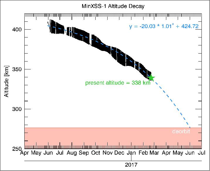
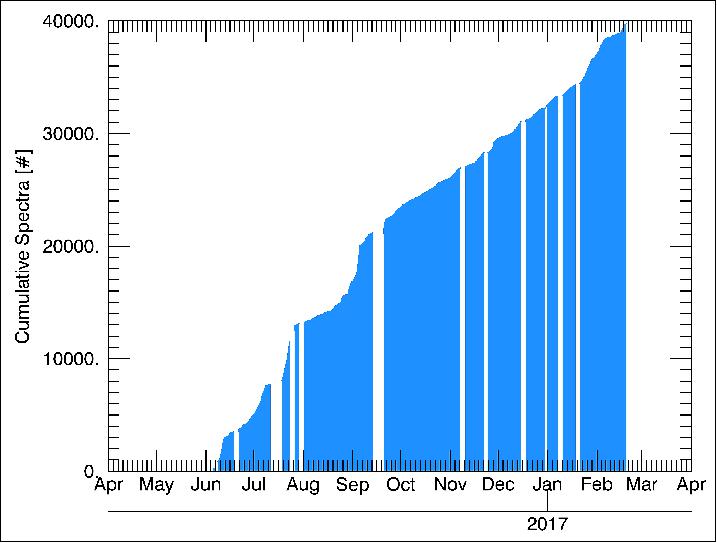
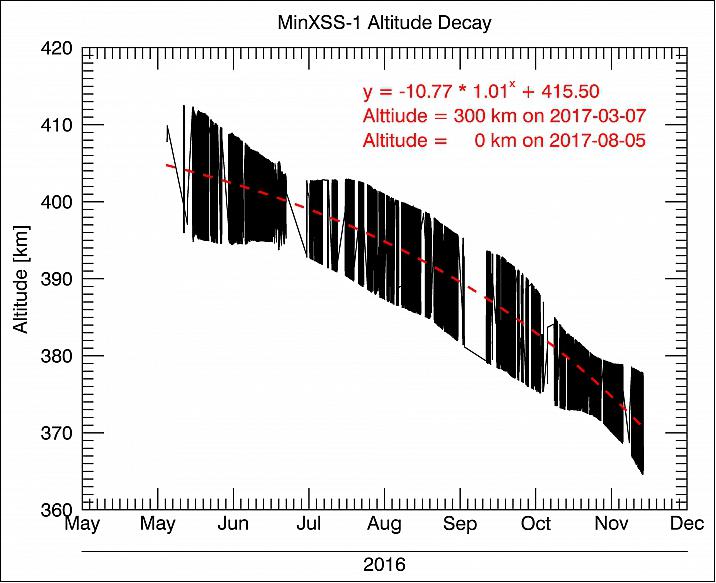
• November 16, 2016 marked 6 months on orbit for MinXSS-1 (deployed from the ISS on May 16, 2016). Operations are continuing nominally and the team are still collecting science data. The project team has been tracking the altitude decay of the spacecraft and projecting how much longer the mission may last. The bottom line: a few more months, probably. 19)
- The plot of Figure 15 shows the actual MinXSS-1 altitude in black and an exponential fit to that data in red. The team uses that fit to extrapolate to 300 km (where the mission will likely be over as the spacecraft burns up in the atmosphere) and 0 km, when you can be absolutely sure it's over.
• November 6, 2016: So far, the MinXSS CubeSat has observed more than 40 C-class and seven M-class solar flares. The largest flares observed by the spacecraft to date occurred on July 23, 2016 with an M5.0 flare that peaked at 2:11 GMT, an M7.6 flare that peaked at about 5:16 GMT, and an M5.5 flare that peaked a few minutes later. 20)
- Besides conducting solar flare observations, MinXSS also serves as a technology demonstrator of the Blue Canyon Technologies XACT attitude determination and control system (ADCS), one of the only commercially available 3-axis ADCSs for CubeSats.
• July 1, 2016: The MinXSS nanosatellite was deployed successfully from the ISS on May 16, 2016 and its commissioning was completed on June 9, 2016 — and the nanosatellite status is now in support of normal science operations. The primary goal for MinXSS is to study the solar soft X-ray (SXR) spectra to help understand coronal heating and energetic events, such as solar flares, and to further understand how the solar SXR variability impacts Earth's upper atmosphere. The MinXSS spacecraft and instruments are healthy and are routinely observing the Sun every orbit. This MinXSS- 1 mission is expected to be 6-12 months long due to starting at the ISS altitude of about 400 km, but MinXSS-2, scheduled to launch this fall into an orbit at 500 km altitude, could have a 5-year mission. The Sun has been relatively quiet in June; nonetheless, MinXSS-1 has observed five flares with the largest being the C6.5 flare on June 11, 2016. 21)
- The MinXSS-1 mission is also verifying new space technology. One is the Amptek X123 SDD for solar SXR spectral measurements in the 0.5-30 keV range (0.04-2.5 nm) with 0.15 keV energy resolution. Comparison of the X123 spectra integrated over the GOES XRS-B 1- 8 A0 band is the primary topic of this MinXSS Science Nugget. In addition, the MinXSS mission is the first flight of the BCT (Blue Canyon Technologies) ADCS (Attitude Determination and Control Subsystem) that is designed for 3-axis control of nanosatellites with 10 arc sec precision. Another new flight technology is the SPS (Solar Position Sensor) using the GOES-R EXIS custom electrometer; the SPS has validated the BCT ADCS solar pointing precision to be about 8 arcsec with an uncertainty of 2 arcsec.
- The MinXSS solar SXR spectral irradiance measurements are important for filling the spectral gap between the EUV (Extreme Ultraviolet) spectral irradiance measurements by SDO (Solar Dynamics Observatory) EVE (Extreme ultraviolet Variability Experiment) and the hard X-ray (HXR) spectral measurements by RHESSI (Reuven Ramaty High Energy Solar Spectroscopic Imager). The SXR range is of particular interest for flares that are expected to have peak increases near 1 keV (1.2 nm). The rest of the discussion concerns the comparison of these early X123 measurements to the GOES XRS (X-Ray Sensor) broad band measurement.
- The GOES XRS-B 1-8 A0 band measurement has been the reference for classifying X-ray flare magnitude since the 1970s, and yet, the previous GOES XRS instruments have not had a full spectral calibration. For consistency of flare magnitude, the GOES XRS results have not been adjusted from the original level over the many different GOES missions. NOAA's analysis of the GOES XRS data indicates that the XRS-B 1-8 A0 band probably needs to be divided by 0.7 to be on a more accurate irradiance scale and that the XRS-A 0.5-4 A0 band probably needs to be divided by 0.85. The team apply these scaling factors for the following comparison with MinXSS SXR measurements.
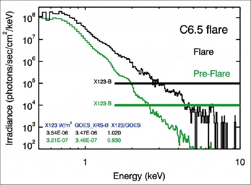
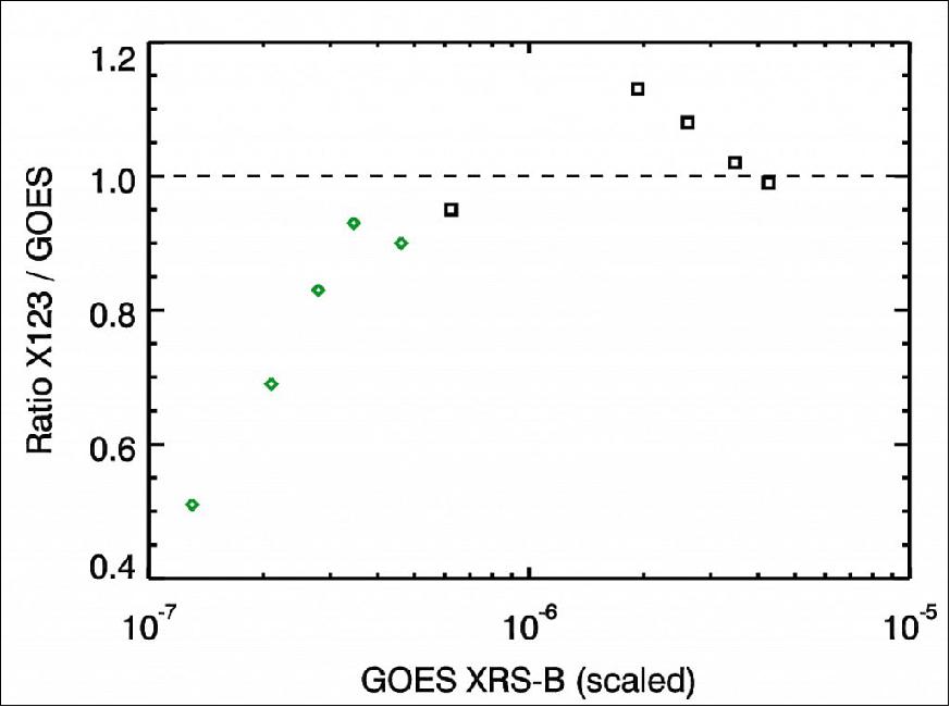
- The solar observations by MinXSS X123 can provide a spectral calibration for the GOES XRS because MinXSS instruments had pre-flight calibrations at NIST with an accuracy of about 10%. The team also note that the next generation GOES-R XRS has also had pre-flight NIST calibrations, and the first GOES-R series satellite launch is planned for this fall. The X123 solar SXR spectral irradiance, which are considered preliminary until its Level 1 product is released, is integrated over the 1-8 A0 range (1.55-12.4 keV) to obtain "X123-B" irradiance in units of W/m2 and then compared to GOES XRS-B irradiance values that have already been scaled by the NOAA 0.7 factor. Table 3 lists these comparisons for the pre-flare and flare peak irradiances from five events. Figure 16 shows the X123 solar SXR spectra for the C6.5 flare on June 11, 2016 as an example for the data used to make Table 3.
2016 Date | Flare Class | Pre-Flare | Flare Peak | ||||
X123-B | GOES-B | X123/GOES | X123-B | GOES-B | X123/GOES | ||
06-09 | C1.5 | 1.45 x 10⁻⁷ | 2.10 x 10⁻⁷ | 0.69 | 2.18 x 10⁻⁶ | 1.93 x 10⁻⁶ | 1.13 |
06-11 | C6.5 | 3.21 x 10⁻⁷ | 3.46 x 10⁻⁷ | 0.93 | 3.54 x 10⁻⁶ | 3.47 x 10⁻⁶ | 1.02 |
06-12 | C1.8 | 4.13 x 10⁻⁷ | 4.61 x 10⁻⁷ | 0.90 | 2.83 x 10⁻⁶ | 2.61 x 10⁻⁶ | 1.08 |
06-13 | C3.0 | 2.30 x 10⁻⁷ | 2.79 x 10⁻⁷ | 0.83 | 4.26 x 10⁻⁶ | 4.26 x 10⁻⁶ | 0.99 |
06-25 | B4.4 LDE | 6.59 x 10⁻⁸ | 1.30 x 10⁻⁷ | 0.51 | 5.92 x 10⁻⁷ | 6.23 x 10⁻⁷ | 0.95 |
- The average ratio of X123 integrated irradiance to GOES XRS-B 1-8 A0 irradiance is 1.03 with standard deviation of 0.07 for the flare peak comparison and is consistent with the comparison of the rocket X123 measurements to GOES by Caspi, Woods, & Warren (2015). However, the X123/GOES ratio for the pre-flare comparison has a downward trend for the lower irradiance values as illustrated in Figure 17. Because the data processing for the GOES XRS irradiance assumes a fixed solar spectrum, it is not too surprising to find that the ratio has a trend for the pre-flare comparison whose spectra can be described by plasma at cooler temperatures. On the other hand, the flare peak spectra, except for the B4.4 LDE (Long Duration Event), are more consistently at the same plasma temperature of 4-6 MK and thus have similar ratio values. This result appears to confirm that the NOAA recommended 0.7 calibration factor is appropriate for C-class flares, and possibly also for larger flares if their plasma temperatures are also about 4-6 MK. The team do underscore that these results are preliminary and that this comparison is with only ten SXR spectra.
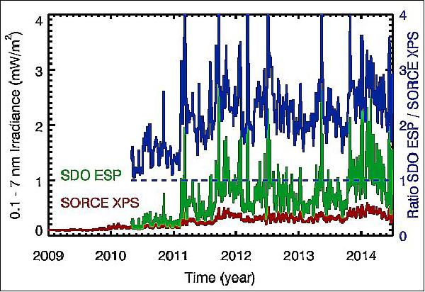
- This result also emphasizes the importance of processing broad band measurements with appropriate SXR spectra to obtain more accurate irradiance values. The new MinXSS solar SXR spectra can benefit the analysis of GOES XRS data and also several other broad band SXR photometers: XPS on TIMED-SEE and SORCE, ESP on SDO-EVE, SOHO-SEM, SNOE-SXP, and PROBA 2-LYRA.
• June 30, 2016: In its first ever flight, the XACT (fleXible ADCS CubeSat Technology) attitude control system from BCT (Blue Canyon Technologies) is providing high-performance guidance, navigation, and control to the orbiting MinXSS (Miniature X-ray Solar Spectrometer) nanosatellite. 22)
- The XACT unit provides state-of-the-art attitude control for small spacecraft like MinXSS. On-orbit telemetry from the XACT unit and independent spacecraft instrumentation indicates a 1σ cross-axis pointing error of < 8 arcseconds, which is less than the width of the Empire State Building as viewed from Los Angeles .
- BCT has developed a range of high-performance attitude control system products that can support Cubesats to ESPA-class and beyond. By leveraging high reuse of flight-proven electronics and software, and high-volume manufacturing, the XACT, XACT-Core, and FlexCore attitude control systems provide a cost-effective solution for the growing small satellite market(Ref. 6).
• On May 16, 2016, the MinXSS nanosatellite was deployed from the ISS to begin its journey into space (NanoRacks deployment services). The NASA-funded MinXSS , built and operated by University of Colorado Boulder students and faculty at the LASP (Laboratory for Atmospheric and Space Physics) and the AES (Aerospace Engineering Sciences Department), studies emissions from the sun that can affect our communications systems. 23) 24)
- MinXSS will operate for up to 12 months. The CubeSat observes soft X-rays from the sun, which can disrupt Earth's upper atmosphere and hamper radio and GPS signals traveling through the region. The intensity of the soft x-ray emissions emitted from the sun is continuously changing over a large range – with peak emission levels occurring during large eruptions on the sun called solar flares.
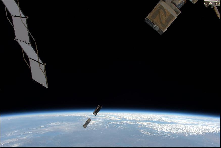
• March 21, 2016: So far MinXSS nanosatellite has not been deployed. The project is experiencing delays. The current best estimate is the first week of April. The NRCSD (NanoRacks CubeSat Deployer) will be used for the MinXSS deployment. The ground station computers have been upgraded from the previous CSSWE mission. 25)
Sensor Complement
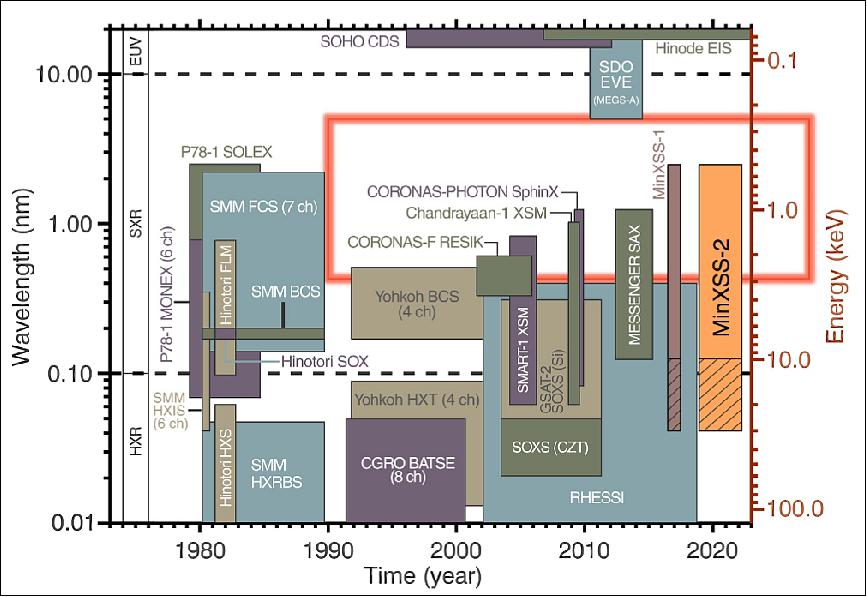
Background: There is a rich history of solar SXR (solar Soft X-Ray) spectral observations over the past three decades, but with a significant gap of spectrally resolved measurements in the 0.4–6 nm range.1 There were many new discoveries about solar flares during the 1980s using solar SXR spectral measurements from the DoD STP P78-1 mission (launch in 1979), NASA's SMM (Solar Maximum Mission, launch 1980), and the JAXA Hinotori satellites. For example, Doschek provides results about flare temperatures, electron densities, and elemental abundances for some flares during these missions. 26)
A review of flare observations from Yohkoh and the CGRO (Compton Gamma Ray Observatory), for the hard (higher energy) X-ray (HXR) range, is provided by Sterling et al.27) These earlier missions laid a solid foundation for studies of flare physics and flare spectral variability that the RHESSI (Reuven Ramaty High Energy Solar Spectroscopic Imager) and the SDO (Solar Dynamics Observatory) continue today for the HXR and EUV ranges, respectively. 28) 29) With solar flare spectral variability expected to peak near 2 nm, in a range not currently observed by any spectrometer, MinXSS measurements of the solar SXR irradiance will provide a more complete understanding of flare variability in conjunction with measurements from RHESSI and SDO EUV Variability Experiment (EVE).30) 31)
There are also nearly four decades of broadband (5-10 nm wide) SXR measurements that do not provide spectrally resolved measurements. The very limited spectral information from these broadband measurements cannot quantify the specific spectral energy distribution, nor directly quantify the varying contributions of emission lines (bound-bound) amongst the thermal radiative recombination (free-bound) and thermal and non-thermal bremsstrahlung (free-free) continua. These broadband measurements include, among others, the two GOES XRS (X-Ray Sensor) channels covering a combined band of 1.6–25 keV (0.05–0.8 nm) and the even broader band of 0.2–12 keV (0.1–7 nm) from several missions, including the Yohkoh SXT (Soft X-ray Telescope, 1991–2001), Student Nitric Oxide Experiment (SNOE, 1998–2002), Thermosphere-Ionosphere-Mesosphere Energetics and Dynamics (TIMED, 2002–present), the Solar Radiation and Climate Experiment (SORCE, 2003–present), and SDO (2010–present). 32) 33) 34) 35) 36)
Broadband measurements of solar SXR instruments have helped to resolve an outstanding difference between ionospheric models and measurements, such as the electron density from the Haystack Observatory incoherent scatter radar at Millstone Hill. In particular, the SNOE solar measurements were able to resolve the factor-of-4 difference between models and measurements because the SNOE data indicated much more SXR irradiance than had been previously thought. 37)
Additional broadband SXR measurements have been made since then; however, differences still remain in understanding solar SXR spectral distribution and atmospheric photoelectron flux. While smaller, these discrepancies are still as large as a factor of 2 at some wavelengths, as shown in Figure 19; the lack of spectral resolution in the SXR range is thought to be the culprit for most of these disagreements. For example, Peterson et al. show that discrepancy between photoelectron measurements and models were significantly improved with new EUV spectral measurements down to 6 nm, and the team anticipate further improvement with new solar SXR spectral measurements and atmospheric modeling with data from MinXSS due to its ability to measure all wavelengths in its spectral range simultaneously and with the relatively high spectral resolution of 0.15 keV FWHM.14
X123 (X-ray Spectrometer)
The science objective of MinXSS is to better understand the solar irradiance energy distribution of solar flare SXR (Soft X-Ray) emission and its impact on Earth's ITM (Ionosphere, Thermosphere, and Mesosphere). Energy from SXR radiation is deposited mostly in the ionospheric E-region, from ~80 to ~150 km, but the altitude is strongly dependent on the SXR spectrum. This wavelength dependence is due to the steep slope and structure of the photoionization cross sections of atmospheric gases in this wavelength range. The main reason that Earth's atmospheric cross section changes so dramatically in this range is due to the K-edges of O at 0.53 keV (2.3 nm) and of N at 0.4 keV (3.1 nm). Figure 20 shows two different solar SXR spectra. Although they have the same 0.1-7 nm integrated irradiance values, their peak energy deposition near the mesopause has a separation of about 5 km. This separation is considered significant because it is about one scale height near 100 km, it is critical to E-region electrodynamics, and the mesopause, the coldest region of the atmosphere, is a critical transition between the middle and upper atmosphere.

Instrument: The MinXSS science measurements will be achieved using the commercially available X123-SDD (Silicon Drift Detector) advanced X-ray spectrometer of Amptek which has an active area of 25 mm2, an effective Si thickness of 0.5 mm, an 8 µm thick Be (beryllium) filter on the detector vacuum housing, an active 2 stage TEC (Thermoelectric Cooler) on the detector, and sophisticated MCA (Multichannel Analyzer) detector electronics. This commercially available handheld X-ray spectrometer was recently flown on a sounding rocket and demonstrated its ability to operate in space.
Key to achieving our science goals is accurate pointing control and knowledge. With the wide field of view of the X123 spectrometer (±4°), the pointing requirements for MinXSS are only 2° (3σ) accuracy and 0.05° (3σ) knowledge.
Features of the X123 science instrument: 38)
• Observes the soft X-ray solar spectrum from <1 keV (>12 Å) to >5 keV (<2.5 Å)
- Resolution: < 0.5 keV
- Accuracy: < 30%
- Measures in a ‘gap' of current knowledge.
• Complete package: silicon-drift detector, thermoelectric cooler, preamp, digital pulse processor and power supplies
• Photon counter, pulse pile-up rejection, multi-channel analyzer (creates spectra).
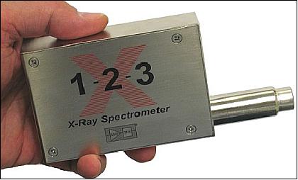
Background: The Amptek X123 (X-ray Spectrometer), a payload flown on the NASA SDO/EVE (Solar Dynamics Observatory/Extreme ultraviolet Variability Experiment) calibration sounding rocket in June 2012 (an underflight of the SDO satellite mission), will be flown again in October 2013; it is the same one that is being integrated into MinXSS. This X123 instrument has also been taken to the SURF (Synchrotron Ultraviolet Radiation Facility) of NIST (National Institute of Standards and Technology) for calibration. Hence, the primary science instrument onboard MinXSS will be fully calibrated and proven in flight. 39)
MinXSS-2 (Miniature X-ray Solar Spectrometer-2)
MinXSS-2 is a copy of the MinXSS-1 (MinXSS-2 was originally built at same time as MinXSS-1), but the project introduced some improvements for MinXSS-2, with the most important being the upgrade of the X123 solar X-ray spectrometer to the Amptek X123 SDD version that has improved energy resolution for the X-ray spectrum. A new UHF ground station at the University of Alaska in Fairbanks has also been added, meaning a higher data downlink capability for this SSO mission. The much higher altitude for MinXSS-2 will allow for a longer mission of 5 years, versus the limitation of ISS-altitude for MinXSS-1 that limited the MinXSS-1 mission to a lifespan of 11 months. This mission is supported by NASA's Heliophysics Division. 40)
Development Status
• September 9, 2018: The MinXSS-2 mission improves several aspects of MinXSS-1. 41)
- The primary science instrument, an Amptek X123 silicon drift detector, has been upgraded with higher energy resolution and greater dynamic range. Hence, it will be able to resolve spectral lines better, as well as to observe larger solar flares without saturating the detector.
- An option in the flight radio has been enabled to transmit at 19.2 kbit/s in addition to the default 9.6 kbit/s. This will allow the team to downlink more data than it was possible on MinXSS-1.
- MinXSS-2 can store commands onboard that will be executed at particular times. This can be used to downlink over any other ground station that the team have coordinated with.
- MinXSS-2 will follow a sun-synchronous orbit. This high latitude of the orbit implies very good alignment with the ground station in Alaska, leading to more long duration passes each day there.
- Moreover, the orbit of MinXSS-2 will be at higher altitude: 575 km instead of the 400 km that MinXSS-1 started with. At such an altitude, the atmospheric drag will be diminished, allowing for a longer lifespan of the satellite. The team expect to operate MinXSS-2 for about 5 years, compared with just 1 year for MinXSS-1.
Because MinXSS-2 is expected to collect a significant amount of novel data, the team decided to expand the science objectives. Consequently, more co-investigators have been involved in the project in order to address these objectives.
A five-year mission allows the team to observe of a significant part of the 11-year solar cycle, such that the scientific questions that they are aiming to find answers to are:
1) How do soft X-ray (SXR) flare energetics change with different size active regions / magnetic complexity over the solar cycle?
2) What are the differences in Earth's ionosphere and thermosphere responses to the solar SXR radiation during different solar cycle phases?
3) Do the coronal heating processes, plasma temperature, and composition change for active regions during the different solar cycle phases?
The list of investigators on MinXSS-2 is:
- Dr. Thomas N. Woods (principal investigator; CU/LASP)
- Dr. Amir Caspi, SwRI (Southwest Research Institute)
- Dr. Phillip Chamberlin (CU/LASP)
- Dr. Andrew Jones (CU/LASP)
- Mr. Rick Kohnert (CU/LASP)
- Dr. James Paul Mason, NASA/GSFC (Goddard Space Flight Center)
- Dr. Scott Palo (CU Aerospace Engineering Sciences)
- Dr. Stanley Solomon, High Altitude Observatory / NCAR (National Center for Atmospheric Research)
- Dr. Harry Warren, NRL (Naval Research Laboratory).
Solar X-ray Spectrometer X123 SDD (Silicon Drift Detector)
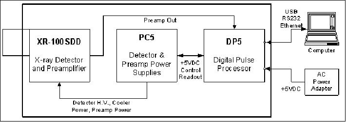
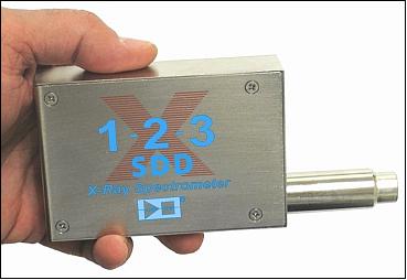
The X-123SDD represents the culmination of years of electronics and X-ray detector innovation and development at Amptek. The team remained focused on creating small, low power, high performance instruments while keeping them simple to operate. The X-123SDD epitomizes this philosophy by providing in a single package the XR-100SDD Silicon Drift X-Ray Detector and its Charge Sensitive Preamplifier; the DP5 Digital Pulse Processor (DPP) with pulse shaper, MCA, and interface; and the PC5 Power Supply. All that is needed is a +5 Volts DC input and a USB, RS-232 or Ethernet connection to the computer. 42)
Instrument features:
• Compact integrated system
• Simple to Operate
• Small Size: 7 x 10 x 2.5 cm
• Low Power: 2.5 W
• Low mass: 180 gram
• USB, RS-232, and Ethernet communication.
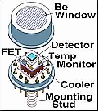
The X-123SDD uses a silicon drift detector (SDD) similar to a Si-PIN photodiode but with a unique electrode structure to improve energy resolution and increase count rates. The SDD is mounted on a thermoelectric cooler along with the input FET and coupled to a custom charge sensitive preamplifier. The thermoelectric cooler reduces the electronic noise in the detector and preamplifier but the cooling is transparent to the user: it operates like a room temperature system.
The pulse processor is the DP5, a second generation digital pulse processor (DPP) which replaces both the shaping amplifier and MCA found in analog systems. The digital technology improves several key parameters:
4) Better performance, specifically better resolution and higher count rates
5) Greater flexibility since more configuration options are available and selected by software
6) Improved stability and reproducibility.
The DPP digitizes the preamplifier output, applies real-time digital processing to the signal, detects the peak amplitude, and bins this in its histogram memory. The spectrum is then transmitted to the user's computer. The PC5 supplies the power to the detector, including low voltages for the preamps, high voltage to bias the detector, and a supply for the thermoelectric cooler which provides closed loop control with a maximum temperature differential of 85 °C. All of these are under software control. The X-123SDD input power is an unregulated +5 VDC with a current of about 300 mA.
The complete system is packaged in 7 x 10 x 2.5 cm3 aluminum box. The detector is mounted on an extender, with lengths from 0 to 9" (vacuum flanges are available). In its standard configuration only two connections are required: power (+5 VDC) and communications (USB, RS232, or Ethernet). An auxiliary connector provides several additional inputs and outputs used if the X-123SDD will be integrated with other equipment. This includes an MCA gate, timing outputs, and eight SCA outputs. The X-123SDD is supplied with our DPPMCA data acquisition and control software. It also includes an Application Programming Interface (API) DLL to integrate the unit with custom software. Options include software for analyzing X-ray spectra, vacuum accessories, several collimation and mounting options, and X-ray tubes to complete a compact system for X-ray fluorescence.
References
1) S. Palo, T. Woods, X. Li, J. Mason, M. Carton, A. Caspi, A. Jones, R. Kohnert, S. Solomon, "MinXSS: A Three-Axis Stabilized CubeSat for Conducting Solar Physics," 5th European CubeSat Symposium, Royal Military Academy, VKI (Von Karman Institute), Brussels, Belgium, June 3-5, 2013
2) Thomas N. Woods, Amir Caspi, Phil Chamberlin, Andrew Jones,Rich Konert, Xinli Li, Scott Palo, Stanley Solomon, "MinXSS - Miniature X-ray Solar Spectrometer (MinXSS) CubeSat Mission," Submitted to NASA on August 15, 2013, URL: http://www.pinheadinstitute.org/wp-content
/uploads/2014/07/MinXSS_Proposal2013_NASA.pdf
3) Amir Caspri, Thomas N. Woods, Harry P. Warren, "New observations of the solar 0.5-5 keV sift X-ray spectrum," The Astrophysical Journal Letters, Vol. 802, No 1, 2015, doi:10.1088/2041-8205/802/1/L2, URL of abstract: http://iopscience.iop.org/2041-8205/802/1/L2/pdf/2041-8205_802_1_L2.pdf
4) James P. Mason, Thomas N. Woods, Gregg Allison, Matthew L. Cirbo, Seth Folley, Andrew Jones, Rick Kohnert, Xinlin Li, Christopher Moore, Amir Caspi, Scott Palo, "Miniature X-Ray Solar Spectrometer (MinXSS) - A Science-Oriented, University 3U CubeSat," Proceedings of the 29th Annual AIAA/USU Conference on Small Satellites, Logan, Utah, USA, August 8-13, 2015, paper: SSC15-III-6, URL: http://digitalcommons.usu.edu/cgi/viewcontent.cgi?article=3182&context=smallsat
5) Karen C. Fox, "NASA-Funded Mission Studies the Sun in Soft X-Rays," NASA, March 24, 2015, URL: http://www.nasa.gov/content/goddard
/nasa-funded-mission-studies-the-sun-in-soft-x-rays/#.VRfVM-Huz_U
6) Daniel Hegel, "FlexCore: Low-Cost Attitude Determination and Control Enabling High-Performance Small Spacecraft," Proceedings of the 30th Annual AIAA/USU SmallSat Conference, Logan UT, USA, August 6-11, 2016, paper: SSC16-X-7, URL: http://digitalcommons.usu.edu/cgi/viewcontent.cgi?
article=3400&context=smallsat
7) Xinlin Li, Scott Palo, Shri Kanekal, Rick Kohnert, Gail Tate, Vaughn Hoxie, David Gerhardt, Lauren Blum, Quintin Schiller, "The Colorado Student Space Weather Experiment (CSSWE) - CSSWE COM System," 9th Annual Spring CubeSat Developer's Workshop, Cal Poly State University, San Luis Obispo, CA, USA, April 18-20, 2012, URL: https://web.archive.org/web/20190716173749/http://mstl.atl.calpoly.edu:80/~bklofas/Presentations/DevelopersWorkshop2012/CHDC_Palo_CSSWE.pdf
8) Xinlin Li, Scott Palo, Rick Kohnert, David Gerhardt, Lauren Blum, Quintin Schiller, Drew Turner, Weichao Tu, Nathan Sheiko, Christopher S. Cooper, "Colorado Student Space Weather Experiment: Differential flux measurements of energetic particles in a highly inclined low Earth orbit," Dynamics of the Earth's Radiation Belts and Inner Magnetosphere, Geophysical Monograph Series, Vol. 199, edited by D. Summers et al., pp. 385-404, 2012, AGU, Washington, D. C., doi:10.1029/2012GM001313, URL: http://lasp.colorado.edu/~lix
/paper/AGU-Mono/2012GM001313-SU-Li.pdf
9) Ken Kremer, "Spectacular Blastoff of Atlas Cygnus Ignites Restart of American Cargo Missions to ISS," Universe Today, Dec. 6, 2015, URL: http://www.universetoday.com/123734/spectacular-blastoff-
of-atlas-cygnus-ignites-restart-of-american-cargo-missions-to-iss/
10) "Oribital ATK CRS-4 Mision Overview," URL: http://www.nasa.gov/sites/default/files/atoms/files/orbital_atk_crs-4_mission_overview-2.pdf
11) "NASA Cargo Launches to Space Station Aboard Orbital ATK Resupply Mission," Dec. 6, 2015, URL: http://www.prnewswire.com/news-releases
/nasa-cargo-launches-to-space-station-aboard-orbital-atk-resupply-mission-300188643.html
12) Ken Kremer, "Busy Year of 13 Launches by ULA in 2015 Begins with Blastoffs for the Navy and NASA," Universe Today, Jan. 20, 2015, URL: http://www.universetoday.com/118363
/busy-year-of-13-launches-by-ula-in-2015-begins-with-blastoffs-for-the-navy-and-nasa/
13) Stephen Clark, "Spaceflight's 64-satellite rideshare mission set to last five hours," Spaceflight Now, 3 December 2018, URL: https://spaceflightnow.com/2018/12/03
/spaceflights-64-satellite-rideshare-mission-set-to-last-five-hours/
14) James Paul Mason, Thomas N. Woods, Phillip C. Chamberlin, Andrew Jones,Rick Kohnert, Bennet Schwab, Robert Sewell, Amir Caspi, Christopher S. Moore, Scott Palo , Stanley C. Solomon, Harry Warren, "MinXSS-2 CubeSat mission overview: Improvements from the successful MinXSS-1 mission," Advances in Space Research, Available online 21 February 2019, https://doi.org/10.1016/j.asr.2019.02.011
15) "Small Satellite Missions - Designed, Built, Tested, & Operated by LASP," LASP, 2017, URL: http://lasp.colorado.edu/home/wp-content/uploads/2017/07/Small-Satellite-Missions_2017.pdf
16) "MinXSS CubeSat," LASP, University of Colorado, 2018, URL: http://lasp.colorado.edu/home/minxss/
17) Christopher S. Moore, Amir Caspi, Thomas N.Woods, Phillip C. Chamberlin. Brian R. Dennis, Andrew R. Jones, James P. Mason, Richard A. Schwartz, Anne K. Tolbert, "The Instruments and Capabilities of the Miniature X-Ray Solar Spectrometer (MinXSS) CubeSats," Solar Physics, online 23 January 2018, Vol. 293:21, https://doi.org/10.1007/s11207-018-1243-3, URL: https://tinyurl.com/y9t5uztj
18) Information provided by James Mason, University of Colorado/LASP (Laboratory for Atmospheric and Space Physics), Boulder, CO, USA.
19) "6 months on orbit! A few more to go," University of Colorado Boulder, November 17, 2016, URL: http://lasp.colorado.edu/home/minxss/2016/11/17/6-months-on-orbit-a-few-more-to-go/
20) "Sun-observing MinXSS CubeSat Expected to Yield New Insights into Solar Flare Energetics," Astro Watch, Nov. 6, 2016, URL: http://www.astrowatch.net/2016/11
/sun-observing-minxss-cubesat-expected.html
21) Tom Woods and the MinXSS Science Team, "MinXSS Science Nugget 1," University of Colorado Boulder, July 1, 2016, URL: http://lasp.colorado.edu/home/minxss/science/minxss-science-nugget-1/
22) "Blue Canyon Technologies' XACT Attitude Control System Delivers Precision Pointing for MinXSS CubeSat," BCT, June 30, 2016, URL: http://bluecanyontech.com/blue-canyon-
technologies-xact-attitude-control-system-delivers-precision-pointing-for-minxss-cubesat/
23) Karen C. Fox, "MinXSS CubeSat Deployed From ISS to Study Sun's Soft X-Rays," NASA, May 16, 2016, URL: http://www.nasa.gov/feature/goddard/2016
/minxss-cubesat-deployed-from-iss-to-study-sun-s-soft-x-rays
24) "CU-Boulder-led MinXSS CubeSat to deploy from ISS, study sun's soft X-rays," CU News Center, May 13, 2016, URL: http://www.colorado.edu/news/releases/2016/05/13
/cu-boulder-led-minxss-cubesat-deploy-iss-study-suns-soft-x-rays
25) Information provided by James Mason of CU-Boulder.
26) G. A. Doschek, "Soft X-ray spectroscopy of solar flares - an overview," Astrophysical Journal Supplement Series, Vol. 73, June 1990, pp: 117-130, URL: http://adsabs.harvard.edu/full/1990ApJS...73..117D
27) A. C. Sterling, H. S. Hudson, J. R. Lemen, D. A. Zarro, "Temporal Variations of Solar Flare Spectral Properties: Hard X-Ray Fluxes and Fe XXV, Ca XIX, and Wide-Band Soft X-Ray Fluxes, Temperatures, and Emission Measures," Astrophysical Journal Supplement Series, Vol. 110, Issue 1, May 1997, pp: 115–156, URL: http://iopscience.iop.org/article/10.1086/312991
/fulltext/;jsessionid=5AD6305C76F8B35919567554CAC7983D.c1
28) R. P. Lin, B. R. Dennis, G. J. Hurford, G. J. Hurford, D. M. Smith, A. Zehnder, P. R. Harvey, D. W. Curtis, D. Pankow, P. Turin, M. Bester, A. Csillaghy, M. Lewis, N. Madden, H. F. Beek, M. Appleby, T. Raudorf, J. MyTierman, R. Ramaty, E. Schmahl, R. Schwartz, S. Krucker, R. Abiad, T. Quinn, P. Berg, M. Hashii, R. Sterling, R. Jackson, R. Pratt, R. D. Campbell, D. Malone, et al. "The Reuven Ramaty High Energy Solar Spectroscopic Imager (RHESSI)," Solar Physics, Vol. 210, 2002, pp. 3-17, URL: http://physics.ucsc.edu/~josh/10.06/smith/RHESSI.pdf
29) W. Dean Pesnell, B. J. Thompson, P. C. Chamberlin, "The Solar Dynamics Observatory (SDO)," Solar Physics, Volume 275, Issue 1-2, pp. 3-15, January 2012, doi: 10.1007/s11207-011-9841-3.
30) E. M. Rodgers, S. M. Bailey, H. P. Warren, T. N. Woods, F. G. Eparvier, "Soft X-ray irradiances during solar flares observed by TIMED-SEE," Journal of Geophysical Research, Vol. 111, Issue A10, Oct. 2006
31) T. N. Woods, et al., "Extreme Ultraviolet Variability Experiment (EVE) on the Solar Dynamics Observatory (SDO): Overview of Science Objectives, Instrument Design, Data Products, and Model Developments," Solar Physics, Vol. 275, Issue 1-2, Jan. 2012
32) Loren W. Acton, David C. Weston, Marilyn E. Bruner, "Deriving solar X ray irradiance from Yohkoh observations," Journal of Geophysical Research, Vol. 104, No A7, pp: 14,827-14,832, July 1, 1999, URL: http://onlinelibrary.wiley.com/store/10.1029/1999JA900006/asset
/jgra14499.pdf?v=1&t=iekvbt9z&s=02dbfcc542786ab7fb6a14318651f44a9cf05c89
33) S. M . Bailey ,T . N. Woods, C, A. Barth, S . C. Solomon, L. R. Canfield, R Korde, "Measurements of the solar soft X-ray irradiance by the Student Nitric Oxide Explorer: First analysis and underflight calibrations," Journal of Geophysical Research, Vol. 105, No A12, pp: PAGES2 7,179-27,193, Dec. 1, 2000, URL: http://onlinelibrary.wiley.com/store/10.1029/2000JA000188/asset/jgra15250.pdf?
v=1&t=iekvkgpy&s=904669cef19ac1c2dacdf48ab2bdfc175df4ee55
34) T. N. Woods, F. G. Eparvier, S. M. Bailey, P. C. Chamberlin, J. Lean, G. J. Rottman, S. C. Solomon, W. K. Tobiska, D. L. Woodraska, "The Solar EUV Experiment (SEE): Mission overview and first results," Journal of Geophysical Research, Vol. 110, Issue A1, 2005a
35) Thomas N. Woods, Gary Rottman, Robert West, "XUV Photometer System (XPS): Overview and Calibrations," Solar Physics, August 2005, Volume 230, Issue 1-2, pp 345-374
36) T. N. Woods, F .G. Eparvier, R. Hock, A. R. Jones, D. Woodraska, D. Judge, L. Didkovsky, J. Lean, J. Mariska, H. Warren, D. McMullin, P. Chamberlin, G. Berthiaume, S. Bailey, T. Fuller-Rowell, J. Sojka, W. K. Tobiska, R. Viereck, "Extreme Ultraviolet Variability Experiment (EVE) on the Solar Dynamics Observatory (SDO): Overview of Science Objectives, Instrument Design, Data Products, and Model Developments," Solar Physics, Volume 275, Issue 1-2, pp. 115-143, Jan. 2012
37) Stanley C. Solomon, Scott M. Bailey, Thomas N. Woods, "Effect of solar soft X-rays on the lower ionosphere," Geophysical Research Letters, Volume 28, Issue 11, pp: 2149–2152, June 1, 2001, URL: http://onlinelibrary.wiley.com/doi/10.1029/2001GL012866/epdf
38) "Amptek Complete X-Ray Spectrometer," Amptek, URL: http://www.amptek.com/x123.html
39) Information provided by James Mason, PhD candidate at the University of Colorado/LASP, Boulder, CO.
40) Information provided by Tom Woods of LASP (Laboratory for Atmospheric and Space Physics) at the CU (University of Colorado), Boulder, CO.
41) "The MinXSS-2 Mission – Overview," LASP/University of Colorado News Release, 9 September 2018, URL: http://lasp.colorado.edu/home/minxss/2018/09/09/the-minxss-2-mission-overview/
42) "X-123SDD Complete X-Ray Spectrometer with Silicon Drift Detector (SDD)," Amptek, 2018, URL: http://amptek.com/products
/x-123sdd-complete-x-ray-spectrometer-with-silicon-drift-detector-sdd/
The information compiled and edited in this article was provided by Herbert J. Kramer from his documentation of: "Observation of the Earth and Its Environment: Survey of Missions and Sensors" (Springer Verlag) as well as many other sources after the publication of the 4th edition in 2002. - Comments and corrections to this article are always welcome for further updates (eoportal@symbios.space).
Spacecraft Launch Mission Status Sensor Complement MinXSS-2 References Back to Top