NanoSat-1 (NanoSat-01)
Non-EO
INTA
Education
Technology and Research
Quick facts
Overview
| Mission type | Non-EO |
| Agency | INTA |
| Launch date | 18 Dec 2004 |
NanoSat-1
NanoSat-1 (also referred to as NanoSat-01) is a low-cost technology demonstration nanosatellite of INTA (Instituto Nacional de Tecnica Aerospacial), the Spanish Space Agency, Madrid. The overall objective is to get involved and familiarized with all aspects in the development of micro- and nano technology: a) on the spacecraft and instrument level, b) to demonstrate new types of magnetic and solar sensors, c) to space-qualify new ASIC designs and components, d) to allow store-and-forward communications, and e) to obtain hands-on experience with NanoSat operations and to conduct experimentation in the space environment. 1) 2) 3) 4) 5)
Spacecraft
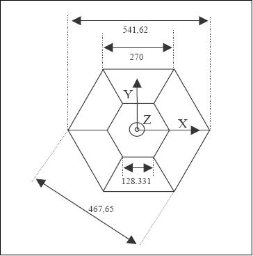
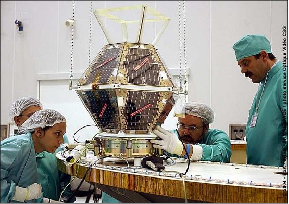
The satellite is spin-stabilized. The S/C structure consists of two hemispheres (top and bottom), each one has one hexagonal and six trapezoidal shaped sides. The overall structure approximates roughly a sphere. The satellite has the following subsystems: PDU (Power Distribution Unit), OBDH (On-Board Data Handling), RF communications, and experiments.
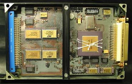
Power (17 W average) is provided by surface-mounted GaAs/Ge solar cells. Li-ion batteries provide 4.8 Ah of energy for eclipse operations. The OBDH provides all spacecraft control, processing functions and experiment interfacing (based on Motorola's microprocessor MC68332, 4 MB of storage capacity, 8 kB PROM, 512 kB EEPROM, 768 kB of protected RAM).
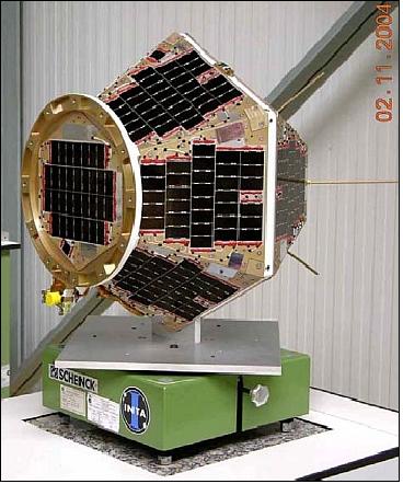
The two hemispheres of the S/C structure can be opened to permit easy access to all subsystems. Most of the equipment is attached to the central hexagon bus. The solar cells are glued to the 14 aluminum panels which are also part of the structure. A precise satellite pointing is not required (3-5º is sufficient). The ACS (Attitude Control Subsystem) employs solar cells and a magnetometer assembly for attitude sensing (description below under sensor complement).
The satellite mass is about 19 kg (actually a microsatellite by conventional definition), the S/C design life is 3 years.
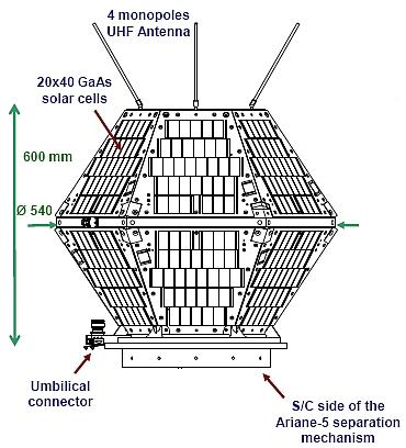
RF communications: The communications subsystem employs 4 omnidirectional antennas. Two digital modems are implemented for experimentation purposes; one uses a single DSP chip, the other is based on an ASIC design. The UHF band (387.1 MHz downlink, 400 MHz uplink, GMSK modulation and Viterbi encoding) is used for all data communications with the ground segment (store-and-forward approach). The downlink data rate is 24 kbit/s. All ground station access is based on the TDMA protocol using a Slotted Aloha access version. The onboard software design permits code updates to implement new functionalities. The mission control center for NanoSat-1 is located at the INTA facilities in Torrejon.
Launch
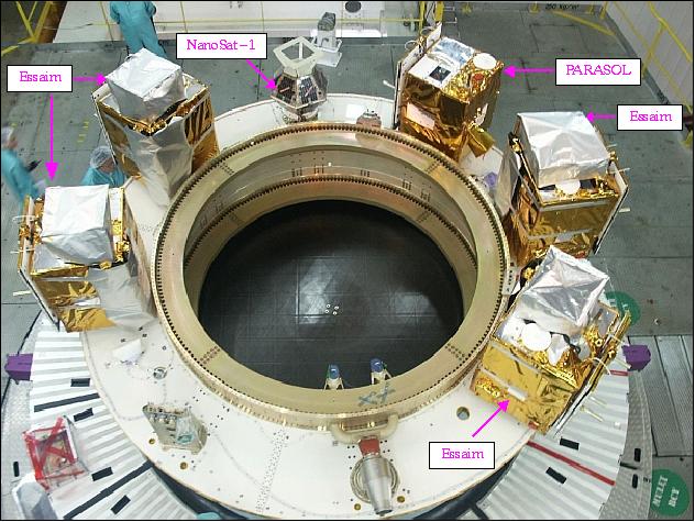
A launch of NanoSat-1 took place on Dec. 18, 2004 on an Ariane-5 vehicle (as an ASAP launch) from Kourou. The multiple launch involved the following S/C: Helios-IIA of DGA, France (primary payload), PARASOL of CNES as secondary payload to Helios-IIA, 4 Essaim (”swarm”) microsatellites of DGA, and the NanoSat-1.
Orbit: Sun-synchronous orbit, mean altitude = 661 km, inclination = 98.2º, period = 98 minutes, LTAN (Local Time on Ascending Node) at 13:00 hours.
Mission Status
• In 2012, Nanosat-01 and OWLS are still fully operative, and there is no evidence at all that make the project team think it will fail soon. 7)
• NanoSat-1 and OWLS (Optical Wireless Links for intra-Satellite) are operating nominally in 2010 (more than five years in orbit). All indications point in the direction of 1-2 more years of operations. 7)
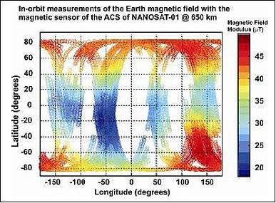
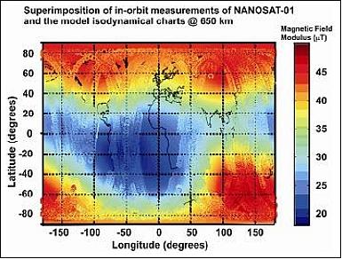
Also, the AMR sensor of the ACS is validated and functioning properly to measure the magnetic field vector in LEO, with a resolution of better than 0.1 mG.
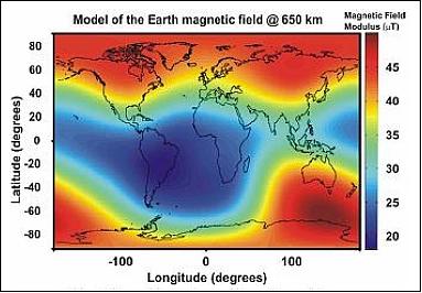
The AMR measurements over a period of 5 years are illustrated in Figure 7; the magnetic field model IGRF-10 is extrapolated for the satellite altitude of 650 km (Figure 8); Figure 9 shows the good match of the sensor with the magnetic field map provided by the model with a maximum mismatch in the order of the mG (Ref.9).
Sensor Complement
ACS (Attitude Control Subsystem)
The ACS, apart from being an in-orbit experiment for validating a magnetic COTS device, is also a part of the ACS of the spacecraft. For NanoSat-1, there are no pointing requirements (the solar cells are body-mounted on the quasi-sphere structure, antennas are omnidirectional, and no subsystem requires any pointing). Hence, the ACS of NanoSat-1 is based on four magnetic sensors and two solar sensors as sensing elements and three magneto-coils as actuators. The four magnetometers are required to measure the magnetic field within a precision of 10 nT. 8) 9)
The ACS design employs experimental magnetic sensors, designed and developed at INTA, to demonstrate in-orbit behavior of the system. Due to mass and volume restrictions, a miniaturized magnetometer assembly (other than the conventional fluxgate solution) was selected, referred to as AMR (Anisotropic Magnetic Resistor). The AMR technology is an adequate choice for medium- to high-sensitivity (~ 3 mV/V/G) and resolution (~ 3 µG) requirements. AMR devices are a mature technology for magnetic field sensing. Among a great quantity of applications, these sensors cover the range of the Earth’s magnetic field (0.1 mT - 1 nT), which makes them a good choice for navigation. The objective is to validate the AMR technology for commercial devices in spaceborne applications.
The AMR magnetometer COTS (Commercial-off-the-Shelf) implementation consists of 4 Honeywell sensors (HMC1201) in cubic configuration. The objective is the measurement of the Earth's magnetic field (magnitude and direction). The magnetic field measurements have a resolution of 1 mGauss (mG) scalar in the range of ±0.1 Gauss. The instrument has a total mass of 0.220 kg (200 g control electronics) and a power consumption of < 2 W.
In nominal mode, the spin axis is perpendicular to the orbital plane and positive in the anti-clockwise direction. The operational spin rate is in the range of 3-6 rpm. The requirements call for non-continuous actuation (once a week for 10 minutes) of the spacecraft. The low actuation cycle frequency was selected to obtain a long operational life. 10)
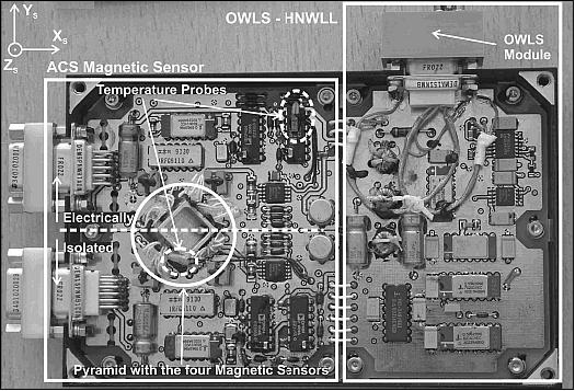
The entire ACS consists of a magnetic sensor, six solar cells, and three magnetotorquers. The magnetic sensor is composed by two biaxial sensors with two redundant PCBs (Printed Circuit Boards) of radiation-hardened proximity electronics, which conditions the sensor output signal, measure the temperature, and resets the AMR.
The technology used for the sensor is Anisotropic MagnetoResistance (AMR). The sensor is a COTS (Commercial Off-The-Shelf) product upscreened and fully tested for its use in space (Figure 10, Ref. 8).
Earth Magnetic Nanosensor
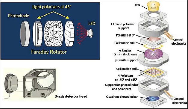
A Sol-Gel magneto-optical sensor was designed and developed to measure the gravitational parameters of the Earth and allow the orientation of the Nanosat-1. The heart of the magneto-optical device is a Sol–Gel prepared Faraday rotor, consisting of a dispersion of γ-Fe2 O3 nanoparticles in an amorphous silica matrix. 11)
When light propagates along the axis of a transparent rod, the application of an axial magnetic field to the rod causes a rotation of the plane of polarization of the light, due to the interactions between the light and the magnetic field (Figure 11).
β = V x B x d
where β is the angle of rotation, B is the magnetic flux density in the direction of propagation, d is the length of the path where the light and magnetic field interact, and V is the Verdet constant for the material. This empirical proportionality constant varies with wavelength and temperature.
In order to obtain an effective magneto-optical performance, the γ-Fe2 O3 nanocomposite material should comply with the following requirements:
- Superparamagnetic nanoparticles (particle size < 15 nm), to avoid remnant magnetization of the particles
- High transparency, to allow measuring the rotation of the light polarization plane
- High Verdet constant, to obtain a measurable rotation
- Good mechanical properties, to allow its integration in a magneto-optical device.

Magneto-optical device: In order to work as a sensor for magnetic fields, the nanocomposite should be stacked between a single polarizer and a set of four polarizers with their axis oriented at ±45º with respect to the first one, forming a polarimetric detection scheme (Figure 12). The light beam emitted by a LED is polarized, and its polarization plane rotated by the magnetic nanocomposite. This rotation is detected as an optical intensity change, thanks to the stack formed by the four polarizers and the array of four detectors (quadrant photodiodes).
The magneto-optical device has approximately 20 mm of diameter and less than 5 mm of thickness. It contains several coils for the sensor self-calibration (in order to compensate the possible drifts of the Verdet constant due to temperature or wavelength changes). The sensor head is composed of three magneto-optical devices to measure the magnetic field in the three spatial coordinates. The control electronics include a stabilized current source for the LED and a phase detection stage for the signal. According to the mission specifications, the nanosensor has a low mass (about 20 g for the sensor head and about 200 g for the control electronics) and a low power consumption (< 2 W).
The Sol–Gel-derived magneto-optic nanocomposite, consisting of a dispersion of magnetic nanoparticles in a silica matrix, was successfully implemented in a magnetic nanosensor based on the Faraday effect. The nanosensor is currently responsible for the orientation of the NanoSat-1 spacecraft with respect to Earth.
This important achievement is the result of a close and fruitful joint research venture, of 7 years between the National Institute for Aerospace Technology and the Materials Science Institute of Madrid. Is is anticipated, that the first Sol–Gel based technological development, now in-orbit, will open new possibilities to apply the enormous potential of the Sol–Gel technology to the design of new materials for challenging space applications aiming to the miniaturization of the satellites.
Solar Sensors
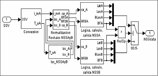
Two groups of sun sensors (Si cells and miniature AsGa/Ge cells) are used with the objective to: a) test the performance, and b) provide a means of sun aspect angle sensing for spin control. Since the output signal of each solar detector is proportional to the cosine angle of incidence of the solar radiation, the S/C spin axis determination is made by using the output from three out of six solar sensors positioned at known locations of the outer S/C surface. This method permits a nutation angle determination to within 5º.
Both groups of cells cannot be operated simultaneously since they use the same computer I/O channels. The conditioning electronics select the appropriate group of sensors and transform the temperature and current output (0-10 V range).
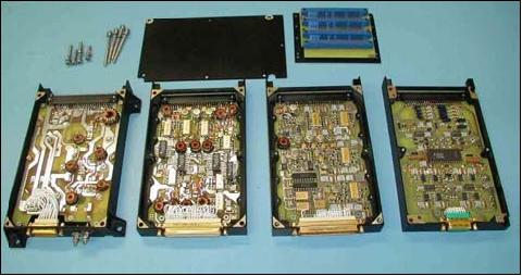
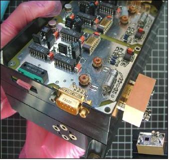
OWLS (Optical Wireless Links for intra-Satellite) Communications Experiment
The system, supported by ESA, is an intra-satellite diffuse infrared communications experiment for sensor data transmission and BER (Bit Error Rate) monitoring. The technologies are based on COTS (Commercial-off-the-Shelf) optoelectronics components. 12) 13) 14) 15) 16) 17)
The experimental setup features two OWLS communication demonstration experiments, representing the first ever OWLS spaceborne application.
The objective of OWLS was to serve a two-fold purpose: to perform an in-orbit demonstration of a wireless application, and characterize some aspects related to the behavior of OWLS in space.
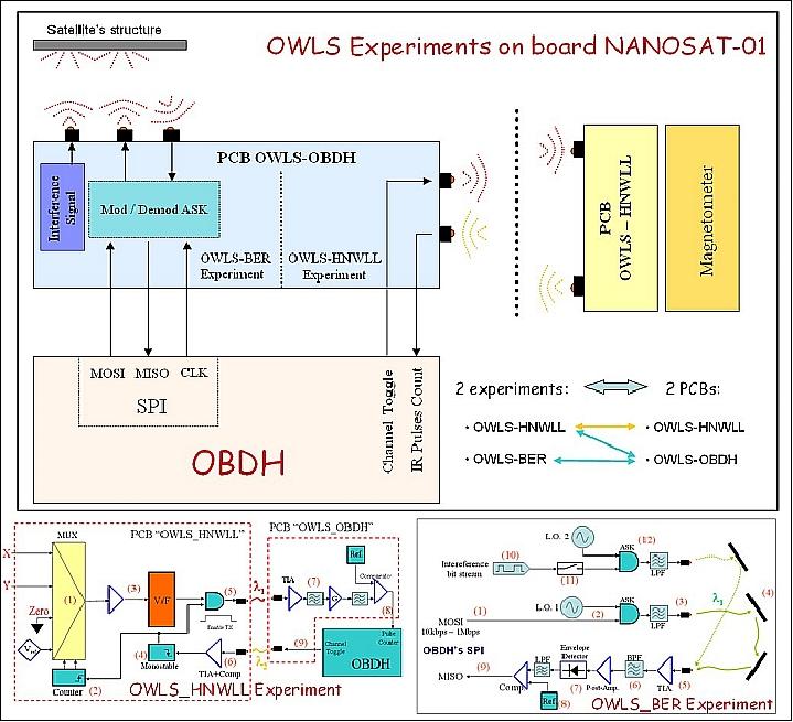
1) Magnetometer link, also referred to as OWLS-HNWLL (Honeywell): The first experiment is a redundant wireless link from a 3-axis magnetometer to the OBC. In parallel a wired connection exists, in such a way that data can then be compared. Besides its functional application, the intention was to measure the occurrence of SETs (Single Event Transients) in the optical detectors mainly due to incidence protons.
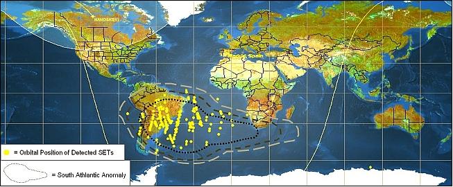
The experiment performs a V/F (Voltage-to-Frequency) conversion of the magnetic field measurement and transmits trains of optical pulses in fixed time-intervals, the number of pulses being proportional to the value of the signal. An additional channel was added, which theoretically sends zero pulses. Thus, all pulses are appearing when measuring that channel associated to particle incidences on the detector, the main source of errors of in-orbit optical links. The receiver offers a sensitivity of 700 nW/cm2 with a photodiode area of 25 mm2, and 1.5 MHz bandwidth. The emitter’s optical peak power is 15 mW. A WDMA (Wavelength Division Multiple Access) scheme is used for the wireless link. - The in-orbit data show that the only region, in which the effect of SETs is really important, is the South Atlantic Anomaly (SAA), as expected. There, the measured BER is in the order of 10-6. Figure 15 shows the location of transients detected during the year 2008. 18)
2) OWLS OBC link: The second OWLS experiment, also referred to as OWLS-BER, performs a closed-loop link in an SPI bus on the OBC. In this setup, data is sent from optical emitters towards the walls of the satellite, and the diffused light is collected by the receiver. Then the OBC performs a comparison of transmitted and received data to calculate BER. In this case, ASK is used with a 4 MHz subcarrier frequency. An interfering channel was added at a different frequency to test the FDMA (Frequency Division Multiple Access) capability. Both the on/off status of the interference and the data rate (from 100 kbit/s to 1 Mbit/s) can be commanded from ground.
The two OWLS demonstrations represent the first steps in an emerging technology for future fully wireless physical layer implementations, eventually with a large number of nodes based on optical technologies. The main advantages of onboard wireless communications are seen in: a) the saving of weight (since no wiring and connectors are needed; but it implies that MEMS technology is needed to achieve the results), and b) easier handling of all AIT (Assembly, Integration and Test) service functions.
Some results of OWLS after 5 years of on-orbit operations
The experimental results of two OWLS (Optical Wireless intra-spacecraft data Link) experiments onboard NanoSat-1 are reported for the 5 year period 2005-2010 in the following reference. 19)
• One of the experiments (called OWLS_HNWLL) establishes an optical link between the ACS (Attitude Control System) magnetometer and the OBDH (On-Board Data Handling Unit) . The magnetometer is based on a COTS magnetic sensor manufactured by Honeywell.
• The second one, called OWLS_BER, performs a closed-loop link within the SPI (Serial Peripheral Interface) bus of the OBDH, allowing for the calculation of link-level BER (Bit Error Rate) by comparing the emitted and received bit streams. In both cases, diffuse links are employed.
There are two outstanding effects of the space radiation environment on this kind of optical links. On the one hand, the SETs (Single Event Transients) on the optical detectors, due to the incidence of particles (mainly protons), is known to be the main source of errors in optical links in space. On the other hand, DD (Displacement Damage) generates a cumulative degradation of both the efficiency of the IREDs (Infra-Red Emitting Diodes) being used, and the responsivity of the receivers’ photodiodes.
Both effects were measured on board NanoSat-1. The experiments have allowed to measure the SET rate that takes place in the optical receivers being used, which use indirect gap detectors and are more sensitive (-40 dBm, average optical power), have bigger detecting areas (25 mm2), and lower bandwidth than those employed in previous fiber optics works. The DD on the optoelectronic components and its final effect on the optical power budget of a digital link were also measured by means of an innovative technique. - Finally, those results were compared with estimates done through the characterization of the receiver cross-section (SET) and optoelectronics degradation (DD), obtained from proton irradiation tests.
- One of the experiments provided the first in-orbit measurements of the SETs rate for the kind of receivers employed in diffuse optical links (high-sensitivity, moderate bandwidth, large photodiodes, wide FOV). The worst case BER, in the center of the SAA, due to SET-induced pulses in the optical receivers, remains in the order of 10-6.
- The second experiment has proven that the degradation due to DD is negligible for the optoelectronic parts used in the experiments. Both kinds of in-orbit measurements were contrasted with data obtained from proton irradiation tests, and good results were obtained.
The measurement of the aforementioned effects, specially the BER degradation due to SETs, was identified as a necessary step before optical wireless technology could be considered as a platform technology to be used on board a spacecraft. Previous work had never dealt with the kinds of receivers required by OWLS, and the SET rate was expected to be considerable. The results have shown that this rate, even on the SAA, can be tolerated if a minimum error detection and/or correction capability is added. For non-critical applications, a simple parity bit may be enough. For critical applications, more advanced error correction techniques are suggested.
In 2012, the project team intends to focus its attention on the study of the SET rate over the Polar Regions to improve the statistics presented for these areas, and to study the effects of possible solar events.
It has also been shown, that the effect of DD can be negligible if a careful selection of the optoelectronic components is carried out. Optoelectronic COTS devices offering the best efficiency in terms of power are needed for OWLS. Ground tests, as those that led to the selection of the components used on board Nanosat-1, are required to ensure the minimum degradation of the emitter efficiency and detector responsivity.
As a continuation to this work, INTA will launch a nanosatellite named OPTOS (Optical Nanosatellite) that makes use of an optical wireless CAN bus. Its CRC (Cyclic Redundancy Code) guarantees a maximum rate of non-detected erroneous frames equal to 4.7 x 10⁻¹¹. If an error is detected, the whole frame is repeated. For the longest CAN frames (104 bits), a BER in the order of 10-6 only entails one repetition out of 104 frames, which is a negligible overhead, the final error rate is virtually 0 thanks to the aforementioned CRC. This is a clear example of a robust application of the OWLS technology (Ref. 19).
References
1) A. Martinez, I. Arruego, M. T. Alvarez, J. Barbero, et al., “Nanosatellites Technology Demonstration,” Proceedings of the 14th Annual AIAA/USU Conference on Small Satellites, Logan, UT, Aug. 21-24, 2000, SSC00-II-2
2) J. Torres, I. Tato, “Then and Now: From INTASat to Mini and Nanosatellites,” Proceedings of the 57th IAC/IAF/IAA (International Astronautical Congress), Valencia, Spain, Oct. 2-6, 2006, IAC-06-E4.4.06
3) http://www.inta.es/programasAltaTecnologia/nanosatelites.asp
4) “NanoSat 01 (in Spanish),” URL: http://www.inta.es/doc/programasaltatecnologia/nanosatelites/nanosat_1.pdf
5) I. Arruego, J. Martínez, S. Rodríguez, H. Guerrero, “Optical Wireless Techniques Demonstration On Board Nanosat-01,” ESA Workshop on 'Optical Wireless Onboard Communications,' ESA/ESTEC, Noordwijk, The Netherlands, Sept. 29-30, 2004
6) D. Guzman,M. Angulo, L. Seoane, S. Sanchez, M. Pietro, D. Meziat, “Overview of the INTASAT's Data Architecture Based on SpaceWire,” International SpaceWire Conference, Dundee, Scotland, Sept. 17-19, 2007, URL:. http://spacewire.computing.dundee.ac.uk/proceedings/Presentations/Missions and Applications 1/guzman.pdf
7) Information provided by Ignacio Arruego Rodriguez of INTA, Madrid, Spain
8) Marina Diaz-Michelena, Ignacio Arruego, Javier. Martinez Oter, Hector Guerrero, “COTS-Based Wireless Magnetic Sensor for Small Satellites,” IEEE Transactions on Aerospace and Electronic Systems, Vol. 46, No 2, April 2010, pp. 542-557
9) M. D. Michelena, M. F. Cerdán, I. Arruego, “NANOSAT-01: Three Years of Mission. Magnetic Scientific Results, Sensors Letters 7,” June 3, 2009
10) P. de Vicente y Cuena, M. A. Jerez, “Attitude Control System for NanoSat-1,” Proceedings of the 57th IAC/IAF/IAA (International Astronautical Congress), Valencia, Spain, Oct. 2-6, 2006, IAC-06-B5.6.16
11) M. Zayat, R. Pardo, G. Rosa, R. P. del Real, M. Diaz-Michelena, I. Arruego, H. Guerrero, D. Levy, “A Sol–Gel based magneto-optical device for the NANOSAT space mission,” Journal of Sol-Gel Science and Technology, Vol. 50, 2009, pp. 254-259, DOI 10.1007/s10971-009-1953-y
12) Hector Guerrero, Ignacio Arruego, Santiago Rodriguez, Maite Alvarez, Juan. J. Jimenez, Jose Torres, Patrice Pelissou, Claude Carron, Inmaculada Hernandez, Patrick Plancke, “Optical Wireless Intra-Spacecraft Communications,” Proceedings of the 6th International Conference on Space Optics (ICSO), ESA/ESTEC, Noordwijk, The Netherlands, June 27-30, 2006, (ESA SP-621, June 2006)
13) I. Arruego, M. D. Michelena, S. Rodríguez, H. Guerrero, “In-Orbit experiment of Intra-Satellite Optical Wireless Links On Board NanoSat-01,” Wireless Data Communications Onboard Spacecraft- Technology and Applications Workshop,” April 14-16, 2003, ESA/ESTEC, Noordwijk, The Netherlands
14) I. Arruego, J. Martínez, H. Guerrero, “First Data From Nanosat-01 OWLS experiments,” Proceedings of `Wireless for Space Applications Workshop,' ESA/ESTEC, Noordwijk, NL, July 10-13, 2006
15) “Validation of an optical physical layer for on board data communications in an optical context,” URL: http://esamultimedia.esa.int/docs/gsp/completed/C16428ExS.pdf
16) Santiago Rodriguez, Ignacio Arruego, Nikos Karafolas, Patrice Pelisou, Francisco Tortosa, Bernard Alison, Maite Alvarez, Victor Apestigue, Joaquin Azcue, Juan Barbero, Claude Carron, Jordi Catalan, Jose Ramon De Mingo, Jose Angel Dominguez, Paloma Gallego, Juan Garcia-Prieto, Juan Jose Jimenez, Demetrio Lopez, Francisco Lopez-Hernandez, Alberto Martin-Ortega, Javier Martinez-Oter, Gerald Mercadier, Francisco Peran, Ayaya Perera, Rafael Perz, Enrique Poves, Jose Rabadan, Manuel Reina, Joaquin Rivas, Helene Rouault, Julio Rufo, Claudia Ruiz de Galaterra, Denis Scheidel, Christophe Theroude, Marco van Uffelen, Jaime Sanchez-Paramo, Errico Armandillo, Patrick Plancke, Hector Guerrero, “Optical Wireless Intra-Spacecraft Communications,” Proceedings of the 7th ICSO (International Conference on Space Optics) 2008, Toulouse, France, Oct. 14-17, 2008
17) I. Arruego, H. Guerrero, S. Rodr¿guez, J. Mart¿nez-Oter, J. J. Jimenez, J. A. Dominguez, A. Martin-Ortega, J. R. de Mingo, J. Rivas, V. Apestigue, J. Sanchez, J. Iglesias, M. T. Alvarez, P. Gallego, J. Azcue, C. Ruiz de Galarreta, B. Martin, A. A lvarez-Herrero, M. Diaz-Michelena, I. Martin, F. R. Tamayo, M. Reina, M. J. Gutierrez, L. Sabau, J. Torres, “OWLS: A Ten-Year History in Optical Wireless Links for Intra-Satellite Communications,” IEEE Journal on Selected Areas in Communications, Vol. 27, No 9, Dec. 2009, pp. 1599-1611
18) “Optical Wireless for intra-Spacecraft Communications,” CCSDS Fall Meeting – Wireless Working Group, Berlin, Germany, October 14, 2008, URL: http://cwe.ccsds.org/sois/docs/SOIS-WIR/Meeting%20Materials/2008/Fall/CCSDS%20-%20BERLIN%202008%20-%20Optical%20Wire
less%20for%20intra%20Spacecraft%20Communications.pdf
19) Ignacio Arruego, Javier Martínez, Héctor Guerrero, “In-Orbit Measurement of SET and DD Effects on Optical Wireless Links for Intra-Satellite Data Transmission,” IEEE Transactions on Nuclear Science, Vol. 58, No 6, Dec. 12, 2011, pp. 3067-3075
The information compiled and edited in this article was provided by Herbert J. Kramer from his documentation of: ”Observation of the Earth and Its Environment: Survey of Missions and Sensors” (Springer Verlag) as well as many other sources after the publication of the 4th edition in 2002. - Comments and corrections to this article are always welcome for further updates (eoportal@symbios.space).