OICETS (Optical Interorbit Communications Engineering Test Satellite)
Non-EO
JAXA
Technology and Research
Quick facts
Overview
| Mission type | Non-EO |
| Agency | JAXA |
| Launch date | 23 Aug 2005 |
| End of life date | 24 Sep 2009 |
OICETS (Optical Interorbit Communications Engineering Test Satellite) / Kirari
Spacecraft Launch Mission Status Sensor Complement References
OICETS (also referred to as Kirari, meaning "glitter" or "twinkle" in Japanese) is a JAXA (Japan Aerospace Exploration Agency) technology satellite mission with the objective to conduct, with ESA cooperation, on-orbit demonstrations of high-accuracy pointing, acquisition and tracking technologies (key elements of optical interorbit communications), important for future space activities such as global data reception from Earth observation satellites. The OICETS mission goal is to conduct interorbit laser communications experiments with ARTEMIS of ESA. The advantages of optical communications are seen in the support of much higher data rates and transmission capacities than in conventional radio links, lower risk of link interference with other optical communication systems (there can be no interference between optical and radio transmissions), as well as in more compact and lighter designs of communication equipment. The program was begun in 1993 when JAXA (formerly NASDA) and the ESA signed an agreement regarding cooperation in optical communications in space.
Background: JAXA began the development of the OICETS in 1995 and the detailed technological coordination with ESA. Although international technological coordination was difficult, JAXA learned a lot from Europe which had advanced experience. The ARTEMIS was launched in July 2001 but it turned out that the deployment of the geostationary satellite to orbit was significantly delayed due to trouble with the launch vehicle. Since it was necessary to see whether the ARTEMIS could be made geostationary, the Space Activities Commission decided in August 2001 to postpone the launch of the OICETS. 1)
However it turned out that, after ESA worked hard, the ARTEMIS was able to be put into the geostationary orbit in the beginning of 2003. Then, JAXA made a proposal to the Space Activities Commission for launching the OICETS in 2005, considering the fact that the optical communication device in the ARTEMIS would end its design life in 5 years (in July 2006). The Commission checked if the initial significance and purpose were still maintained in the project and discussed the validity of the project including the launch vehicle. As a result it was appreciated once again that the initial significance of the demonstration of optical inter-orbit communications in space was still valid, that early demonstrations of optical communications in space were still important for future technologies of Japan, and that the techniques could be applied to high precision ranging and other technologies. On the other hand, the discussion on the launch vehicle was continued in order to select the most appropriate launch method with an aim to launching the OICETS in 2005.
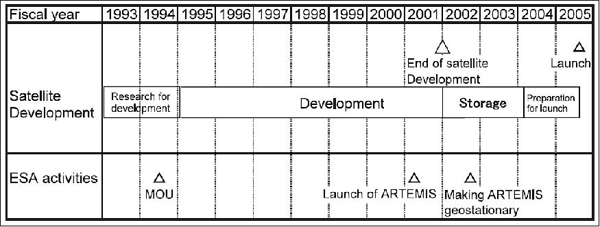
Through the discussions on the selection of the launch vehicle, it was found that the first stage of the J-I rocket could not be used due to an accident with the H-IIA rocket No. 6, and the H-IIA rocket could not be used as it was to be used to launch another satellite, M-V rocket could not be used due to a launch environment problem, and the GX rocket could not be used as it was still under development. In this difficult situation, the possibility of using a foreign rocket was examined as the second best way. In these discussions, the actual flight record and reliability of the rocket launching, the compatibility of the schedule, and delivery problems of the satellite were taken into account. As a consequence, a plan for launching the satellite with the Russia-Ukraine Dnepr rocket from the Baikonur Cosmodrome in 2005 was proposed in December 2004 to the Space Activities Commission, which then approved the proposal. Figure 1 shows the development schedule of the OICETS from the start of development to the launch.
Demonstration experiment in orbit: Compared to radio wave communication systems, optical communication systems have the following advantages:
1) High antenna gain increases data transmission rate, reduces transmission power, and softens requirements for receivers.
2) The size, mass and power consumption of communication devices can be reduced.
3) The attitude is highly stable due to low attitude disturbances from the operation of small optical antenna.
4) EMI (Electromagnetic Interference) can be reduced.
5) The systems are highly resistant to interference and interception of communications and advantageous in terms of communication confidentiality.
Figure 2 compares actual radio wave communications satellites and optical inter-orbit communications satellites. To take advantage of optical inter-orbit communications, there are some technical problems to be solved. The maximum distance between a geostationary satellite and a low earth orbit satellite is 40,000 km. For satellites that are far away from each other to transmit and receive laser beams to a precision of several micro radians, high-precision optical devices and technology for their accurate control are necessary. The project demonstrated with the OICETS the key element technologies, checked performance degradation in the space environment, and obtained data for practical use.
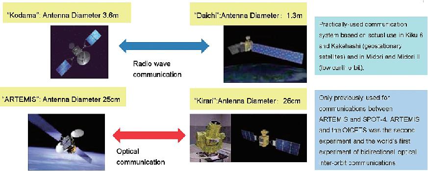
The major items of the in-orbit experiments are:
• Fine tracking and pointing experiments — bidirectional optical inter-orbit communications are performed and their major key element technologies are demonstrated.
• Optical inter-orbit communications experiments — optical inter-orbit communications experiments are performed many times to obtain statistical data for practical use.
• Evaluation experiments for optical devices — degradation characteristics of major optical devices are examined in space environment.
• Satellite micro vibration measurement experiments — micro vibration of the satellite is measured to evaluate its influence on optical inter-orbit communications.
• Optical ground station experiments (additional experiments after launch) — experiments of optical communications between the OICETS and ground stations are conducted.
Spacecraft
The OICETS satellite is three-axis stabilized with a box-shaped bus (of dimensions 0.78 m x 1.1 m x 1.5 m in height) and two solar panels (the S/C has a span of 9.4 m with both panels deployed). The spacecraft was built by NEC of Tokyo. The spacecraft power is 1220 W (EOL), NiMH batteries of 13 Ah provide power during the eclipse phase of the orbit. S/C mass = 570 kg, the mission life time of about one year. 2) 3)
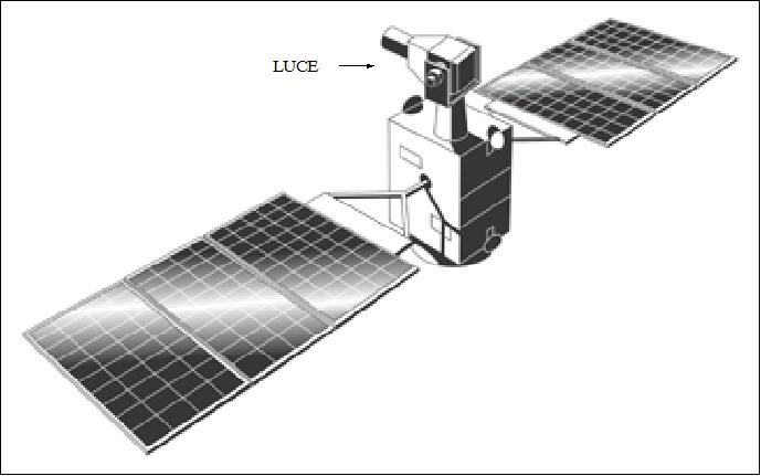
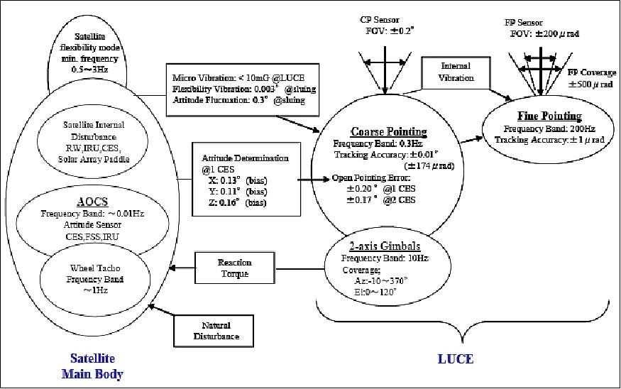
The attitude and orbit control subsystem (AOCS) consists of reaction wheels and magneto-rods for actuation, gyros, fine and coarse accuracy sun sensors, and Earth horizon sensors provide the attitude sensing. The attitude determination accuracy is specified within 0.2º (3σ). AOCS maintains the attitude of OICETS within specified limits, caused by LUCE movements/perturbations, by exchanging some data with LUCE. The pointing for interorbit communication is done at the LUCE level. 4)
Spacecraft mass, power | 570 kg, > 1200 W @ EOL |
Spacecraft size | 1.1 m (width) x 2.64 m (height) x 9.4 m (length of solar array x 1.75 m wide) |
AOCS (Attitude and Orbit Control Subsystem) | Three-axis stabilized, zero momentum type |
Pointing accuracy | Roll / pitch:±0.130º (3σ); yaw:±0.162º (3σ) |
Solar array paddle / solar cell | Rigid / high-efficiency silicon |
Battery | 13Ah, Nickel-Metal Hydride (NiMH) x 2 |
Antenna | Optical inter-orbit link: center-feed Cassegrain (26 cm) |
Propulsion | 1 N thruster assembly (N2H4 monopropellant) x 4 x 2 (redundant) |
Design life | 1 year |
Launch
The launch of OICETS on a Dnepr vehicle took place on Aug. 23, 2005 (UTC) from the Baikonur Cosmodrome, Kazakhstan. The secondary payload on this flight was INDEX (Innovative Technology Demonstration Experiment) of JAXA. 5)
Orbit: Sun-synchronous circular orbit, altitude = 610 km (BOL) to 550 km (EOL), inclination = 97.8º, period = 95 minutes.
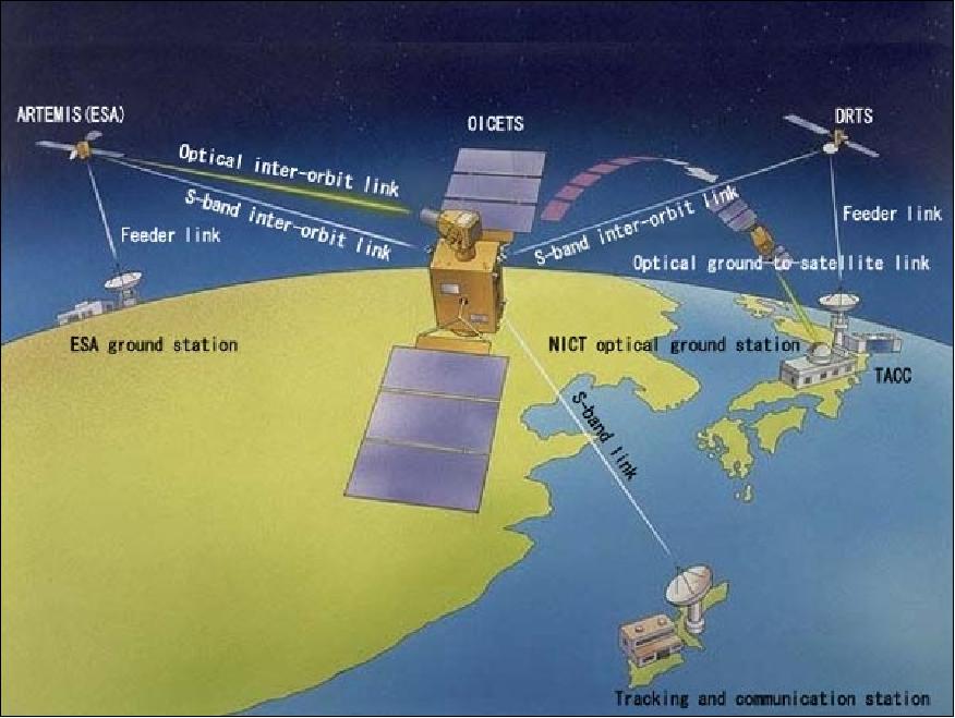
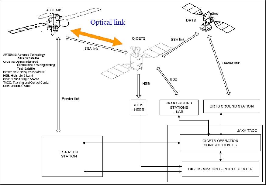
Communication links: OICETS has 2-way communication links, which are the S-band interorbit link with the data relay satellites (ARTEMIS and DRTS), and a USB (Unified S-band) link with the ground station for telemetry and command operation services. In order to downlink a large volume of mission data to the ground station, the HSB (High speed S-band) downlink, BPSK modulated, is used (see Table 4).
Mission Status
• On September 24, 2009, the OICETS/Kirari spacecraft was retired for the second time. The OICETS mission is regarded an extraordinary success by all parties involved. 6) 7)
• The Phase-4 laser communications experiment series was conducted from October 2008 to February 2009. The laser beam propagation characteristics were measured and new fast-steering mirrors were tested to couple the downlink laser beam into the single-mode optical fiber. Low-density parity check (LDPC) codes were designed for the ground-to-OICETS laser communications links and tested. The polarization characteristics of an artificial laser source in space, such as Stokes parameters, and the degree of polarization were measured through space-to-ground atmospheric transmission paths. 8)
International laser communications experiments were then successfully conducted with four optical ground stations located at NASA/JPL (Jet Propulsion Laboratory), Pasadena, CA, the ESA OGS (Optical Ground Station) on Mount Teide, Tenerife, Spain, the DLR/IKN (German Aerospace Center/Institute of Communications and Navigation) optical ground station in Germany, and NICT in Japan as the Phase-5 experiment. The purpose of the Phase-5 experiment was to establish OICETS-to-ground laser communication links from the different optical ground stations (Ref. 8). 9) 10) 11) 12)
The results of Phase-4 and -5 contribute to the link estimation for QKD (Quantum Key Distribution) via space and provide the potential for enhancements in quantum cryptography on a global scale in the future.
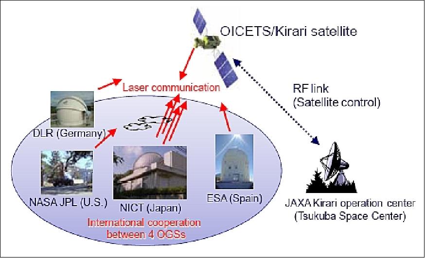
• NICT reactivated the OICETS satellite in October 2008 to support bi-directional high bandwidth optical link (2 Mbit/s uplink and 50 Mbit/s downlink). 13)
- The OCTL (Optical Communications Telescope Laboratory) to OTOOLE (OCTL to OICETS Optical Link Experiment) is a joint NASA/JPL and JAXA, NICT bi-directional link experiment. The OCTL is located in the San Gabriel Mountains of Southern California. The OCTL houses a 1 m elevation/azimuth coudé-mount telescope co-aligned with a 20 cm acquisition telescope. The telescope tracks orbiting satellites as low as 250 km and slews at a maximum rate of 20º/s in azimuth and 10º/s in elevation, and can readily track the 601 km altitude OICETS satellite (Ref. 13). 14)
- In late 2006, JAXA dismantled the TT&C ground terminals for laser communication experiments. This resulted in the fact that only the HK (Housekeeping) telemetry data of the OICETS satellite bus could be monitored without any laser communication experiment availability. However, in the timeframe April 2007 - Sept. 2008, NICT rebuilt the ground mission control system, permitting the support of further optical experiments with OICETS. 15)
• On Oct. 16, 2006, the mission operations of the "Kirari (OICETS)" spacecraft were terminated after successful technology experiments had been conducted with a GEO satellite (ARTEMIS) and several optical ground stations. 16)
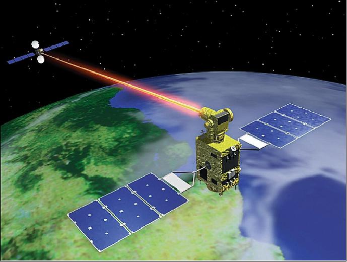
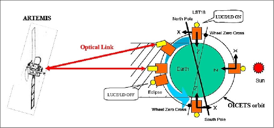
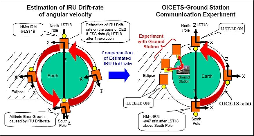
- The first bi-directional optical link (data and command transmission) between OICETS/Kirari and ESA's ARTEMIS spacecraft (LEO-GEO) was made on Dec. 9, 2005. This represented the world's first bidirectional optical interorbit communication (Figure 7). - To perform this experiment, the Z axis of the OICETS satellite is controlled by using CES (Conical Earth Sensor), FSS (Fine Sun Sensor), and the IRU (Inertial Reference Unit) of the AOCS to turn the satellite toward the Earth. 17) 18)
• Later on, this was followed by many more acquisitions (over 100). Most of interorbit links were achieved without any failure during experiments.
• On June 7, 2006, an optical communication experiment was conducted between OICETS and the optical ground station "OGS-OP" (Optical Ground Station Oberpfaffenhofen) of the German Aerospace Center (DLR). 19)
• JAXA/NICT carried out optical communication experiments between March 22-31, 2006 using laser beams between OICETS and the optical ground station, referred to as KODEN (Kirari Optical communication Demonstration Experiments with the NICT optical ground station), in Koganei, Tokyo. The experiments were successfully performed on March 31 (LEO-ground station), referred to as Phase-1, in May 2006 (Phase-2), as well as in Sept. 2006 (Phase-3). These were the first ground-to-LEO laser communication experiments. - This required a highly sophisticated pointing technology because the satellite had to keep sending laser beams accurately to the ground station while moving at orbital speed (Figure 8). 20)
The ground station used a multibeam laser transmission system for the uplink. A 1.5 m telescope is used for uplink transmission, and a 20 cm telescope is used for downlink reception. Although the onboard optical terminal was designed for GEO-to-LEO links, its performance was sufficient for a direct link to the ground. Acquisition and tracking were successful when clear sky conditions prevailed. Optical links could thus be established even when there was atmospheric turbulence above the ground station. The uplink fluctuation was reduced by using a multi-beam laser transmission technique. The uplink communication quality can be further improved by using fading countermeasures, and downlink communication quality can be improved by using forward error coding.
• December 9, 2005: The first bi-directional optical link between KIRARI, the Japanese satellite officially called OICETS (Optical Inter-orbit Communications Engineering Test Satellite), and ESA's Artemis was made on Friday 9 December at 02:05 UTC. 21)
- Kirari is the second optical data relay satellite using Artemis, following the world premiere laser link with SPOT-4 in November 2001 in the framework of the SILEX development, an innovative payload which provides a laser beam as a data signal carrier. This optical service has operated regularly since then and accumulated more than 1100 links totalling 230 hours to date.
The Kirari experiment is the result of a long standing agreement between JAXA and ESA for cooperation on data relay services, and builds upon the SILEX development. - Kirari has, for the first time, used an optical link for both data and command transmission. The quality of the link was excellent.
Sensor Complement
LUCE (Laser Utilizing Communications Equipment)
LUCE is a JAXA-sponsored instrument built by NEC Toshiba Space Systems, Ltd. The main objectives of LUCE in-orbit experiments are: 22) 23) 24) 25) 26) 27)
- To evaluate the performance of optical devices in the space environment
- To evaluate the ATP (Acquisition Tracking and Pointing) capabilities of the system by using planets as targets
- To conduct interorbit communication experiments with ARTEMIS (including evaluation of atmospheric effects and micro-vibration effects caused by on-board equipment)
- To conduct optical communication experiments between OICETS and the CRL (Communication Research Laboratory) ground station.
Parameter | Forward link (ARTEMIS-OICETS) | Return link (OICETS-ARTEMIS) |
Wavelength | 819 nm (data) | 847 nm |
Polarization type | LHCP | LHCP |
Data rate | 2.048 Mbit/s | 49.3724 Mbit/s |
Signal format | 2 PPM (Pulse Position Modulation) | NRZ |
Required bit error rate | 10-6 | 10-6 |
The communication system of LUCE employs the IMDD (Intensity Modulation and Direct Detection) technique which switches the transmit laser source directly by the data stream OOK (On-Off Keying). LUCE utilizes the semiconductor LD (Laser Diode) as a transmission device and the APD (Avalanche Photo Diode) as detection device. The forward link uses the 2PPM (2 Pulse Position Modulation) format at 2.048 Mbit/s, while the return link uses the NRZ format at 49.3724 Mbit/s.
The optical part of LUCE (LUCE-O) is installed on the anti-Earth panel, the electronics unit of LUCE (LUCE-E) is located inside the S/C. The LUCE power consumption is about 230 W during communications support services.
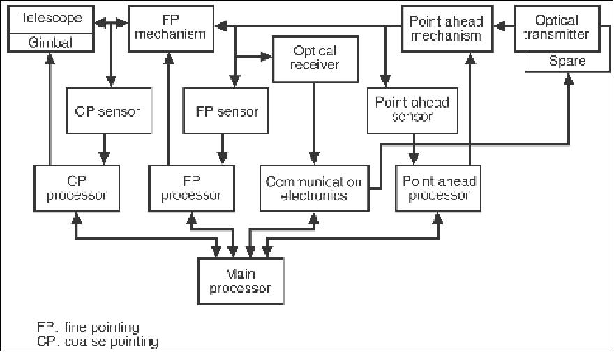
LUCE-O consists of three modules: an optical antenna, the optical system, and of two-axis gimbals. The optical antenna is a center-feed Cassegrain mirror telescope. The optical system, located behind the antenna and mounted on a thermally-controlled optical bench, consists of a laser transmitter, a receiver, ATP sensors and mechanisms, relay optics, and some electronics. The optical antenna and the optical system are mounted on two-axis gimbals, referred to as the "coarse pointing mechanism." The mass of LUCE-O is about 110 kg. LUCE-E includes the ATP control electronics and the communications electronics. The mass of LUCE is about 40 kg.
The ATP system performs the followings tasks:
- In the acquisition phase, ATP compensates for the initial LOS (Line of Sight) error, caused mainly by the host S/C (OICETS) attitude error and ephemeris error.
- In the tracking phase, ATP compensates dynamic disturbances caused by the host S/C and the terminal itself within a few micro-radians.
- In the pointing phase , ATP points the beam in the direction of the partner S/C and compensates for relative motion of the S/C during the finite travelling time of the communication beam.
ATP subsystem | Tracking accuracy | <±2 µrad (3σ) for acquisition |
Coarse acquisition and tracking components | Detector: CCD (672 x 488 pixels) | |
Fine acquisition and tracking components | Detector: QD (Quadrant Detector) | |
Receiving beam wavelength | Beacon: 797 to 808 nm | |
Transmission subsystem | Laser diode | Wavelength: 843 to 853 nm |
Receiver subsystem | Detector | APD (Avalanche Photo Diode) |
Optical antenna | Diameter | 26 cm (effective) |
MVE (Micro-Vibration Measurement Equipment) | Frequency range | 0.5 to 1000 Hz |
|
|
|
Items of pointing subsystems | Coarse-pointing mechanism | Fine-pointing mechanism |
Structure | 2-axis gimbals | Pair of independent 1-axis mirror drives |
Angular coverage | Azimuth: 10-370º | ±500 µrad |
Tracking accuracy | ±0.01º | ±1 µrad |
FOV (Field of View) | ±0.2º | ±200 µrad |
Bandwidth | 2 Hz | 200 Hz |
The ATP system supports the above functions by a coarse-pointing system, a fine-pointing system, and a point-ahead system. The coarse- and the fine-pointing systems perform the acquisition and tracking of the incoming beam - while the point-ahead system maintains the pointing direction. The coarse-pointing mechanism consists of the two-axis gimbals, two optical encoders, and two direct-drive motors. A CCD detector array (672 x 488) is used as the coarse-pointing sensor for initial acquisition and tracking of the incoming beam. The fine-pointing mechanism consists of two assemblies leading the incoming beam for x- and y-axis respectively. Angular errors of the incoming beam misalignments of ±1 µrad are detected in the tracking phase. The point-ahead mechanism uses the same design as the fine-pointing mechanism. Quadrant silicon photo diodes (QD) are used to sense misalignments.
In addition to LUCE, OICETS is carrying MVE (Micro-Vibration Measurement Equipment) to sense the vibration environment of the spacecraft.
OICETS Experiment Concept
The configuration of the overall system for optical interorbit communication experiments consists of the following space segment elements: OICETS in LEO, DRTS (Data Relay Test Satellite) of JAXA in GEO, ARTEMIS of ESA in GEO. The ground segment consists of JAXA's TACC (Tracking and Control Center) and domestic ground stations as well as of an ESA ground station at Redu, Belgium (experiments between OICETS and ARTEMIS). OICETS is controlled by TACC via an S-band interorbit link, or by an S-band direct link with TACC. The technical challenge of the technology of the optical experiment demonstration between LEO and GEO satellites involves alignment and stabilizing issues, it requires pointing errors of a few µrad by each S/C.
Link | Direction | Data and Data Rate |
HSB (High Speed S-band) downlink | OICETS → Ground station | MTM (Mission Telemetry) 1 Mbit/s |
USB (Unified S-band) uplink | OICETS ← Ground station | CMD (Command) 500 bit/s |
USB downlink | OICETS → Ground station | TLM (Telemetry) 500 bit/s (real-time) TLM 16 kbit/s (playback) |
DRTS SSA forward link | OICETS ← DRTS | CMD 125 bit/s |
DRTS SSA (S-band Single Access) return link | OICETS → DRTS | TLM 512 bit/s (real-time) |
ARTEMIS SSA forward link | OICETS ← ARTEMIS | CMD 125 bit/s |
ARTEMIS SSA return link | OICETS → ARTEMIS | TLM 512 bit/s (real-time) |
ARTEMIS optical forward link | OICETS ← ARTEMIS | PN code 2.048 Mbit/s |
ARTEMIS optical return link | OICETS → ARTEMIS | PN code 49.3724 Mbit/s |
Acquisition, tracking and pointing performance: In the experiments, ARTEMIS (GEO terminal) has a beacon beam, but OICETS (LEO terminal) does not. Therefore, the following acquisition procedures are needed. 28)
- Both terminals point to each other by applying open-loop control based on onboard orbital models
- ARTEMIS scans a general pointing region with the beacon beam whose divergence is much wider than its communication beam
- Upon reception and detection of the beacon beam from ARTEMIS, OICETS immediately transmits its communication beam toward ARTEMIS
- Upon reception and detection of the communication beam from OICETS, ARTEMIS stops scanning the beacon beam and transmits a communication beam to OICETS, followed by the turn-off of the beacon beam
- To initiate the interorbit link, each satellite continuously transmits the communication beam toward the other spacecraft to enable the partner satellite to improve its pointing accuracy.
Both mechanisms, coarse-pointing and fine-pointing, are working cooperatively fulfilling their roles for accurate tracking.
Communication performance: The optical return link from OICETS to ARTEMIS is modulated with an NRZ format whose data rate is 49.3724 Mbit/s. LUCE is capable of generating PN code and transmitting it to ARTEMIS. These data are downlinked to an ESA's ground station at Redu, Belgium, via a Ka-band radio frequency feeder link of ARTEMIS. The forward link form ARTEMIS to OICETS is modulated to a 2PPM format whose data rate is 2.048 Mbit/s. LUCE is equipped with a bit error counter to evaluate the link quality. The forward link data of the PN code is also transmitted from the Redu station via the Ka-band feeder link.
In all the experiments, the forward link bit error results measured by the LUCE terminal were zero (i.e., error free) at the ARTEMIS laser output power condition of 37.5 mW and 60 mW.
References
1) Katsuyoshi Arai, "Overview of the Optical Inter-orbit Communications Engineering Test Satellite (OICETS) Project," Journal of the National Institute of Information and Communications Technology Vol. 59 No 1/2, 2012, URL: http://www.nict.go.jp/publication/shuppan/kihou-journal/journalvol59-1_2/journal-vol59no1_2-02.pdf
2) OICETS brochure of JAXA, URL: http://global.jaxa.jp/activity/pr/brochure/files/sat09.pdf
3) Takashi Jono,"Changing communications in space with light," URL: http://global.jaxa.jp/article/interview/no18/index_e.html
4) Yasuhiro Morita, "About Optical Inter-orbit Communications Engineering Test Satellite "KIRARI"," JAXA, March 7, 2006, URL: http://global.jaxa.jp/projects/sat/oicets/
5) T. Yamawaki, N. Takahashi , K. Arai, I. Mase, K. Ikebe, J. Nakajima, "Launch of Kirari (OICETS) from Baikonur," Proceedings of 25th ISTS (International Symposium on Space Technology and Science) and 19th ISSFD (International Symposium on Space Flight Dynamics), Kanazawa, Japan, June 4-11, 2006 , paper: 2006-j-06
6) Information provided by Morio Toyoshima of NICT (National Institute of Information and Communications Technology), Koganei, Tokyo, Japan
7) T. Jono, "Development of Optical Inter-orbit Communications Engineering Test Satellite (OICETS)," International Workshop on Ground-to-OICETS Laser Communications Experiments 2010, (GOLCE 2010), May 13-15, 2010, Tenerife, Spain, paper: GOLCE2010-09
8) Morio Toyoshima, Hideki Takenaka, Yozo Shoji, Yoshhisa Takayama, Yoshisada Koyama, Hiroo Kunimori, " Results of Kirari optical communication demonstration experiments with the NICT optical ground station (KODEN) aiming for future classical and quantum communications in space," Proceedings of the 61st IAC (International Astronautical Congress), Prague, Czech Republic, Sept. 27-Oct. 1, 2010, IAC-10.B2.1.10
9) Keith E. Wilson, Joseph Kovalik, Abhijit Biswas, Malcolm Wright, William T. Roberts, Yoshihisa Takayama, Morio Toyoshima, Shiro Yamakawa, "Results
of the Optical Link between OCTL and OICETS," 61st IAC (International Astronautical Congress), Prague, Czech Republic, Sept. 27-Oct. 1, 2010, IAC-10.B2.1.9
10) Florian Moll, "KIODO (KIrari's Optical Downlink to Oberpfaffenhofen) 2009: Trials and Analysis," International Workshop on Ground-to-OICETS Laser Communications Experiments 2010, (GOLCE 2010), May 13-15, 2010, Tenerife, Spain, paper: GOLCE2010-14
11) Hideki Takenaka , Morio Toyoshima, "Study of fiber coupling efficiency for ground-to-satellite laser communication links using OICETS," International Workshop on Ground-to-OICETS Laser Communications Experiments 2010, (GOLCE 2010), May 13-15, 2010, Tenerife, Spain, paper: GOLCE2010-15
12) Bernhard Furch, Zoran Sodnik, Josep Perdigues, "ESA's Activities in Optical Communications and Quantum Entanglement," International Workshop on Ground-to-OICETS Laser Communications Experiments 2010, (GOLCE 2010), May 13-15, 2010, Tenerife, Spain, paper: GOLCE2010-03
13) Keith E. Wilson, "Preparations for Planned OCTL to OICETS Optical Link Experiment (OTOOLE)," IPN Progress Report 42-177, May 15, 2009, URL: http://ipnpr.jpl.nasa.gov/progress_report/42-177/177B.pdf
14) Keith E. Wilson, Joseph Kovalik, Abhijit Biswas, Malcom Wright, William T. Roberts, Yoshihisa Takayama, Shiro Yamakawa, "OCTL Planning, Tests and Operations for the bi-directional link to the OICETS," International Workshop on Ground-to-OICETS Laser Communications Experiments 2010, (GOLCE 2010), May 13-15, 2010, Tenerife, Spain, paper: GOLCE2010-10
15) Y. Takayama, M. Toyoshima, S. Yamakawa, N. Kura, "Rebuilding and Operations of Ground Functions for OICETS-OGS Experiments," International Workshop on Ground-to-OICETS Laser Communications Experiments 2010, (GOLCE 2010), May 13-15, 2010, Tenerife, Spain, paper: GOLCE2010-13
16) "Mission operation completed with 'extra success'," Nov. 2, 2006, URL: http://www.jaxa.jp/projects/sat/oicets/topics_e.html
17) Y. Fujiwara, M. Mokuno, T. Jono, T. Yamawaki, K. Arai, M. Toyoshima, H. Kunimori, Z. Sodnik, A. Bird, B. Demelenne, "Optical Interorbit Communications Engineering Test Satellite (OICETS)," Proceedings of the 57th IAC/IAF/IAA (International Astronautical Congress), Valencia, Spain, Oct. 2-6, 2006, IAC-06-B3.5.10
18) Y. Fujiwara, T. Jono, T. Yamawaki, K. Arai, M. Toyoshima, H. Kunimori, Z. Sodnik, A. Bird, B. Demelenne, "Optical inter-orbit communications engineering test satellite (OICETS)," Acta Astronautica, Vol. 61, Issues 1-6, June-August 2007, pp. 163-175
19) "Success with Optical Communication Experiment between the Optical Inter-orbit Communication Engineering Test Satellite "Kirari" (OICETS) and the Optical Ground Station at German Aerospace Center (DLR)," June 9, 2006, JAXA, URL: http://www.jaxa.jp/press/2006/06/20060609_kirari_e.html
20) M. Toyoshima, K. Takizawa, T. Kuri, W. Klaus, M. Toyoda, H. Kunimori, T. Jono, Y. Takayama, K. Arai, "Development of the Optical Ground Station for the OICETS Satellite and Experimental Results," Proceedings of the 57th IAC/IAF/IAA (International Astronautical Congress), Valencia, Spain, Oct. 2-6, 2006, IAC-06-B3.4.04
21) "Successful optical data relay link between OICETS and Artemis," ESA, Dec. 9, 2005, URL: http://m.esa.int/Our_Activities/Telecommunications_Integrated_Applications/
Successful_optical_data_relay_link_between_OICETS_and_Artemis
22) T. Yamawaki, T. Jono, M. Toyoshima, K. Nakagawa, A. Yamamoto, K. Shiratama, Y. Koyama, " Development of LUCE for OICETS," 51st IAF Congress, Rio de Janeiro, Brazil, Oct. 2-6, 2000, IAF-00-M.2.05
23) K. Nakagawa, A. Yamamoto, M. Toyoda, "Performance test result of LUCE engineering model," Photonics West, Free Space Laser Communications Technologies XII of SPIE, San Jose, CA, Jan. 22-26, 2000
24) http://www.esa.int/esaCP/SEMIJVVLWFE_index_0.html
25) Y. Fujiwara, T. Jono, T. Yamawaki, K. Arai, M. Toyoshima, H. Kunimori, Z. Sodnik, A. Bird, B. Demelenne, "Optical inter-orbit communications engineering test satellite (OICETS)," Acta Astronautica, Vol. 61, Issues 1-6, June-August 2007, pp. 163-175
26) Y. Fujiwara, M. Mokuno, T. Jono, T. Yamawaki, K. Arai, M. Toyoshima, H. Kunimori, Z. Sodnik, A. Bird, B. Demelenne, "Optical inter-orbit communications engineering test satellite (OICETS)," Proceedings of the 57th IAC/IAF/IAA (International Astronautical Congress), Valencia, Spain, Oct. 2-6, 2006, IAC-06-B3.5.10
27) S. Usuki, N. Nagao, T. Takami, H. Miyamoto, "The preparations for OICETS TT&C operation and results of Initial phase," Spaceops 2006, June 19-23, 2006, Rome, Italy
28) T. Jono, Y. Takayama, N. Kura, K. Ohinata, Y. Koyama, K. Shiratama, J. Abe, K. Arai, "Functional Demonstration of the Laser Utilizing Communication Equipment on OICETS," Proceedings of 25th ISTS (International Symposium on Space Technology and Science) and 19th ISSFD (International Symposium on Space Flight Dynamics), Kanazawa, Japan, June 4-11, 2006 , paper: 2006-j-07
The information compiled and edited in this article was provided by Herbert J. Kramer from his documentation of: "Observation of the Earth and Its Environment: Survey of Missions and Sensors" (Springer Verlag) as well as many other sources after the publication of the 4th edition in 2002. Comments and corrections to this article are always welcome for further updates (eoportal@symbios.space).
Spacecraft Launch Mission Status Sensor Complement References Back to Top