PIXL-1 / Formerly CubeL or OSIRIS4CubeSat
Non-EO
DLR
Operational (nominal)
Communications
Quick facts
Overview
| Mission type | Non-EO |
| Agency | DLR |
| Mission status | Operational (nominal) |
| Launch date | 24 Jan 2021 |
PIXL-1 / Formerly CubeL (Laser CubeSat) or OSIRIS4CubeSat (Optical Space Infrared Downlink System) CubeSat Mission
Payload Launch Mission Status Ground Segment References
PIXL-1 is a joint CubeSat mission of the Institute of Communications and Navigation at the German Aerospace Center DLR-IKN) and Tesat Spacecom of Backnan DLR-IKN and Tesat developed and manufactured in cooperation highly compact optical communication payloads for small spag, Germany, to test laser communications for CubeSats. Concisely, PIXL-1 is a technology demonstrator for the optical demonstration payload in the framework of the OSIRIS program. Within this project, thececraft. The commercialization of the optical payload will take place under the designation "CubeLCT". 1)
Space industry has undergone a significant change over the last years. The development moved from large and costly spacecrafts to cost-efficient designs and shorter development times. While the satellites became smaller, the resolution of high compact sensors increased which led to a high data-volume to be transmitted and increasing demands for higher data rates on small satellites. This motivated for a highly compact version of DLR's optical communication payload OSIRIS for small LEO satellites. 2)
Name explanation of the mission: DLR-IKN developed within the project "OSIRIS4CubeSat" (Optical Space Infrared Downlink System) 'the world's smallest laser terminal. 3)
• At DLR the laser terminal name is OSIRIS4CubeSat (OSIRIS for CubeSat) = project name
• Tesat, the industrial partner of DLR, sells the laser terminal under the name: CubeLCT (CubeSat Laser Communication Terminal)
• DLR named the 3U CubeSat for laser downlink communication: CubeL
• The name of the mission is PIXL-1.
The Payload - OSIRIS4CubeSat (Optical Space Infrared Downlink System)
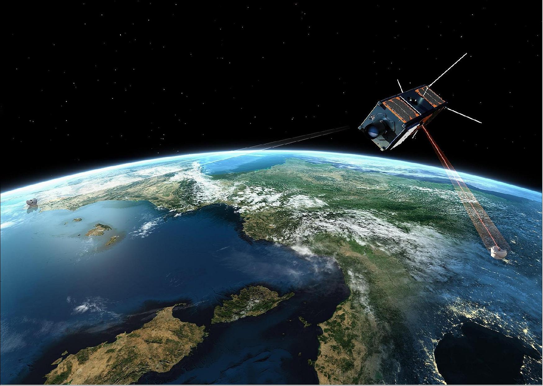
The objective of the OSIRIS4CubeSat project is to design and develop a very compact, power efficient laser terminal, motivated by the limitations in nano- and picosatellites for SWAP (Size Weight and Power). Its size of only 0.3 U CubeSat, as well as the mechanical standard of PC/104, allows the integration in most of the common CubeSat busses. The CubeLCT can transmit data up to 100 Mbit/s from Low Earth Orbit (LEO) to the ground, by consuming less than 8.5 W of electrical power. Preliminary link throughput estimations with a typical OGS (Optical Ground Station) network show, that with a data rate of 100 Mbit/s, an average volume of 4 GByte/day can be transmitted to ground, which equals hundreds of high resolution images.
The fundamental idea for the laser terminal is to use PCBs (Printed Circuit Boards) for the electronics system as the optical bench. Integrating the optical parts directly on the PCB allows maximum compactness. To avoid misalignments due to thermal deformation, a CIC (Copper-Invar-Copper) PCB was used.
To realize optical communication on a CubeSat, the orientation of the CubeSat towards a ground station is essential and with this the requirements for the satellite's attitude control system. To keep the requirements for the absolute pointing area in a range of ±1º, the OSIRIS4CubeSat payload is equipped with a fast steering mirror to compensate residual tracking errors. Today, most CubeSats are able to point with an accuracy of <±1º. Thus, the payload is designed to compensate this inaccuracy to be able to fly on common nano- and picosatellite platforms. The system is capable of correcting the PAA (Point-Ahead Angle) due to the signal propagation time.
To establish a link, OSIRIS4CubeSat uses a PAT (Pointing, Acquisition and Tracking) system. For this, the OGS (Optical Ground Station) sends a laser beam (beacon) with a relatively large divergence to the satellite, the onboard sensor of OSIRIS4CubeSat acquires the beacon, measures the angular offset and sends this offset to an actuator, which compensates the error. A 4QD (4-quadrant diode) is used as the sensor and a Fine Steering Mirror (FSM) is used as the actuator. The transmission beam is coupled into the exact same optical path as the beacon to guarantee that it hits the OGS. This FPA (Fine Pointing Assembly) inside the terminal is able to cover the field of regard of ±1º ex aperture. A control loop with a bandwidth of 200 Hz allows the FPA to be that accurate that divergence can be lowered down to the refraction limit, which leads to the highest possible power density on ground.
Payload Design
The development of the OSIRIS4CubeSat payload considered also such future applications as QKD (Quantum Key Distribution), ISL (Intersatellite Links) as well as higher data rates. Hence, DLR decided to develop the payload in a modular way to permit the exchange of subsystems.
Laser terminals usually have a mechanically separated optical and electronics subsystem. To achieve a high compact design the optomechanics are integrated directly on top of the electronics mainboard. FEM analysis in the design phase showed that the parts move for high and low temperatures so much that the alignment could not be guaranteed, even though CIC was considered as PCB material which has a CTE (Coefficient of Thermal Expansion) close to zero. Hence, DLR decided to change the concept slightly and pack the optical parts in two aluminum blocks, the optomechanics. Because of a CTE mismatch, CIC is not necessary anymore and a common PCB material can be used. Figure 1 shows a CAD model of the final payload.
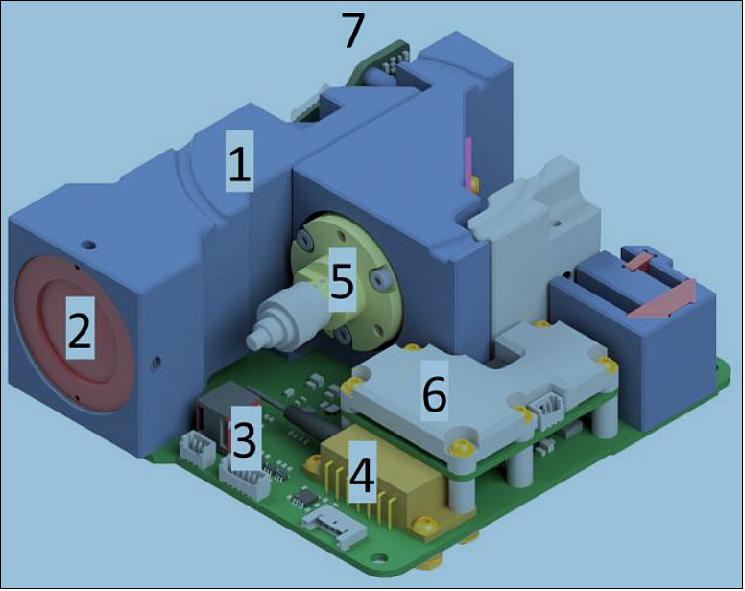
Description of Figure 2: The blue parts are the optomechanics (1) which are the mechanical mounts and housings for the optical elements highlighted in light red (2). Below in green one can see the electronics mainboard (3). The transmission system consists of the laser source in orange (4) and the transmit collimator in yellow (5). The driver electronics sits on the small, green PCB (Printed Circuit Board) with a passive cooling element on top in gray (6). The receiver sensor is located on a separated PCB at the back side of the terminal (7).
The main part of the system is the optical path. As experienced from past projects the alignment process of transmission and receiving beam, so called Tx-/Rx-alignment gets exponentially more complicated as the degrees of freedom increase. Therefore, DLR decided to build a compact optomechanics subsystem which integrates all optical components into two aluminum blocks, without any adjustable mechanisms. Thus, DLR had to completely rely on the accuracy of the manufacturer of the optomechanics. A tolerance analysis of the optical system, which considered the manufacturing tolerances showed, that no further alignment mechanisms are necessary. For the Tx-/Rx-alignment a collimator with a tumbling plate was evaluated, which provides the only necessary degree of freedom for the alignment.
Inside the 3U CubeSat, several competing standards can be found. One of the most common standards is the PC/104 standard. The mechanical dimensions and the mounting positions of the OSIRIS4CubeSat payload are compatible to this standard. The PC/104 standard also defines a 104 pin-connector where the name of the standard comes from. As this connector is relatively large compared to other solutions DLR decided to use compact Commercial Off The Shelf (COTS) connectors which are compatible to most harnesses used in CubeSats. Adapter boards from PC/104 to the interfaces used in OSIRIS4CubeSat are also commercially available.
The OSIRIS4CubeSat is equipped with an own microcontroller. This microcontroller is mainly responsible for the control loop of the FPA inside the system. Every resource intensive calculation like coding or data handling is outsourced to the satellite bus. Telemetry and Telecommands (TM/TC) are sent to/from OSIRIS4CubeSat via an UART interface. The downlink data itself is transmitted via a Low Voltage Differential Signal (LVDS). To be able to reprogram the microcontroller in space, a Joint Test Action Group (JTAG) interface is implemented.
Payload Development
To minimize the costs and development time, two identical models of OSIRIS4CubeSat were built in phase 3, one EQM (Engineering Qualification Model) and one FM (Flight Model). Having two identical models allowed to perform the whole test and qualification process with the EQM and building up the FM in parallel. The preparations in phase 1 and 2, allowed starting the assembly of both models straight after the CDR. Using COTS components enabled a development in a short time as long lead items could be avoided or identified in earlier phases. Even though the components are not space qualified they were selected with the view on the harsh environment. The evaluation was focused on heritage components in a harsh environments like in automotive systems. They are not qualified for space but it is proven that they survive in hard environmental conditions.
Using COTS components has further advantages that they are easily replaceable. Considering electronic parts with the same footprints allows replacing them when a non-conformance occurs or results of a functional test show that the electronics have to be changed. Without changing the whole circuit design the parts can easily be replaced.
The modular design of the payload Using COTS components has further advantages that they are easily replaceable. Considering electronic parts with the same footprints allows replacing them when a non-conformance occurs or results of a functional test show that the electronics have to be changed. Without changing the whole circuit design the parts can easily be replaced.
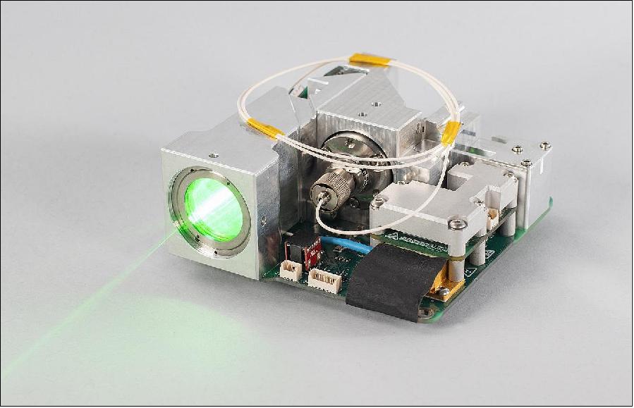
Size | 95 x 95 x 30 mm (~0.3U) |
Mass | <400 g |
Power | 8.5 W max |
Data rate | up to 100 Mbit/s |
Fine pointing assembly | ±1º |
CubeL (Laser CubeSat)
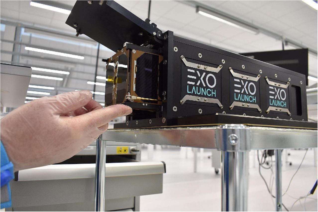
So far, laser terminals were too bulky and too power hungry to integrate them into a 3U CubeSat form factor. But the launch of the PIXL-1 mission opens new horizons in satellite communications by extending the mission capabilities of CubeSats with data rates of up to 100 Mbit/s.
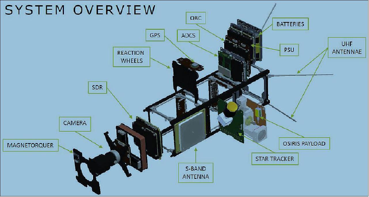
The goal of DLR's PIXL-1 demonstration mission is to test and qualify a highly compact and power efficient laser communication payload, namely OSIRIS4CubeSat on a 3U CubeSat of GomSpace.
In addition, a camera system is installed on CubeL. It can be used for an end-to-end demonstration ranging from image acquisition, over optical transmission from Space to Earth, to processing the images on ground.

Launch
PIXL-1, a 3U CubeSat mission of DLR, was launched as one of many payloads (total of 143 satellites) on the Transporter-1 mission of SpaceX from the Cape Canaveral Space Force Station (SLC-40) in Florida on 24 January 2021 at 15:00 UTC. 4)
List of all 143 Satellites Launched on the Transporter-1 Mission of SpaceX 5) 6) 7)
• 48 SuperDove satellites of Planet, San Francisco• 36 SpaceBEE satellites of Swarm Technologies, built to a 0.25U CubeSat form factor.
• 10 Starlink satellites for SpaceX (note: the launch of the 10 Starlink satellites is described in the Starlink file on the eoPortal)
• 8 GEN1 satellites of Kepler Communications, Toronto, Canada.
• 8 Lemur-2 satellites, 3U CubeSats, of Spire Global, San Francisco. The Lemur-2 satellites carry two payloads: STRATOS GPS radio occultation payload and the SENSE AIS-receiver.
• 5 Astrocast satellites
• 3 HawkEye 360 satellites
• 3 ICEYE X-band SAR satellites of the ICEYE SAR constellation, Finland.
• 3 V-R3x, 3 demonstration 1U CubeSats of NASA. The V-R3x tech demo will demonstrate low-cost and low-SWaP autonomous high-speed cross-linking, ranging, coordinated radiation measurements, and relative topology recovery utilizing three (3) 1U CubeSats.
• 3 ARCE-1 (Articulated Reconnaissance and Communications Expedition) 0.5 U CubeSats of USF (University of South Florida) to test inter-satellite networked communications.
• 2 Capella Space SAR (Synthetic Aperture Radar) satellites
• Sherpa-FX1 space tug, developed by Spaceflight, is a free flying satellite deployer. Sherpa-FX1 will deploy the HawkEye, Astrocast, PTD-1, 3 ARCE-1 and Prometheus-2 satellites. In addition to the separable payloads, there will be up to four, approximately 1U-sized, hosted payloads. These hosted payloads will be non-separating and will deorbit with the Sherpa-FX1 structure.
• D-Orbit's ION-SCV (In Orbit Now - Satellite Carrier Vehicle) Laurentius space tug. During the mission, named PULSE, the vehicle will deploy 20 satellites including 8 SuperDove satellites from Earth imaging company Planet Labs, and it will then perform the in-orbit demonstration of several payloads including an optical instrument from EICAS Automazione and one from Instituto de Astrofísica de Canarias (IAC). [Ref. 6), 7)]
• iQPS-2 (Institute for Q-shu Pioneers of Space-2). A X-band SAR satellite with a mass of ~100 kg for iQPS of Japan
• YUSAT (Yushan Satellite 1), a 1.5U CubeSat of the National Taiwan Ocean University, Taiwan.
• IDEASSAT (Ionospheric Dynamics Explorer and Attitude Subsystem Satellite), a 3U CubeSat of the National Central University), Taiwan.
• UVQS-SAT (UltraViolet & infrared Sensors at high Quantum efficiency onboard a small Satellite), a 1U CubeSat of LATMOS of France.
• ASELSAT, a 3U CubeSat of ASELSAN, Turkey
• Hiber Four, a 3U CubeSat of Hiber, the Netherlands
• SOMP2b (Student On-Orbit Measurement Project 2b) of TU Dresden of Germany
• CubeL, a 3U CubeSat of DLR (3.4 kg), partnered with Tesat, Germany to test laser downlink communications for CubeSats.
• Charlie, a 6U CubeSat of U.S.-based Aurora Insight
• GHGSat-C2 (Hugo) of GHGSat, Montreal, Canada. The microsatellite (16 kg) was built by UTIAS/SFL
• PTD-1 (Pathfinder Technology Demonstrator-1), a 6U CubeSat (11 kg) of NASA/ARC
• Prometheus-2, a 1.5U CubeSat for technology development and demonstration of LANL (Los Alamos National Laboratory)
Orbit
SSO orbit of Rideshare mission: — SpaceX sent this mission with its 10 Starlink satellites into a polar SSO (Sun-Synchronous Orbit) with permission of the FCC (Federal Communications Commission). Altitude of 560 km and inclination of 97.6º 8)
The Falcon 9 rocket soared toward the southeast from the launch pad at Cape Canaveral, then vectored its thrust to fly on a coast-hugging trajectory toward South Florida, before flying over Cuba, the Caribbean Sea, and Central America. The unusual trajectory was similar to the track followed by a Falcon 9 launch in August 2020, which was the first launch since the 1960s from Florida's Space Coast to head into a polar orbit.
Mission Status
• As of early February 2021, the PIXL-1 mission is in commissioning after completing LEOP (Launch and Early Orbit Phase) activities. 9)
Ground Segment
Operations
CubeL is being operated by German Space Operations Center (GSOC) of DLR. CubeL will be the first COTS CubeSat to be operated by GSOC, which in itself poses a few challenges: CubeSats commonly operate in the UHF-band spectrum and the satellite's native communication protocol is the CubeSat Space Protocol (CSP), which is an open source protocol developed and maintained by the University of Aalborg, Denmark and has been adapted and extended by GomSpace. Both technologies had yet to be supported by GSOC.
The primary mission objective of PIXL-1 is the successful in-orbit demonstration (IOD) of the OSIRIS4CubeSat module's downlink capabilities and reliability. In order to establish operational readiness within the limited designated timeframe, whilst keeping risk as low as possible a CSP compatible COTS UHF ground segment was procured and integrated into the GSOC facilities. The long operational heritage of GomSpace ground segment hardware and software promise minimal setup times and all components have been proven to work reliably out of the box.
During phase E2a, CubeL will be operated only via UHF utilizing the GomSpace NanoCom AS100 dual Yagi antenna, GS100 dual-radio ground station transceiver, and the MS100 mission computer hosting the CSP monitoring and control system. These components form the baseline for the E2a ground segment, which is further augmented by GSOC MUM (multi-mission) components. GSOC security policy requires external hardware and software to be isolated in separate networks and thus may not be integrated into the MUM environment directly.
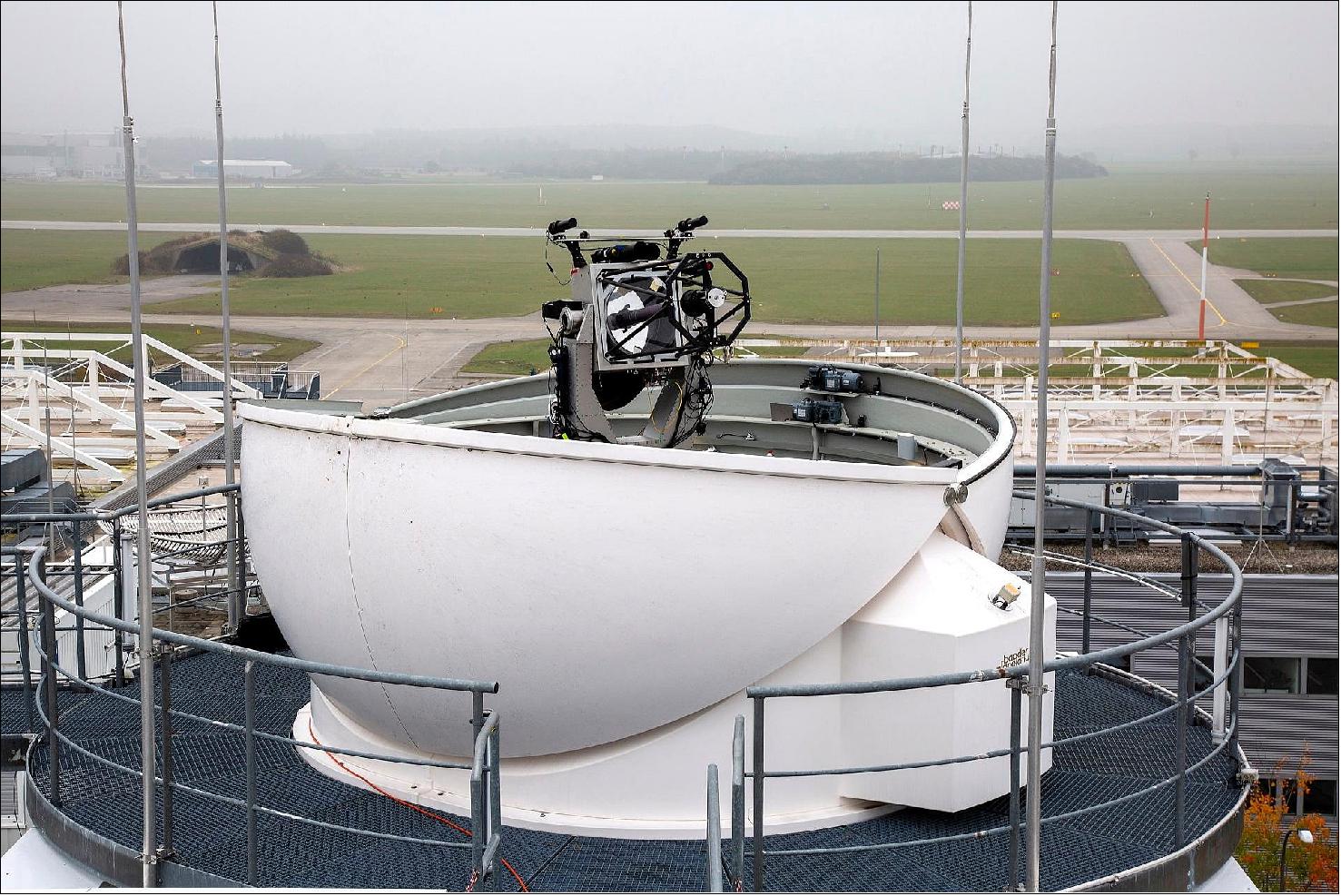
OGS (Optical Ground Stations) of IKN
One major challenge in laser-based communications is the weather, as laser signals cannot be transmitted through clouds. A worldwide network of optical ground stations, mainly situated at locations with little cloud cover, is to be set up to overcome this limitation. DLR is supporting this approach through its pioneering PIXL-1 mission, and will be testing locations and expanding the receiving network over the coming months. The network's first two ground stations are currently being established at two European locations by the GSOC in collaboration with an industry partner (Ref. 4).
Two different radio frequency bands are used for communicating with and controlling the PIXL-1 small satellite. During the initial in-orbit demonstration phase, communications will be conducted in the Ultra-High Frequency (UHF) band, using a new GSOC antenna set up for that purpose. During the mission itself, the satellite will communicate in S-band frequencies, so that the control centre will be able to use its normal ground stations and integrate the satellite into the standard processes as smoothly as possible. During regular operations, GSOC will control the satellite from Oberpfaffenhofen, calibrate the laser terminal and ensure that the data are forwarded to researchers at the Institute of Communications and Navigation.
DLR and TESAT have been working very closely and successfully together since 2016. Through its Optical Space Infrared Downlink System (OSIRIS) program, the Institute of Communications and Navigation is developing miniaturized laser communications terminals with compact designs. These can be used for direct optical downlinks from the satellite to Earth. As a client, TESAT has been involved in the development work from the start. The company is a world leader in optical satellite communications and is planning to expand the market for small satellites in the context of these developments. The launch of PIXL-1 marks a major advancement for this technology. After completion of the development phase, TESAT will commence mass production of the compact satellite laser terminal.
"At TESAT, we have a clear vision of our products overcoming borders and bringing people together. We have come one crucial step closer to achieving this with the launch of PIXL-1. The CubeLCT is the result of the highly successful cooperation between the DLR Institute of Communications and Navigation and TESAT," says Marc Steckling, CEO of Tesat-Spacecom.
TOGS (Transportable Optical Ground Station)
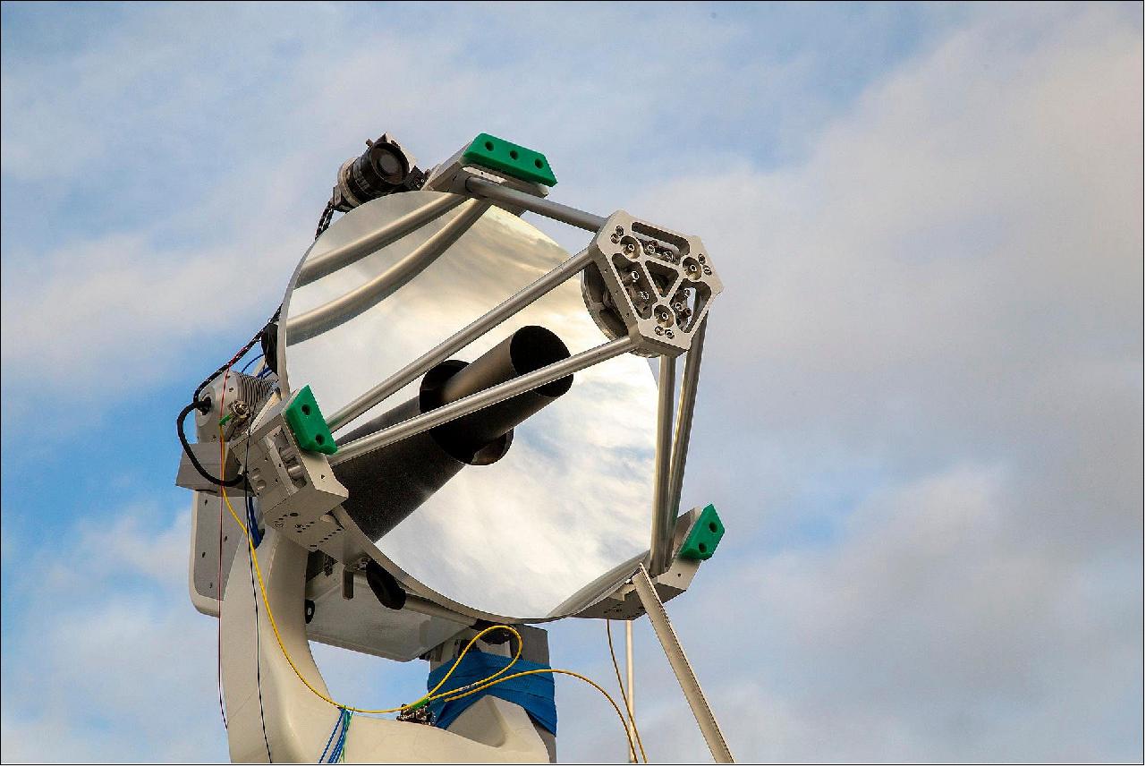
TOGS is a versatile modular instrument that can be used for a variety of experimental optical downlink and uplink scenarios as well as for assessing the atmospheric optical channel.
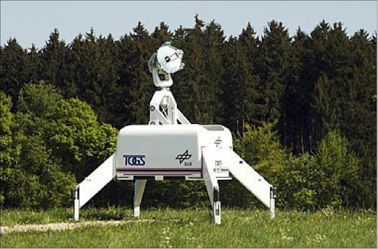
TOGS was designed by DLR/IKN in the years 2010 and 2011. One major design goal was a small and lightweight construction, which can be easily transported to sites all over the world. The structure had to be stiff enough to reach the accuracy needed for optical communications.
The main component of the TOGS is a 60 cm aluminum Ritchie-Chrétien Telescope, which can be deployed to a height of 3.5 m by a foldable mast construction. A special requirement for the telescope in a mobile system was to maximize the mirror diameter while having a short overall length. Therefore, a special design of a Ritchie-Chrétien-Telescope was developed. To shield the telescope from dirt and shocks during transportation, it is stowed in a compartment made of carbon fiber, which is damped by shock-absorbing mount elements.
One major challenge for a transportable ground station is the rapid determination of its position and attitude. Both are needed for rapid target pointing. An advanced system based on satellite navigation and attitude sensors is used for automatic identification of these parameters and allows a quick installation of the ground station. In addition, a GPS-positioned laser reflector has been developed to allow a rapid and precise alignment.
Possible mission scenarios for the ground station include links to and from aircraft, UAVs, and satellites. Another field of operation is the evaluation of new sites for fixed ground stations in terms of cloud coverage and weather statistics.
Further applications of TOGS are downlinks from observation platforms after a disaster. Pictures of the disaster site may be taken by an aircraft and directly transmitted to the disaster area by an optical link. The real-time information is a fundamental requisite to coordinate emergency units.
Some Background
DLR-IKN (Institute for Communication and Navigation) has been conducting research in the field of optical free space communications through the atmosphere for many years. Typical applications are high rate data transmissions from aircraft or satellites to an optical ground station (>> 1 Gbit/s). For the design and optimization of communication systems, channel measurements are an extremely important prerequisite. In addition, developed concepts, such as methods for single-mode fiber coupling or diversity methods for suppressing signal interference, must be set up and demonstrated.
The current telescope with the 40 cm primary mirror was used in many experiments to gain valuable knowledge about the atmospheric channel and to demonstrate various technologies. Some examples are experiments and demonstrations with high-speed optical communication between aircraft, satellites and ground stations, as well as quantum key distribution between aircraft and ground. The optical ground station will be upgraded for future developments and to improve the quality of the measurements. A new telescope system with a larger primary mirror and Coudé feed for the optical beam path into the laboratory is set up (Coudé laboratory). This allows experiments to be set up efficiently in a laboratory environment, which enables complicated experiments, e.g. in the field of adaptive optics, to be carried out. In addition, there is a test source for test measurements over long distances and an ensemble of atmosphere measuring devices (atmosphere measuring garden) for characterizing the location.
This new station will be used for the development and investigation of future optical satellite and aircraft connections and can be used in national and international measurement campaigns.
Implementation Overview
The structure of the installation is divided into three parts: the Coudé laboratory, the test transmitter and the atmosphere measuring station.
Figure 11 shows the conceptual diagram.
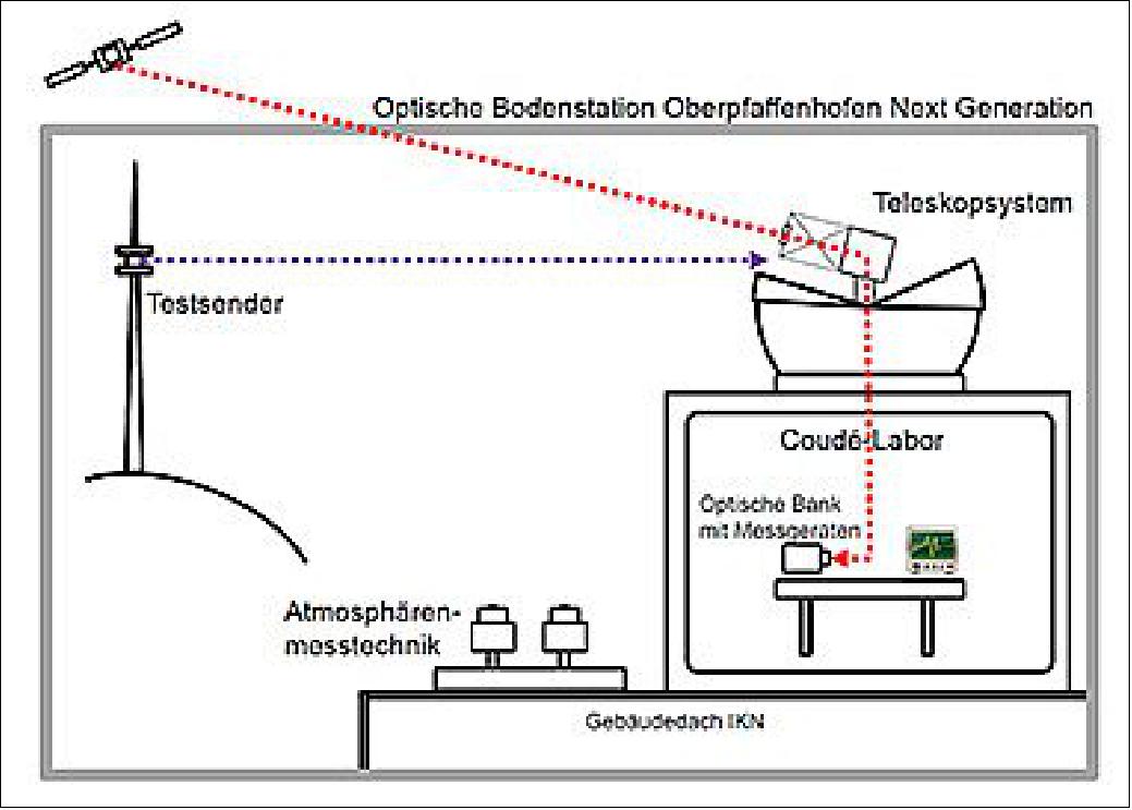
The Coudé laboratory offers the possibility to measure the laser beam disturbed by the atmosphere during an experiment (satellite or aircraft connection) with different instruments. Since these instruments in the Coudé arrangement can not be set up directly on the telescope, but now vibration-decoupled on a separate table, measurements can be carried out that require the highest level of precision.
The test source enables the adjustment and calibration of the measuring devices in the Coudé laboratory, as well as the testing of developments in a static scenario. It will be set up at a distance of ~7 km from the ground station on the antenna platform of the Fürstenfeldbruck 2 radio tower (Schöngeising municipality) and equipped with various lasers, signal and data sources.
The atmosphere measuring garden contains several standard measuring instruments, which are set up at the location of the optical ground station to characterize the atmosphere. The instruments will provide operational measurements of the air turbulence, the atmospheric transmission and the relevant weather parameters, which are necessary for the evaluation of the measurement data obtained during a satellite and aircraft experiment. These include, for example, a scintillometer and a sodar. Both are used to model turbulence profiles.
References
1) "About the mission: PIXL-1," TESAT, URL: https://tested/PIXL
2) Benjamin Rödiger, Christian Menninger, Christian Fuchs, Lukas Grillmayer, Saskia Arnold, Christoph Rochow, Philipp Wertz, Christopher Schmidt, "High data-rate optical communication payload for CubeSats," Proceedings of SPIE 11506, 'Laser Communication and Propagation through the Atmosphere and Oceans IX,' Volume 11506, 22 August 2020 https://doi.org/10.1117/12.2567035
3) Information provided by Benjamin Rödiger of DLR.
4) "A pioneering launch – compact satellite PIXL-1 carries the world's smallest laser terminal into orbit," DLR, 24 January 2021, URL: https://www.dlr.de/content/en/articles/news/2021/01/
20210124_pioneering-launch-compact-satellite-with-smallest-laser-terminal.html
5) Stephen Clark, "SpaceX smashes record with launch of 143 small satellites," Spaceflight Now, 24 January 2021, URL: https://spaceflightnow.com/2021/01/24/
spacex-launches-record-setting-rideshare-mission-with-143-small-satellites/
6) The PULSE mission has launched," D-Orbit, URL: https://www.dorbit.space/
7) "D-Orbit's ION SCV Laurentius Smallsat Launched By Spacex," Satnews, 24 January 2021, URL: https://news.satnews.com/2021/01/24/
d-orbits-ion-scv-laurentius-smallsat-launched-by-spacex/
8) Jeff Foust, "FCC grants permission for polar launch of Starlink satellites," SpaceNews, 9 January 2021, URL: https://spacenews.com/fcc-grants-permission-for-polar-launch-of-starlink-satellites/
9) Information provided by Benjamin Rödiger of DLR/IKN
The information compiled and edited in this article was provided by Herbert J. Kramer from his documentation of: "Observation of the Earth and Its Environment: Survey of Missions and Sensors" (Springer Verlag) as well as many other sources after the publication of the 4th edition in 2002. - Comments and corrections to this article are always welcome for further updates (eoportal@symbios.space).
Payload Launch Mission Status Ground Segment References Back to top