Sich-1M (Modified)
EO
Atmosphere
Ocean
Liquid water and precipitation rate
Quick facts
Overview
| Mission type | EO |
| Agency | NSAU |
| Mission status | Mission complete |
| Launch date | 31 Aug 1995 |
| End of life date | 15 Apr 2006 |
| Measurement domain | Atmosphere, Ocean, Land, Snow & Ice |
| Measurement category | Liquid water and precipitation rate, Cloud particle properties and profile, Multi-purpose imagery (ocean), Radiation budget, Multi-purpose imagery (land), Vegetation, Albedo and reflectance, Atmospheric Humidity Fields, Ocean topography/currents, Sea ice cover, edge and thickness, Snow cover, edge and depth, Ocean surface winds, Ocean wave height and spectrum, Ice sheet topography |
| Measurement detailed | Ocean imagery and water leaving spectral radiance, Precipitation intensity at the surface (liquid or solid), Cloud liquid water (column/profile), Land surface imagery, Vegetation type, Earth surface albedo, Short-wave Earth surface bi-directional reflectance, Atmospheric specific humidity (column/profile), Wind vector over sea surface (horizontal), Sea-ice cover, Snow cover, Sea-ice thickness, Significant wave height, Ocean dynamic topography, Sea-ice sheet topography |
| Instruments | MTVZA-OK, RLSBO, KONDOR-2, MSU-M, MSU-S, RM-08, MSU-E, MSU-EU, Variant |
| Instrument type | Imaging multi-spectral radiometers (vis/IR), High resolution optical imagers, Magnetic field, Imaging multi-spectral radiometers (passive microwave), Data collection, Imaging microwave radars, Atmospheric temperature and humidity sounders |
| CEOS EO Handbook | See Sich-1M (Modified) summary |
Sich-1M (Modified)
Overview
Sich-1M is a cooperative Ukrainian-Russian multi-purpose EO (Earth Observation) mission based on a 2001 agreement of former Rosaviakosmos (Russian Space Agency), now Roskosmos, and NSAU (National Space Agency of Ukraine). The agreement is considered as part of the Ukrainian National Space Program approved by the parliament on Oct. 27, 2002. The Sich-1M project is an upgrade development of the Sich-1 satellite, launched Aug. 31, 1995 (of Okean-O1 heritage). Sich is the Ukrainian name for `owl'. The overall objective of the mission is monitoring of the Earth and its oceans, study of geology, climate, and ecology. The requirements call for: 1)
• Monitoring of vegetation and soil types and condition
• Research and study of geological structures
• Monitoring of soil and water reservoir pollution
• Snow cover boundaries and condition, ice patrol
• Research of global distribution of ionospheric electrical fields and currents and plasma convective motions
• Wave measurement in polar cusp plasma
• Detection of ELF-VLF electromagnetic radiation caused by the Earth seismic activity
• Research of ionosphere response to subsonic wave effect
• Active experiments with high-power acoustic radiation ground sources
• Plasma modification in the vicinity of the spacecraft by the onboard radar irradiation
• Comparison between independent experimental techniques for the measurement of electric current density in the ionosphere.
Spacecraft
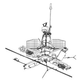
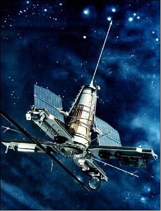
The Sich-1M spacecraft has been built and integrated by the State Design Office Yuzhnoye of Dniepropetrosvk, Ukraine (also provision of the launch vehicle Tsyklon-3). The satellite is gravitationally stabilized (gravity boom) using the structural platform of the Sich-1 satellite and the Okean-O1 satellite series. The spacecraft orientation accuracy is 1º in roll, 2º in yaw, and 3º in the pitch axis. The accuracy of satellite attitude determination is within 0.5º. The spacecraft flies also a GPS receiver. Sich-1M has a daily average power consumption of 380 W. It has a launch mass of 2223 kg and a design life if one year with a goal of 3 years. 2) 3)
Launch
A launch of the Sich-1M spacecraft took place on Dec. 24, 2004 from the Plesetsk cosmodrome, Russia, on a Tsyklon-3 (Cyclone-3) launch vehicle. - A secondary (piggyback) payload on this launch vehicle is MS-1-TK (Microsatellite-1) of NSAU.
Orbit
Nominal orbit: Non-sunsynchronous polar near-circular orbit, altitude = 650 km ±30 km, inclination = 82.5º, period = 98.7 min.
Note: The remote-sensing Sich-1M spacecraft was supposed to be delivered into a 681 x 640 km nominal orbit with the inclination of 82.5º; however, initial radar observations by NORAD found the third stage of the launch vehicle and both payloads in the 281 x 639 km orbit. It could be an indication that the second burn of the Tsyklon-3's third stage failed, leaving the spacecraft in the useless and unstable orbit. The second ignition of the third stage engine to circularize the orbit was expected to take place 39 minutes after the launch. Unfortunately, Sich-1M doesn't have onboard propulsion to circularize its orbit for stable Earth observations.
In Feb. 2005, NSAU is reporting a Sich-1M orbit of 644 km x 285 km with an orbital period of 93.26 minutes and an inclination of 82.57º. Obviously, the spacecraft and its payload is being operated in this elliptical orbit. 4)
RF communications: ROSHYDROMET/SRC PLANETA maintains data acquisition at three locations in Russia:
1) 1.7 GHz radio link with data rates of 665.4 or 1330.8 kbit/s, transmitter power: 6 W
2) 2.2 GHz radio link with a data rate of 6 Mbit/s, transmitter power of 9 W
3) RTVK-M (Radio and Television Complex)-Memory for 1.7 and 2.2 GHz radio links. The storage capacity is 192 Mbit. The downlink is an analog system in VHF-band with a downlink frequency of 137.4 MHz and a bandwidth of 2.4 kHz.
4) An X-band downlink of 8.2 GHz is also being used.
Mission Status
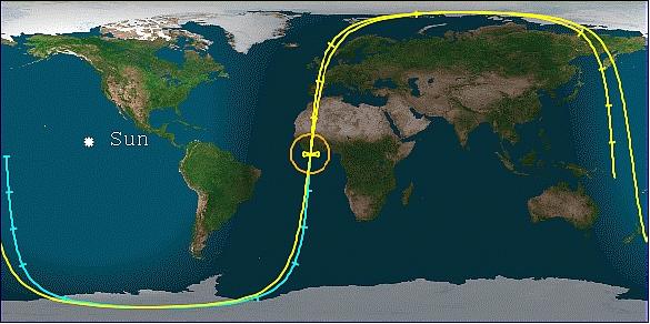
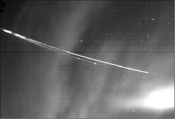
• The Sich-1M spacecraft with its low perigee experienced a decaying orbit. The spacecraft reentrered the atmosphere on April 15, 2006 (impact in the southern Atlantic Ocean off the coast of West Africa. The comet-like reentry trail was recorded by the Meteorological Service of Spain (Figure 4). 5)
• The Sich-1M spacecraft stopped operations on August 8, 2005 (due to its unfavorable and decaying orbit). 6)
Sensor Complement
RLSBO (Side Looking Real Aperture Radar)
RLSBO was built by Kharkov IRE, Ukraine. RLSBO was the prime sensor of the Okean series (11.1 m antenna length). Objective: Earth surface monitoring, snow coverage sea ice mapping. Wavelength/frequency: 3.14 cm/9.7 GHz, X-band; data resolution = 1.7 km - 2.8 km in flight direction, = 1.3 km - 0.7 km in cross track direction; swath width of 700 km (note: the swath was widened from 450 km to 700 km). The swath width is provided in two operational modes: 450 km or 700 km. The swath location is to the left of the spacecraft flight direction with a shift of 230 km to the left from nadir.
RM-08 (Passive Microwave Scanning Radiometer)
The instrument was built by Kharkov IRE, Ukraine. Wavelength/frequency: 0.8 cm / 36.6 GHz; swath = 550 km. Objective: monitoring of atmospheric vapor, sea ice, and sea surface temperature (SST) with an accuracy of 1-2 K. Temperature measurement ranges of 110 to 330 K and 150 to 250 K. The average size of a resolution cell at nadir is 25 km x 25 km.
MSU-M (Multispectral Scanner of low resolution)
MSU-M was built by ISDE, Moscow. Resolution = 1.5 x 1.8 km, swath = 2000 km. Objective: cloud monitoring and sea surface temperature. MSU-M is a low-resolution optical imager with the following spectral ranges: 0.5 - 0.6 µm; 0.6 - 0.7 µm; 0.7 - 0.8 µm; 0.8 - 1.0 µm
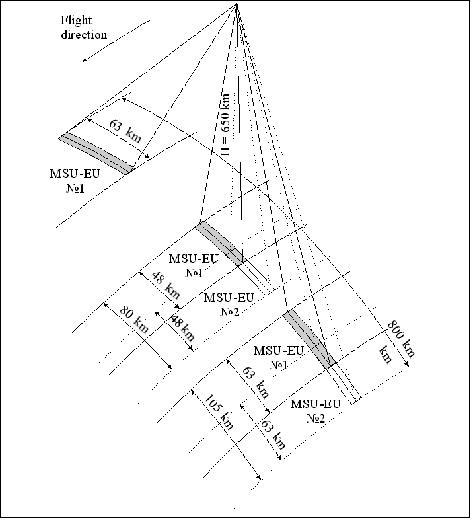
MSU-EU1 & MSU-EU2 (Multispectral high-resolution Optoelectronic Scanning Radiometers)
Linear resolution along/across track |
|
Loch-in zone | 800 km |
Swath width of one scanner: at nadir | 48 km |
Swath width of one scanner: at nadir | 80 km |
Spectral channel 1 | 0.50 - 0.59 µm |
Geometry of the swaths | The scanning is implemented perpendicular to the flight direction. The optical axis of each equipment can displace on ±30º in steps of 2º within the limits of a lock-in zone |
SNR at maximum radiance | 100 |
Operating modes: | |
Selection of an optical axis deflection angle | ±30º |
Selection of configuration of instruments | MSU-EU1 or MSU-EU2 or both devices |
Data transmission mode | |
Direct transmission (DD) in a transmitter's range of ground station | Format BIS-S, frequency of 8.2 GHz |
Recording (R) with subsequent reproduction(DR) | Format BIS-S, frequency of 8.2 GHz |
MTVZA-OK (Combined Microwave-Optical Imaging/Sounding Radiometer)
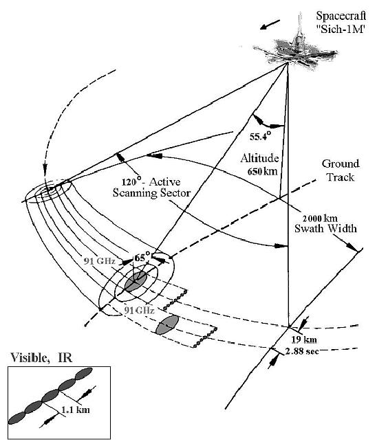
MTVZA-OK is of MTVZA (Microwave Imaging/Sounding Radiometer) heritage flown on Meteor-3M. Objective: Atmospheric temperature and humidity profiling, monitoring of ice and snow, sea surface wind speed, precipitation, and ocean color. The design features a conical-scanning radiometer with a period of 2.88 s (instability of scanning period is 10-4). 7) 8) 9)
Microwave system: All microwave radiometer channels are switched to a single feedhorn antenna. A total-power radiometer configuration is employed. The channels of 6.9-48 GHz are direct amplification radiometers. The channels of 52-57 GHz, 91 GHz and 183 GHz are built as superheterodyne receivers using balanced mixers. MTVZA-OK microwave performance and frequency channel characteristics are shown in Table 3.
The antenna system consists of an offset parabolic reflector of dimension 60 cm, illuminated by a broadband feedhorn antenna. To remain the invariant of viewing angle and polarization in the scanning sector, the reflector and feedhorn antenna are mounted on a scanning platform, containing the radiometers, digital data subsystem, power and signal transfer assembly, which rotates continuously about an axis parallel to the local spacecraft vertical. The power, commands, all data, timing and telemetry signals pass through slip ring connectors to the rotating assembly.
The microwave calibration system consists of a small mirror and a hot reference absorber, both are not rotated with scanning platform. They are positioned off axis such that they pass between the feedhorn and the parabolic reflector, occulting the feedhorn once each scan. The mirror reflects cold 2.7 K cosmic background radiation into the feedhorn, thus serving along with the hot reference absorber. This scheme provides an overall end-to-end absolute calibration, which includes the feedhorn.
Optical system: This is a five-channel radiometer providing four solar channels in the visible region and a thermal infrared channel or MWIR (Mid-Wave Infrared) region. All channel detectors are built on linear charge-coupled devices (CCDs). The four solar channels are using a silicon detector, while the thermal channel (3.55-3.93 µm) is using an InSb detector. The thermal channel detector is cooled to 80 K. The NEDT is < 0.2 K for a background temperature of 300 K. The four solar channels are characterized by an SNR (Signal-to-Noise Ratio) of > 8:1 for an albedo of 0.5%.
Parameter | Optical System | Microwave System |
Nr. of spectral or frequency bands | 4 in VIS and 1 in SWIR | 22 MW channels |
Spectral range | 0.37-0.45, 0.45-0.51, 0.58-0.68, | 6.9, 10.6, 18.7, 23.8, 31, 36.5, 42, 48, 52.3-57.0, 89, 183.31 (GHz) |
Spatial resolution | 1.1 km | 19-260 km |
Swath width; data rate | 2000 km; 665.4 kbit/s | |
Conical scanning period | 2.88 s | |
Instrument mass; power | 120 kg; 200 W | |
Cha. No | Center Frequency (GHz) | No of pass bands | Bandwidth (MHz) | Effective | Imagery Pixel size (km x km) | Sensitivity (K/pixel) | Peak sensitivity altitude (km) |
1 | 6.9 | 1 | 350 | 112x260 | 38x38 | 0.3 | - |
9 | 52.80 | 1 | 400 | 18x43 | 38x38 | 0.4 | 2 |
14 | 57.290344±0.3222±0.1 | 4 | 50 | 18x43 | 57x57 | 0.4 | 20 |
19 | 91.65 | 2 | 2000 | 12x28 | 19x19 | 0.6 | Surface |
20 | 1.83.31±7.0 | 2 | 1500 | 8x19 | 38x38 | 0.5 | 1.5 |
• Channels 1-8, and 19 (imager) operate on both vertical and horizontal polarization
• Channels 9-13, and 20-21 (sounder) operate on vertical polarization
• Channels 14-18 (sounder) operate on horizontal polarization
• Channels 2, 3, and 6 (polarimeter) operate to determine four Stokes parameters (next version MTVZA-GY for spacecraft ”Meteor-M”, a launch is planned for 2008).

Scanning geometry: The MTVZA-OK scanning platform rotates continuously about an axis parallel to the local spacecraft vertical with a period of 2.88 s during which the subsatellite point travels 19 km. The scan direction is from the right to the left when looking in the forward direction of the spacecraft, with the active scanning sector 120º, resulting in a swath width of 2000 km. The viewing angle is 55.4º and the incidence angle with respect to the Earth surface is 65º.
Variant ("Version") Instrument Package
The overall objective is “Investigation of the lithosphere-atmosphere-ionosphere-magnetosphere coupling” (space environment monitoring), i.e. current density measurements in ionospheric-magnetospheric plasmas. Study of space weather and of fine seismogenic effects in the ionosphere. Variant is an international joint scientific project of Great Britain, Poland, France, Russia, and Ukraine [LC-IKD (Lviv Center, Institute of Space Research)]. 10) 11) 12) 13)
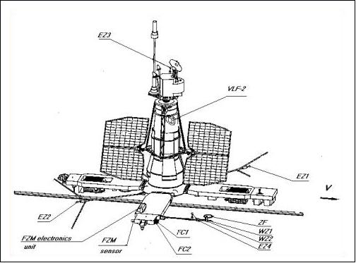
The Variant scientific payload includes three instruments for registration of space current density: a split Langmuir probe, a Rogovsky coil and a Faraday cup. The first two of these instruments are dedicated to measure current density variations and the last the particle fluxes. The equipment also includes sensors for measurements of the electric and magnetic field fluctuations in the frequency range from 0.1 Hz to 40 kHz. The Variant payload measurements will be compared to those of the seismic payload flown on the DEMETER mission. The main objectives of the Variant mission are as follows:
• Direct comparison of the spectral characteristics of the electric and magnetic fields with the characteristics of the field aligned currents in the polar regions; mapping of the field aligned current distribution
• Comparative study of the field aligned current structures with the characteristics of the ionospheric convection observed by the system of radars SuperDARN (Super Dual Auroral Radar Network)
• Comparative study of technological problems associated with different techniques of current density measurements.
Device | Measurement | Designed by |
Wave Probe WZ | Electric current density J: | LC ISR, Ukraine, (V. Korepanov) |
Rogovsky Belt ZF | Electric current density J: | LPCE/CNRS, France |
Electrical probe EZ | Electric field vector E: | LC ISR, Ukraine, (V. Korepanov) |
Faraday cylinder FC | Electric current density J: | Sheffield University , UK |
DC magnetometer FCM (also FZM) | Magnetic field vector B | LC ISR, Ukraine |
References
1) A. Fournier-Sicre, T. Suslova, A. Krasnov, “Sich-1M - A Russian-Ukrainian project,” ESA “News from Moscow,” Special Issue No 9, July 7, 2003, pp. 24-25
3) http://www.geocities.jp/semsweb/Sich-1M.html
4) http://www.nkau.gov.ua/nsau/newsnsau.nsf/0/FC789BADD4D1DAC2C2256F9E00357CE0?OpenDocument&Lang=E
5) http://reentrynews.aero.org/2004052a.html
6) OMZ-NTS (Research Center for Earth Monitoring) of RosKosmos website, URL: https://web.archive.org/web/20150626015639/http://eng.ntsomz.ru/ks_dzz/satellites/sich_1m
7) V. V. Boldyrev, I. V. Cherny, G. M. Chernyavsky, S. G. Danilov, O .Yu. Kazantsev, V. P. Nakonechny, S. Yu. Pantsov, Yu. N. Prokhorov, N. I. Strelnikov, “Optical-Microwave Imager/Sounder MTVZA-OK of Spacecraft “Sich-1M“, Proceedings of the 31st International Symposium on Remote Sensing of Environment (ISRSE) at NIERSC (Nansen International Environmental and Remote Sensing Center), Saint Petersburg, Russia, June 20-24, 2005, URL: http://www.isprs.org/publications/related/ISRSE/html/papers/1028.pdf
8) A. B. Uspensky,V. V. Asmus, V. N. Dyaduchenko, O. E. Milekhin, “Russian Environmental Satellites: Status and Development Perspectives,” 13th ITSC (International TOVS Study Conference), Sainte. Adèle, Quebec, Canada, Oct 28 - Nov. 4, 2003, http://cimss.ssec.wisc.edu/itwg/itsc/itsc13/session6/6_3_uspensky.pdf
9) I. V. Cherny, G. M. Chernyavsky, “Combined optical-microwave imager/sounder MTVZA-OK,” Proceedings of IGARSS'01, Sidney, Australia, July 9-13, 2001
10) http://www.isr.lviv.ua/variant.htm
11) V. Korepanov, O. Negoda, G. Lizunov, H. Alleyne, et al., “Project Variant: Current and Field Measurements onboard Sich-1M Satellite,” http://www.isr.lviv.ua/26.pdf
12) V. Korepanov, “Remote Sensing as a Tool of Seismic Hazards Monitoring,” 14th International Conference on Applied Geologic Remote Sensing, Las Vegas, Nevada, 6-8 Nov. 6-8, 2000, URL: http://194.44.232.21/4.pdf
13) V. Korepanov, O. Negoda, G. Lizunov, H. Alleyne, et al., “Variant: current and field measurements on board Sich-1M satellite,” Advances in Space Research, Vol. 25, No 7-8, 2000, pp. 1337-1342, 2000
The information compiled and edited in this article was provided by Herbert J. Kramer from his documentation of: ”Observation of the Earth and Its Environment: Survey of Missions and Sensors” (Springer Verlag) as well as many other sources after the publication of the 4th edition in 2002. - Comments and corrections to this article are always welcome for further updates (eoportal@symbios.space).