Source (Stuttgart Operated University Research CubeSat for Evaluation and Education)
Non-EO
Education
Technology and Research
Quick facts
Overview
| Mission type | Non-EO |
SOURCE (Stuttgart Operated University Research CubeSat for Evaluation and Education)
Development Launch Sensor Complement Spacecraft Ground Segment References
SOURCE is a 3U CubeSat, being developed in a corporation between the IRS (Institute of Space Systems) at the University of Stuttgart and KSat eV (Small Satellite Student Society at the University of Stuttgart). The main design work is conducted by KSat members and students of the University of Stuttgart. The main design work is conducted by KSat members and students of the University of Stuttgart. Many students join the team for one semester as part of the voluntary course "Praktikum CubeSat-Technik", giving them the opportunity to earn their credits for their work on the project. The IRS finances large parts of the satellite and mentors the students. The expertise of the IRS provides SOURCE with the valuable knowledge gained by building and operating the ‘Flying Laptop’ small satellite. 1)
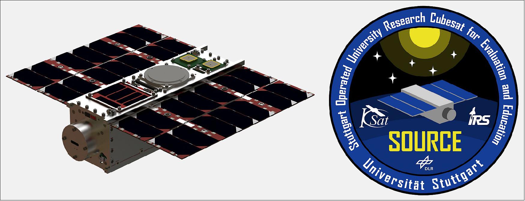
The main monochromatic camera mounted on SOURCE ("MeSHCam") is part of a future IRS mission and will be flight tested, functioning as an earth observation camera as well as a star tracker for attitude control. There is also a smaller colour camera called PRIma (PR-Imager). Besides the space testing of these components there are multiple scientific payloads by the IRS on board SOURCE. Two FIPEX Sensors will measure the level of atomic oxygen in altitudes below 200 km. Heat flux sensors combined with pressure sensors will study the environment of the CubeSat just before reentry.
Multiple additional technology demonstrators are provided as payload for SOURCE by IRAS (Integrated Research Platform for Affordable Satellites), a corporation of industry and research groups to launch a development platform for satellites and new technologies. This includes solar panels, a composite sandwich structure and other sensors. Further payloads are provided by the German Aerospace Center (DLR).
Mission objectives 2)
• Education of the next generation of space engineers
- Student team (KSat e.V.) with Ph.D. supervisors (IRS)
- Lecture, bachelor and master theses, volunteer work
- > 80 active members, >200 in total
• Investigation of re-entry events for clean space
- In-situ and optical measurements (Meteors)
- Improvements for numerical tools (PICLas)
• Technology demonstration
- Automotive parts in space
- Integrated-circuit sandwich structures.
The SOURCE collaboration consists of the following partner organisations: IRS (Institute for Space Systems, University of Stuttgart), DLR (German Aerospace Center), Airbus (Airbus Defence and Space), Fraunhofer IPA (Fraunhofer Institute for Manufacturing Engineering and Automation), STI (Space Tech GmbH), Azur Space (Azur Space Solar Power GmbH), and IRAS (Integrated Research Platform for Affordable Satellites). The SOURCE project is carried out with the support of the Education Office of the European Space Agency (ESA), under the educational Fly your Satellite! Programme. KSat e. V. Stuttgart (small satellite student society at the University of Stuttgart) is a non-profit organization founded in the spring of 2014. The more than 130 members are students of all semesters, mostly enrolled in aerospace engineering. The association is open to students of all disciplines.
Development Status
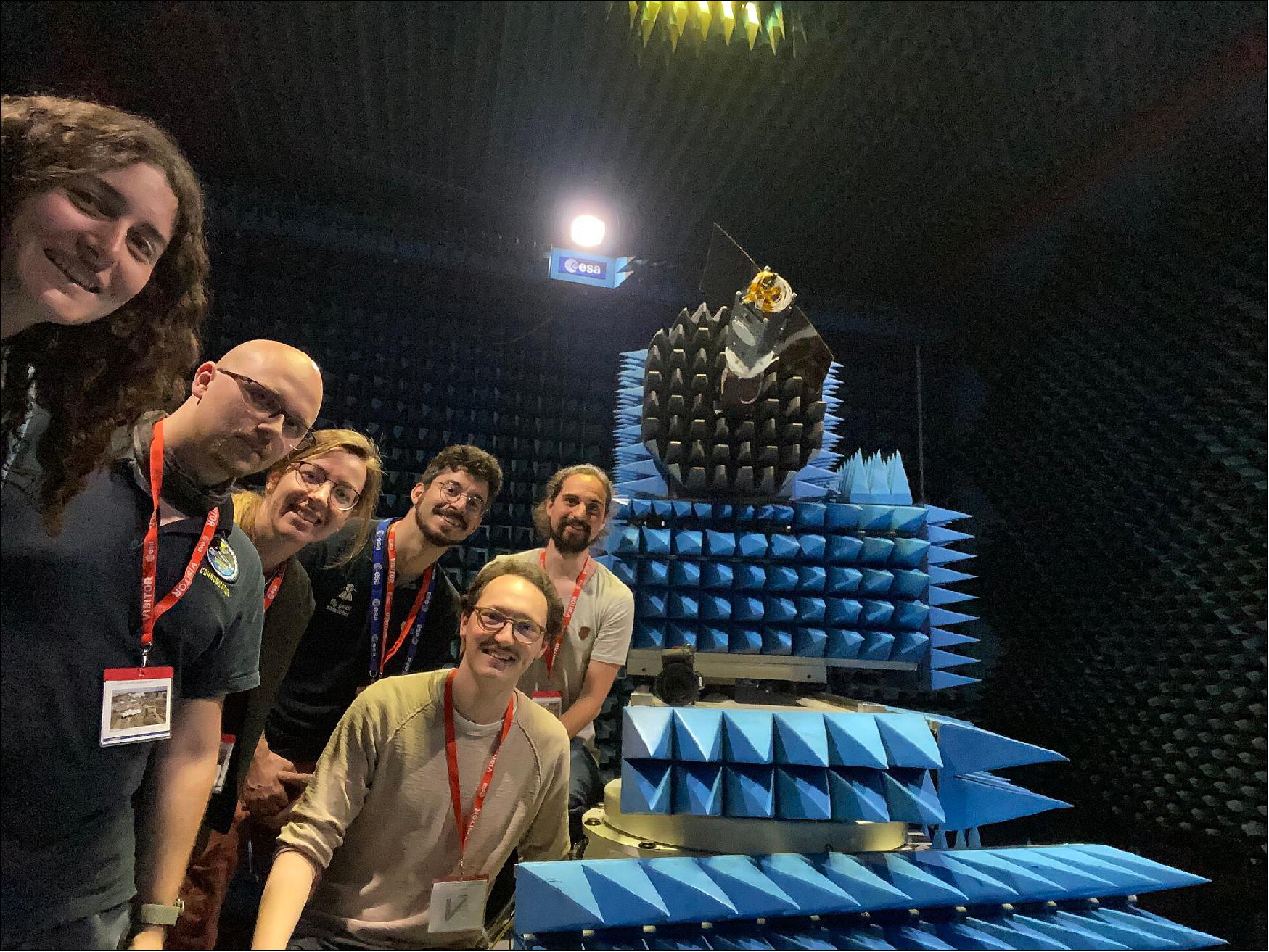
• June 14, 2022: From 31 May to 2 June 2022, four students from the University of Stuttgart’s SOURCE team embedded themselves within the CATR (Compact Antenna Test Range) at ESTEC in the Netherlands. As a Fly Your Satellite! third edition team, they have been busy building and testing their three-unit CubeSat prior to launch into space. 3)
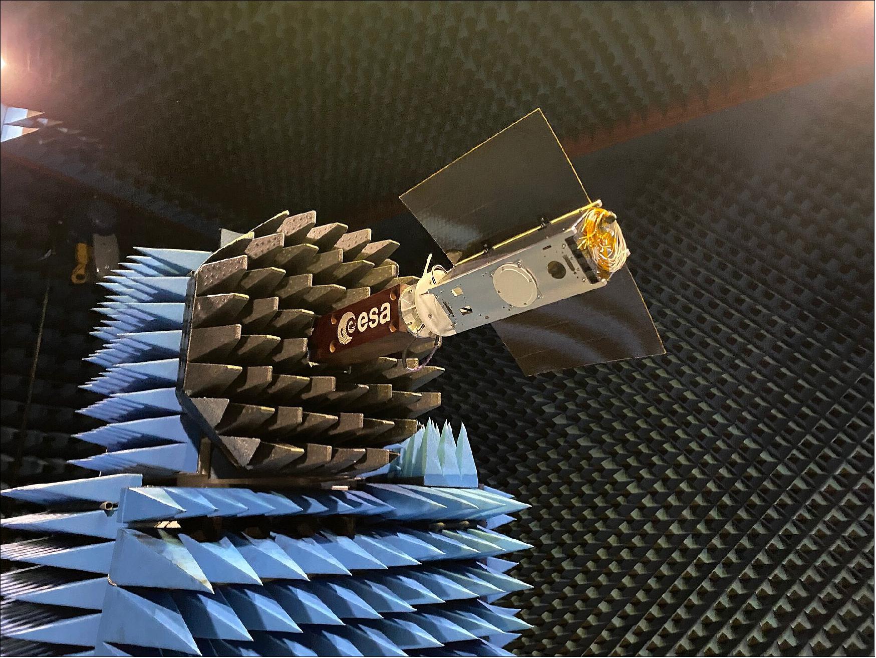
- The students brought with them a “look-alike” satellite mock-up, closely matching their real design’s external dimensions. Onto this model they carefully installed two antennas that will eventually be used in flight for radio communication between SOURCE and its ground station. Their goal: measure the performance of the antennas when operating together, as they are intended to do in flight, to relay the satellite’s data back to Earth; in effect, testing their satellite’s “voice”!
- Said a participating student, “During the week we had many opportunities to discuss details of our project with experts and to see many interesting things on site. Many thanks to everybody who participated and ESA’s Fly Your Satellite!”
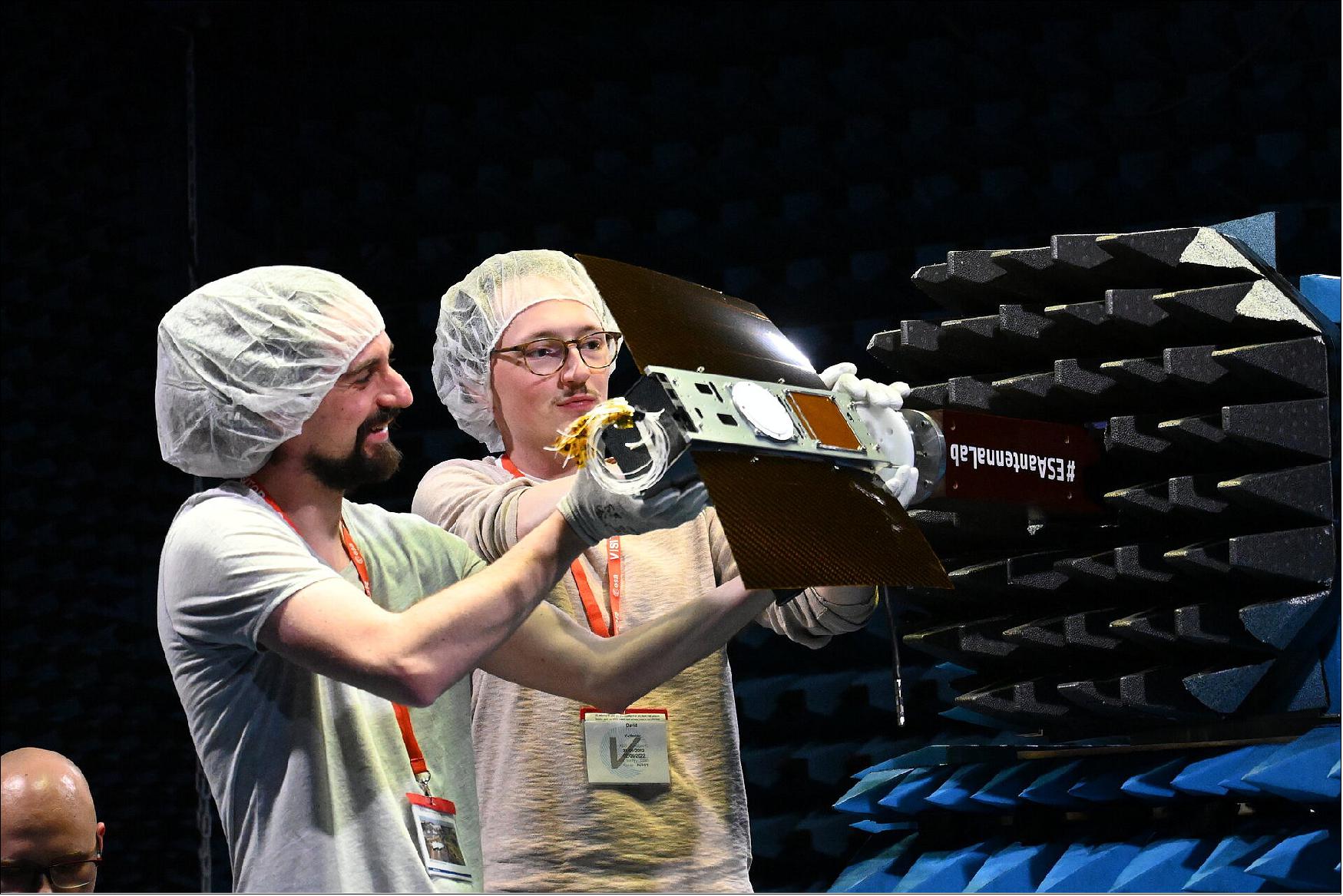
- The students measured their hardware’s performance in a number of different configurations in the CATR, allowing them to collect valuable data. They will now analyse this in order to determine whether the design they have developed will allow for successful communication at all stages of SOURCE’s mission in orbit.
- “The week at ESTEC was a great opportunity to use such a professional test facility for antenna measurements,” explained a SOURCE student. “The gained data will help us to verify our communication system and data and link budgets.”
• In July 2021 SOURCE passed the CDR (Critical Design Review) after a very thorough and detailed technical examination by ESA experts. The team is now busy building and testing prototypes in preparation for the manufacturing of the actual flight hardware. The flight software is being developed and tested in parallel. 4)
- The SOURCE students have been supported by ESA experts throughout their CDR processes. The Fly Your Satellite! programme emphasises knowledge transfer as part of its educational objective, and as such, students have frequent, direct exchanges with ESA experts, helping to enhance satellite designs and boost the chances of a mission’s success.
- The SOURCE team now has a green light to proceed to the next phase of their journey. They will continue with subsystems development and testing in preparation for the Manufacturing Readiness Review. This will lead to integration of the CubeSat flight model, followed by testing in ambient conditions to demonstrate its functionality. Every step takes the team closer to their dream of launching a satellite into orbit!
• Phase B of the project has been completed successfully in March 2019 with the PDR (Preliminary Design Review). Since March 2020 the project is carried out with the support of the Education Office of the European Space Agency, under the educational Fly your Satellite! programme. After successfully participating in the Selection Workshop in December 2019 SOURCE was selected to participate in the third edition of the programme together with two other student satellite projects. This means that the team is now supported by ESA experts during development and testing of the satellite, culminating in a launch to orbit organised by ESA. This is currently planned for early 2023.
Launch
A launch of the SOURCE 3U CubeSat is expected in 2023.
Sensor Complement
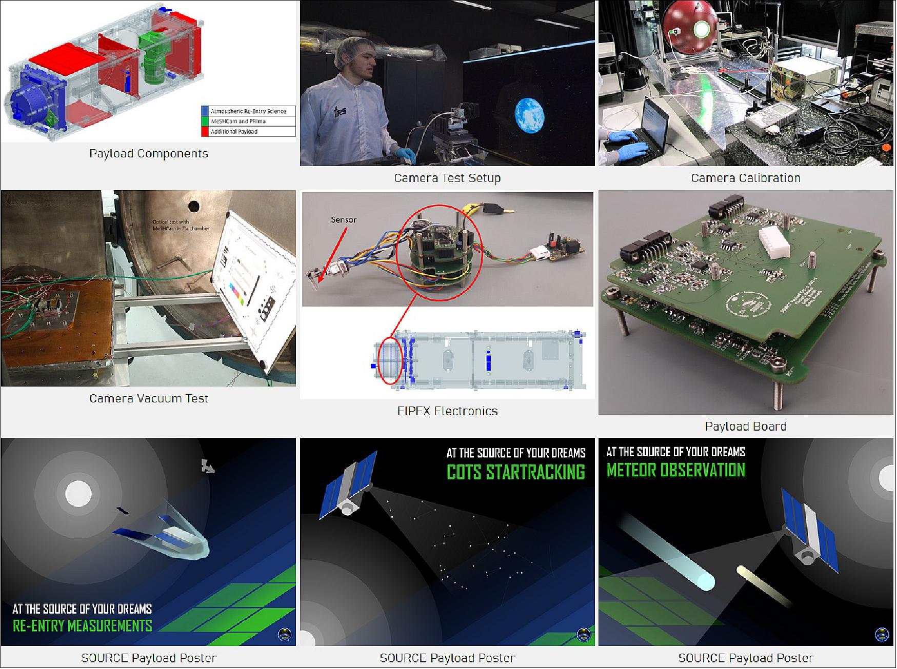
The SOURCE payload can be separated into three groups: the camera system, the atmospheric- and re-entry sensors and the IRAS components (see Ref. 1).
The goal of the atmospheric sensors is to verify and improve simulations of re-entry scenarios with the software PICLas. To achieve this, several sensors are placed on the satellite which carry out measurements over the duration of the mission with a focus on the re-entry of the CubeSat. These sensors consist of two different types of heat flux density sensors, photodiodes, pressure sensors and FIPEX sensors for measuring oxygen developed by the IRS.
The camera system will demonstrate a star- and horizon tracker for attitude determination, as well as observe meteors to improve the understanding of the beginning of the solar system and test the system for future missions. Since the satellite will operate above the atmosphere, the light of meteors is not absorbed and more faint meteors can be observed. The second camera, called PRIma (PR-Imager), will be used for Earth observation and to test the camera in space. The cameras consist of “commercial off the shelf” (COTS) parts to verify these parts for operation in a spaceflight environment.
As the third payload component, the satellite will carry multiple technologies developed by the IRAS project. The goal of the IRAS-project is to reduce manufacturing costs for satellites by using commercial components. The payload of the IRAS project on SOURCE consists of an efficient type of solar cell by AzurSpace, a smart heater which self regulates the heat output and a multifunctional sandwich structure with built in radiometry sensors, inertial measurement units (IMUs) and strain gauges.
Spacecraft
Structural Design and Thermal Management: The structural design team is in charge of the physical layout and the thermal management of the satellite. It is this team’s job to fit the components of all subsystems into the given dimensions and to make sure they stay within their operating temperatures. It also designs the deployment mechanisms for the solar panels.
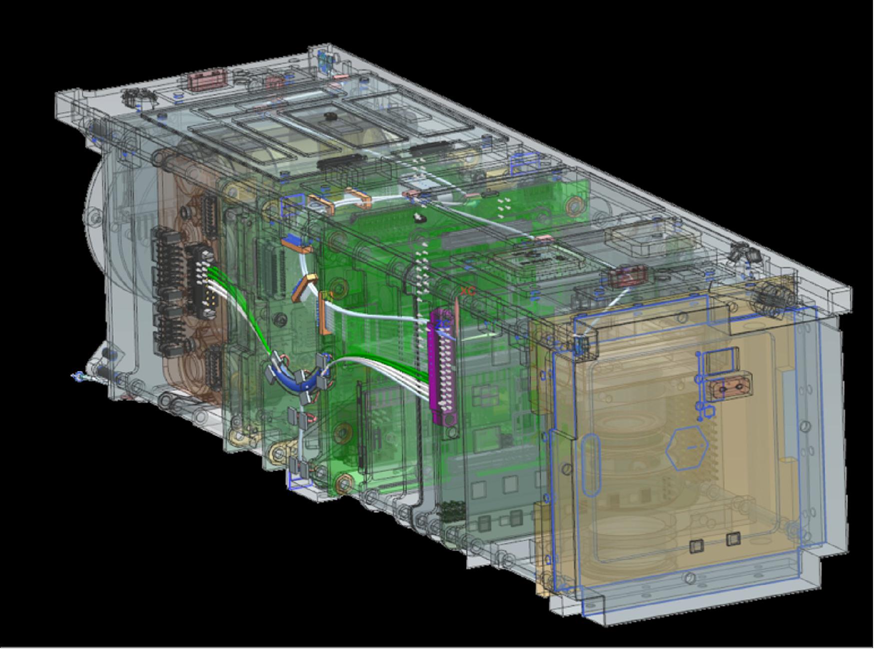
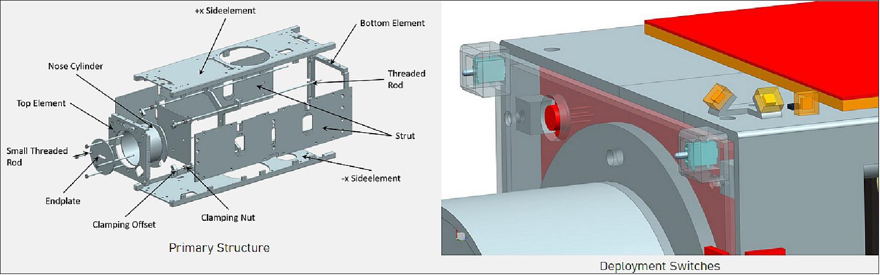
The primary structure functions as the backbone of the satellite and houses all experiments as well as their supply systems. Each printed circuit board is mounted on four threaded rods secured by a clamping mechanism. Afterwards solar panels, antennas and experiments are attached to the outer surface. All electrical components are monitored by thermal sensors and kept in their respective operational thermal range with heaters. FEM and thermal simulations analyse the behaviour of the satellite during launch and on orbit. Currently, the primary structure and ground support equipment are prepared for production. An assembly and integration plan is being prepared as well. After assembly and integration of the prototype shaker tests to simulate the launch loads will be carried out.
Another task of the structural team is the design of the deployment switches. These are released when the satellite is ejected from the CubeSat deployer and then activate the satellite.
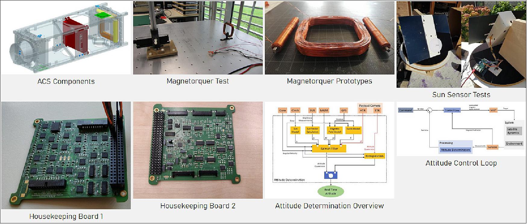
Attitude Control System: The Attitude Control System (ACS) is in charge of the pointing of the satellite. After the ejection out of the rocket it needs to stabilize the satellite. During the main mission the solar panels need to be reliably pointed towards the sun and occasionally the cameras towards the earth. To achieve this and to provide context to payload measurements, a precise determination of the attitude must be possible on board.
SOURCE uses magnetorquers to adjust its attitude. These coils create a magnetic field which aligns itself with Earth's magnetic field. This process introduces a turning moment which can be used to control the satellite. With only magnetorquers it is impossible to create moments around the magnetic field vector. This means that the satellite can only be controlled in two axes at any given time. However, as the satellite flies around the earth it travels through different regions of the magnetic field, allowing for full three-axis control. The magnetorquers on SOURCE are self-built and fully developed by students. Two are designed as cylindrical coils with ferrite cores, the third as a flat square with no core. Prototypes of the design have been successfully tested with excellent performance.
To determine the satellites position and attitude, sun sensors, magnetometers, GPS and gyroscopes are used. The sensors measurements are compared to a sun model and a magnetic field model. As Earth's magnetic field changes depending on the satellites position, the GPS is used to gain accurate position information. All the sensors measurements are combined into a 3-axis attitude determination in a Kalman filter.
Besides these for CubeSats typical sensors the earth observation camera will be tested as a sensor for attitude determination. It will take pictures of the stars which will then be compared to a constellation map. The concept of star trackers has been used on many satellites and is nothing new. However, using a commercial earth observation camera is a novel development. This is a technology demonstration which means that the system as a whole cannot be dependent on the camera as a sensor. If it works it promises much more accurate attitude information than the other sensors can provide.
The sensors, readout and control electronics for the ACS are located on the two housekeeping boards. Prototypes and qualification models of these PCBs are currently being built and tested.
The attitude control software is being developed in a Matlab-Simulink based simulation environment. The control laws for detumbling, sun tracking and camera pointing are all tested and shown to be working, but will need to be further optimised when the satellite design parameters are fully consolidated and the target orbit is fixed. The simulation also includes the sun sensor, guidance and attitude determination algorithms.
Onboard Data Handling: The subsystem on-board and data handling is the central unit responsible for controlling and monitoring the CubeSat. Commands are distributed, the status of the entire satellite is monitored and events are logged. The on-board computer used to satisfy the requirements essentially consists of a microcontroller, different memory units and various interfaces for the communication with other subsystems.
The basic tasks which are assigned to the OBDH system are:
- the storage of housekeeping data
- the storage and processing of payload data
- the transition between the satellite modes
- the execution of the attitude control algorithm
- the detection and correction of device malfunctions
- the execution of telecommands
- the preparation of data for the transmission to the ground station.
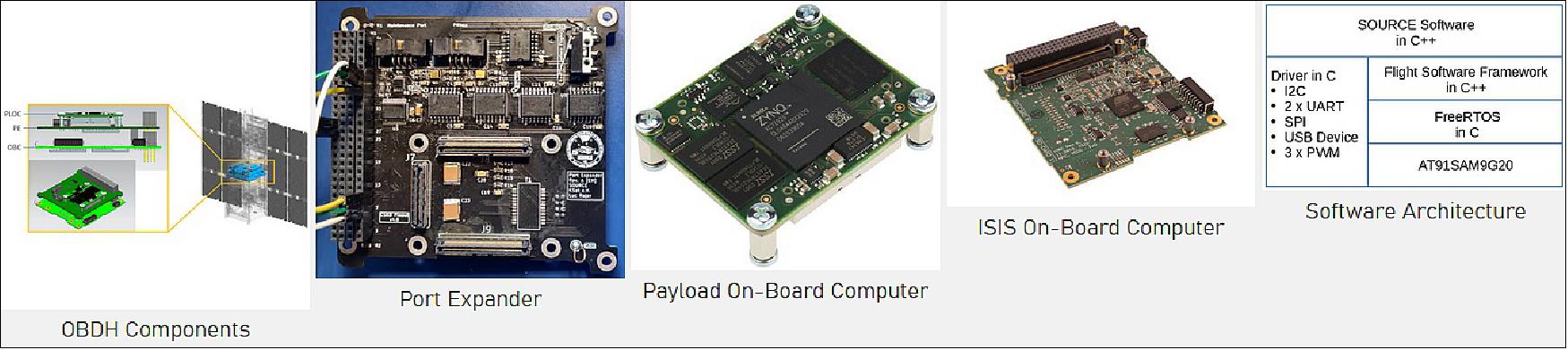
Hardware: As on-board computer with sufficient computing power and memory capacity for the reliable execution of all the tasks the iOBC (ISIS On-Board Computer) was selected in Phase A.
- 400 MHz ARM9 processor
- Volatile memory: 32 MB SDRAM
- Mass data storage: 2 x 2 GB SD cards
- Code storage: 1 MB NOR Flash
- Critical data storage: 256 kB FRAM
The "Port Expander" is a circuit board developed by us which sits on the on-board computer. Its jobs are to perform conversion of some signals, route connections relevant to the on-board computer, increase the amount of ports available to us, and connect to the payload on-board computer. In addition, the Port Expander connects the on-board computer to the CubeSat-Kitbus, which is the main bus of the satellite, connecting all circuit boards.
When signals are sent between different components, we use various protocols and connectors. Some of these include RS485, on which we use the unified space data link protocol (which uses "frames" to transport data "packages"), and the serial peripheral interface (SPI). SPI is a very important interface for us, as we connect over 30 devices to the on-board computer using this bus. In addition, we use USB and Gigabit Ethernet adapters to connect the on-board computer to the payload on-board computer via the Port Expander.
Software: Figure 10, titled "Software Architecture", shows the fundamental structure of the on-board software for SOURCE. The AT91SAM9G20 as execution platform represents the physical layer in the architecture upon which the real-time operating system FreeRTOS is implemented. For the implementation of FreeRTOS, the microprocessor must only provide a timer that generates an interrupt each millisecond. FreeRTOS allows the separation of a program in several processes by managing the assignment of processor internal resources like processor time and memory to the various processes. In contrast to standard operating systems, a process in a real-time operating system (RTOS) with lower priority can never be executed before a process with higher priority. This is one of the crucial features of an RTOS and a prerequisite for ensuring the real-time requirements of the software.
Furthermore, the software is based on a Flight Software Framework (FSFW) developed at the Institute of Space Systems (IRS) which is already being used successfully for the software of the small satellite Flying Laptop. The FSFW provides several building blocks and templates for software components in the form of abstract classes promising a reduction in development time and an increase in reliability for new flight software. As an example, the FSFW contains a sub-framework facilitating the programming of PUS services. PUS stands for Packet Utilization Standard and is a protocol developed by ESA. This standard specifies a set of mission-independent services for satellite operation and defines the associated packet structure resulting in communication compatibility between several ground and on-board systems. For implementing the Software we use the programming language C++.
For software prototyping, the AT91SAM9G20-EK development board is used which is based on the same microprocessor as the iOBC. Currently, the software consists of FreeRTOS, the FSFW and several PUS services programmed during phase C1. Furthermore, the lwIP stack was implemented and the Ethernet interface of the AT91SAM9G20-EK was configured which allows uncomplicated testing of the PUS services. For the testing, a python script was written that automatically sends different telecommands and verifies their processing through the returned data.
In phase C2, the integration of all the device drivers into the software is planned. This includes the programming of the interface drivers as well as implementing device-specific components such as communication protocols or troubleshooting measures.
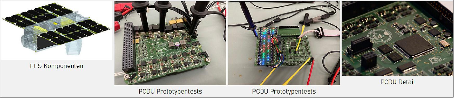
EPS (Electrical Power System): The main task of an (EPS) is power generation, energy storage and the distribution of power to other subsystems. It also has to provide power to deploy the solar arrays and activate the satellite. The EPS of SOURCE required some more advanced features and functionalities compared to a normal CubeSat mission. Therefore, the solar array configuration and PCDU (Power Conditioning and Distribution Unit) is self-developed.
A total of 56 solar cells provide up to 32 W under ideal conditions, which can be stored in a 75 Wh space qualified lithium ion battery from Gomspace (BPX). To maximise the power output of the solar cells, Maximum Power Point Tracking (MPPT) is performed by the PCDU. This is controlled by a radiation hardened microcontroller (Vorago 10820). The microcontroller also controls the switching between the various CubeSat modes (as commanded by the OBC) and the individual power output channels. There are 32 switchable channels which control every subsystem and component of the CubeSat. Additionally, the subsystems power consumption is monitored for over-currents. The health of the OBC is monitored as well and can be rebooted in case of a failure. The PCDU can also be directly commanded via the communication subsystem from the ground with so called High Priority Commands that can reset either the communication subsystem, the OBC or the entire satellite. The EPS is crucial for mission success so redundancy and fail-safe components are implemented as far as possible and a mix of COTS and space qualified components is used.
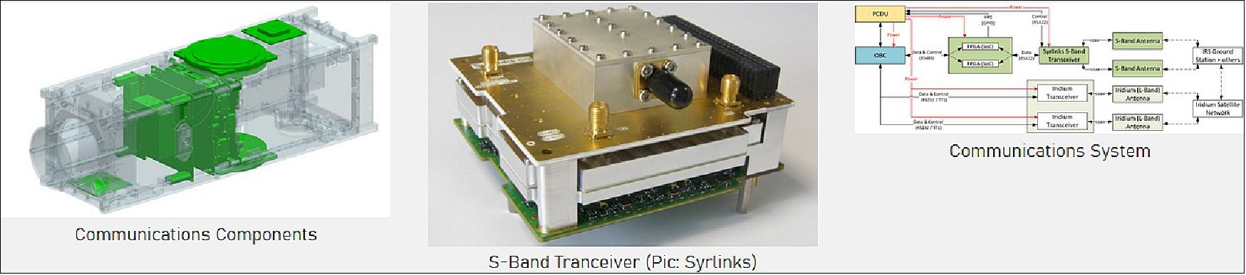
Communications: The communications subsystem has three tasks:
- Receive commands to control the satellite
- Send status information to the ground station
- Transmit payload data.
The first two are most critical for the mission, since an erroneous command can easily let the satellite malfunction. Payload data, on the other hand, focuses more on the achievable data rate. Up to 1 Mbit/s is planned.
The direct communication between the IRS ground station and SOURCE is conducted in the S-band (2 – 2.4 GHz). This can also be used to communicate with partner ground stations worldwide. S-band technology is more typical for larger satellites but is now finding its way into CubeSats. Additionally, SOURCE can communicate to commercial satellite constellations in the L-band (1.6 GHz). This allows SOURCE to transmit data regardless of its current position. Such abilities are rare for CubeSats.
The satellite receives signals through two patch antennas. This antenna type can receive from any direction. The signals are then processed by a transceiver, which converts them into computer-readable data. The reverse path, towards the ground station, works exactly the same. This defines the transceiver: it combines a receiver and a transmitter. The currently planned transceiver is supplied by Syrlinks.
All transmitted data is packed into protocols for each layer. Additionally, certain coding algorithms are employed to increase the reliability of the transmission. With these the system can detect and correct errors in any received data. SOURCE uses international standards as defined by the CCSDS (Consultative Committee for Space Data Systems). FPGAs provide the computing power to code or decode messages.
The eventual reentry – which will destroy the satellite – may happen over an area without ground stations, for example the Pacific Ocean. To preserve the important atmospheric data that is gathered during this phase, a secondary communications system is installed. It communicates to the commercial Iridium satellite constellation in the L-band (1.6 GHz). Iridium operates a constellation of 66 satellites; primarily for satellite telephones and internet. The transceiver on SOURCE was, originally, meant for regular satellite telephones. Through this network short messages, similar to SMS can be sent.
Ground Segment
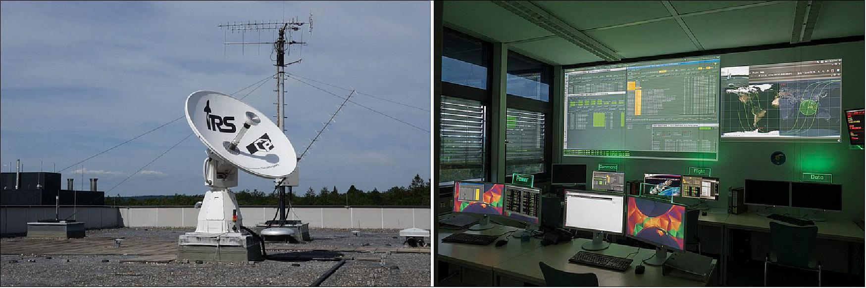
The Operations and Ground Systems (OPS&GRND) subsystem deals with the planned operation of the satellite and the infrastructure required to operate the ground segment - which is the counterpart to the space segment (the satellite). The ground segment includes the ground station, the Mission Control System, the Mission Planning Tool and the Flight Dynamics Tool. SOURCE will use the ground station of the IRS, which is currently operating and used for the satellite "Flying Laptop".
However, this will require re-engineering the existing interface software of the ground station so that it can also be used for SOURCE. The mission planning tool is currently being developed and a similar infrastructure as in the other ongoing satellite projects of the institute is used as Mission Control System (MCS). The flight dynamics tool is used to evaluate the navigation data and provides essential data for mission planning, e.g. at what time SOURCE flies over which coordinates. In a further step, the task of this subsystem is to automate as much work as possible in order to simplify the future operation of the satellite.
Furthermore, OPS&GRND deals with the creation of the user manual of the space segment, as well as the creation of the satellite reference database (a kind of dictionary) to translate between satellite and ground segment. In addition, OPS&GRND supports the creation of procedures and their testing, as well as the appropriate adaptation to operational constraints. In preparation for operations, various scenarios must be simulated and a schedule created to ensure safe operation of the satellite and thus the success of the mission. The corresponding training of the initial mission critical Launch and Early Orbit Phase will be performed in close cooperation with the subsystem Testbed.
Testbed: The two main goals of the Testbed subsystem are to provide a framework for integrated testing of the satellite system and training the operations team. It also designs a simulator for testing the satellite's software.
A very important part is the so-called “FlatSat”. This is an assembly of almost the whole satellite system in the cleanroom. Every component is tested by its respective subsystem, but the FlatSat allows to test the satellite as a whole. This is especially important to avoid conflicts on the satellite bus. Due to the assembly of the FlatSat being “flat” on a desk, testing different aspects of individual components is made simpler. This also allows easy replacement of components.
Additionally, a simulation is planned of different satellite components in orbit. To achieve this goal, different components (battery, solar-cells, gyroscope sensors, etc.) will be programmed as simple models. Those models will generate the data, appropriate for the simulated scenario. The data will be routed to the On-Board-Computer (OBC). This allows to test edge-cases, like testing a component outside its specifications or component failures. The design also allows to generate data, as if the components were in orbit, while the hardware is situated in the cleanroom. To connect the OBC on the FlatSat with the simulator, a special interface for the satellite bus must be developed. For the interface to work correctly, different aspects must be considered, one of the most important being the latency between call and response.
Besides being an assembly to do all the necessary tests of the complete satellite-system, the “Testbed” (as a structure of the FlatSat connected to the simulator) provides the possibility to emulate different scenarios. Those can be used, to train planned procedures by the Operations-Team, or to test the attitude-control algorithm of the ACS-Team, to name just two.
References
1) ”SOURCE Stuttgart Operated University Research CubeSat for Evaluation and Education,” KSat, 2022, URL: https://www.ksat-stuttgart.de/en/our-projects/source/
2) Daniel Galla, Sabine Klinkner, Georg Herdrich, Clemens Kaiser, Hendrik Kuhm, Hendrik Fischer, ”A CubeSat for demise investigation – SOURCE’s approach for a better understanding of satellite re-entries,” 2020, URL: https://conference.sdo.esoc.esa.int/proceedings/isdrw05/paper/19/isdrw05-paper19.pdf
3) ”SOURCE team test their CubeSat’s “voice” during Fly Your Satellite! antenna test campaign,” ESA Education, 14 June 2022, URL: https://www.esa.int/Education/CubeSats_-_Fly_Your_Satellite/SOURCE_team_test_their_CubeSat_s_voice_during_Fly_Your_Satellite!_antenna_test_campaign
4) ”SOURCE CubeSat team passes Critical Design Review,” ESA Education, 23 July 2021, URL: https://www.esa.int/Education/CubeSats_-_Fly_Your_Satellite/SOURCE_CubeSat_team_passes_Critical_Design_Review
The information compiled and edited in this article was provided by Herbert J. Kramer from his documentation of: ”Observation of the Earth and Its Environment: Survey of Missions and Sensors” (Springer Verlag) as well as many other sources after the publication of the 4th edition in 2002. Comments and corrections to this article are always welcome for further updates (eoportal@symbios.space).
Development Launch Sensor Complement Spacecraft Ground Segment References Back to top