STEREO (Solar-Terrestrial Relations Observatory)
Non-EO
NASA
Space Weather
Quick facts
Overview
| Mission type | Non-EO |
| Agency | NASA |
| Launch date | 26 Oct 2006 |
STEREO (Solar-Terrestrial Relations Observatory)
Spacecraft Launch Mission Status Sensor Complement Ground Segment References
The STEREO mission is a strategic element of NASA's Sun-Earth Connection program, a multi-institutional and international collaboration involving participants from France, Germany, the Netherlands, Belgium, Switzerland, the United States, and the United Kingdom. STEREO is the third mission of NASA's Solar Terrestrial Probes program. The overall objective is to increase the understanding of the origin and consequences of CMEs (Coronal Mass Ejections). 1) 2) 3) 4) 5) 6) 7)
Over a period of two to three decades, solar physicists have come to realize that the extremely energetic solar storms known as CMEs are the form of solar activity felt most forcefully at Earth. CMEs impacting Earth’s environment are the primary cause of major geomagnetic storms, and they are associated with nearly all of the largest solar proton events, which are streams of protons ejected from the Sun with so much energy that they can pose a significant radiation hazard to men and machines in space. The growth in society’s reliance on technology has led to an increased vulnerability to impacts from the space environment and, hence, to an importance in understanding the multifaceted influence of the Sun and CMEs on Earth. 8)
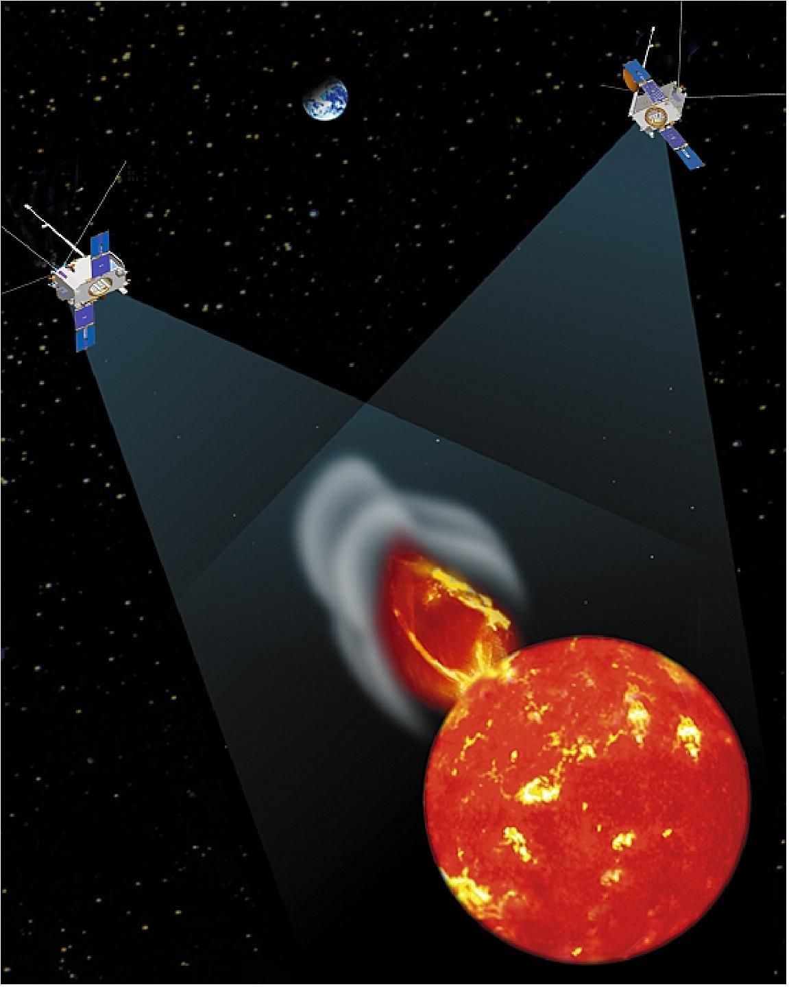
The mission consists of two nearly identical spacecraft in heliocentric elliptical orbit in the ecliptic plane at approximately 1 AU from the sun: one drifting ahead of the Earth and one behind. Simultaneous measurements are obtained by the satellites instruments at gradually increasing separations over the course of the two-year mission. The STEREO mission observation capabilities are:
• First stereo viewing of Sun from out-of-Earth-orbit vantage points
• First imaging and tracking of space disturbances from Sun to Earth
• First continuous determination of interplanetary shock positions by radio triangulation
• First simultaneous imaging of solar activity with in-situ measurement of energetic particles at 1 AU.
Spacecraft
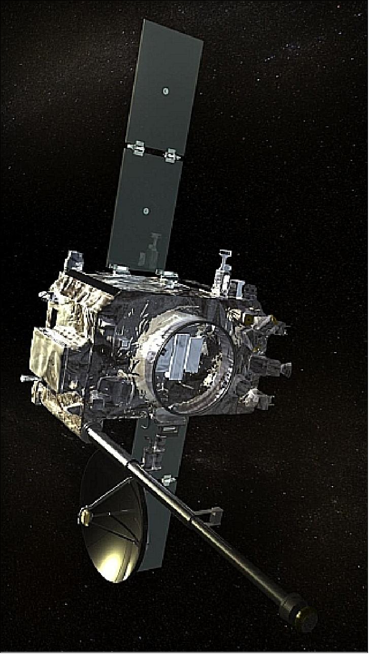
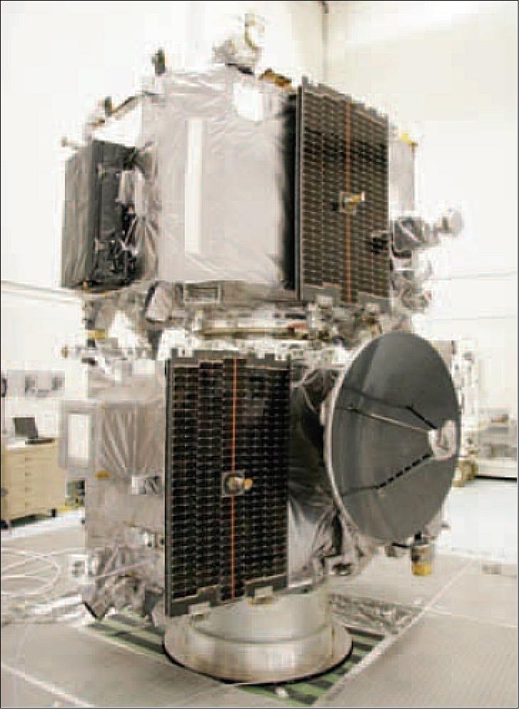
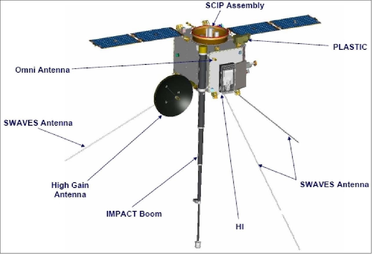
The STEREO S/C bus consists of a box-like structure of size 2.03 m x 1.22 m x 1.14 m (deployed length of 6.47 m). The S/C is built and integrated by JHU/APL with NASA/GSFC procuring the instruments and launch vehicle. The satellite is three-axis stabilized. Attitude sensing is provided by a star camera, two DSAD (Digital Solar Attitude Detector) systems, an IMU (Inertial Management Unit), and a pointing error signal generated by the instrument guide telescope. Actuation is provided by four reaction wheels and 12 thrusters. A S/C pointing accuracy of 7 arcsec (control) and 0.1 arcsec (knowledge) is provided. Each S/C utilizes four sets of solar arrays, each of which experiences a two stage deployment on orbit. The deployed solar arrays generate an average power of 475 W (EOL). A Super NiCd battery of 21 Ah is used for eclipse phase operations. 9) 10) 11) 12) 13)
The bus is designed around the IEM (Integrated Electronics Module) and the PSE (Power System Electronics) unit. The IEM contains the RF uplink and downlink cards, power converter cards, and an AIE (Attitude Interface Electronics) card. The cards within the IEM communicate over a PCI (Parallel Communication Interface). The Power System Electronics unit contains relays and control circuitry for the S/C power system. A MIL-STD-1553 bus architecture is used for on-board command and telemetry transmission between the IEM, the instruments, attitude sensors, and the PSE. Each spacecraft has a mass of about 620 kg (wet) and a design life of two years. 14)
G&C (Guidance and Control) system: The Sun-pointed imaging instruments require very tight pointing of their boresights and small jitter with a significantly relaxed roll requirement. The two coronagraphs, COR1 and COR2, along with the EUVI and GT (Guide Telescope) are mounted on an optical bench in the middle of the spacecraft, and together they compose the SCIP (Sun-Centered Imaging Package). The three Sun-pointing instruments on SCIP (see also Figure 42) require very tight pointing of their boresights toward the center of the Sun to observe CME initiation and propagation and a very stable platform, i.e., minimal jitter, to prevent image smear and enable 3-D image reconstruction. 15)
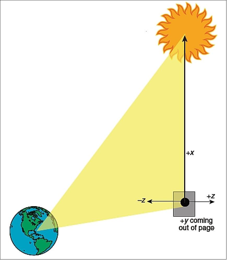
Pointing requirements: The nominal STEREO mission attitude keeps the spacecraft +x axis centered on the Sun with the Earth in the x–z plane on the –z side of the spacecraft (Figure 3). This attitude is maintained at all times except during instrument- and antenna-calibration maneuvers and during propulsive maneuvers (orbit adjustments that occurred in the phasing orbits and the dumps of accumulated angular momentum that occur routinely on both spacecraft throughout the mission).
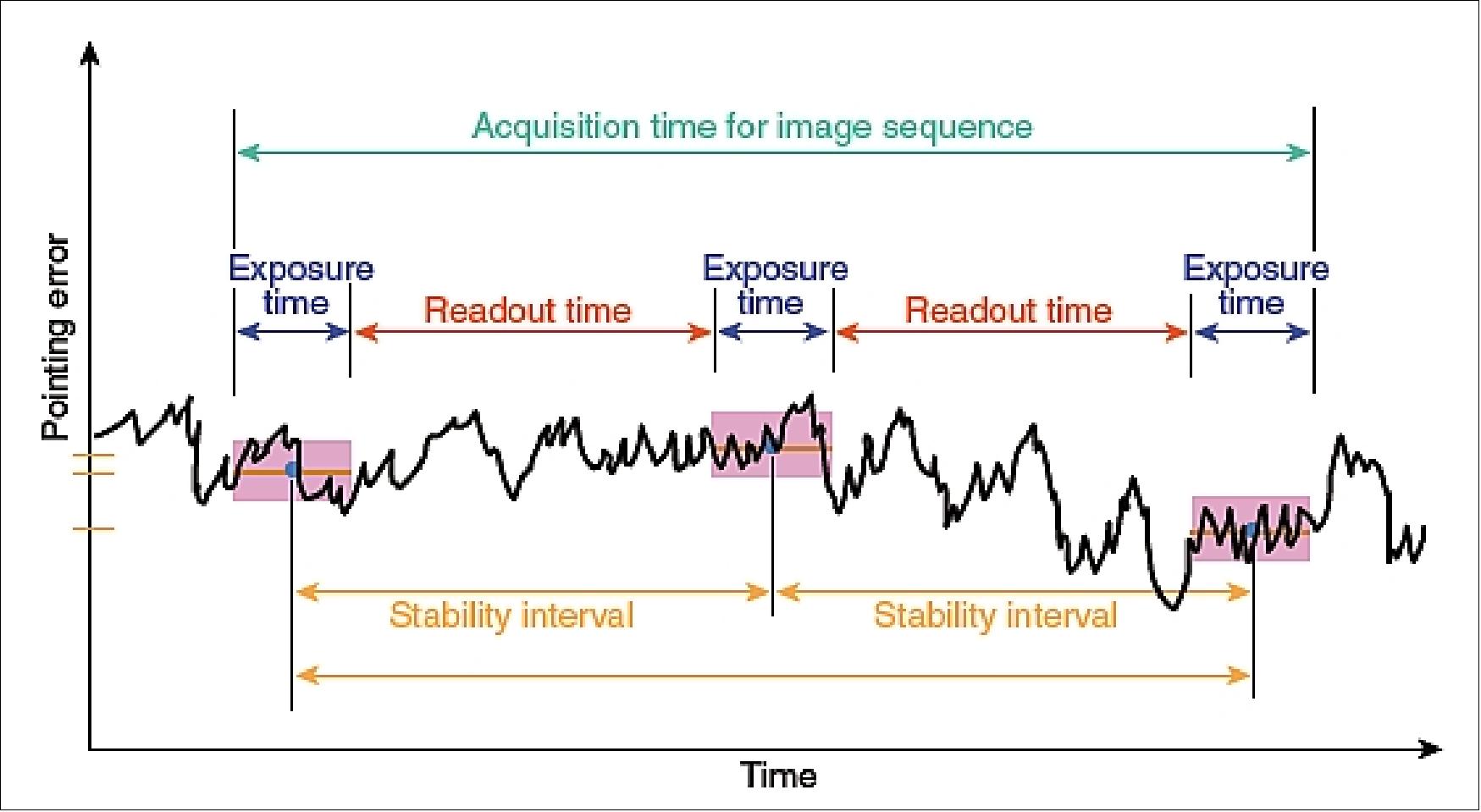
The fine Sun-pointing requirements are driven by the SECCHI instruments, specifically those mounted on the SCIP, to provide clear images requirements refer to three terms, accuracy, jitter, and and to enable image-to-image correlation (Figure 4).
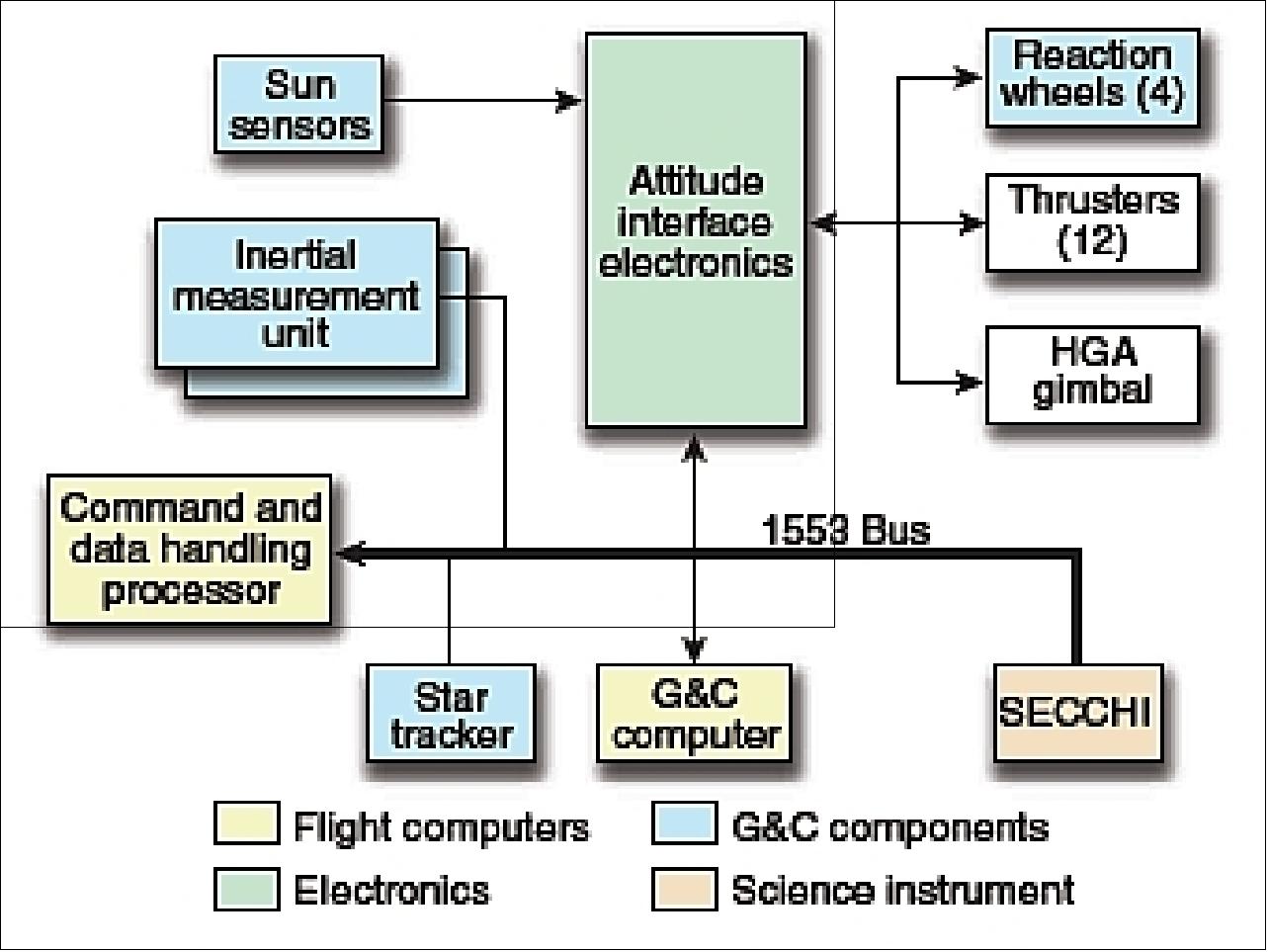
G&C system: Each of the nearly identical STEREO spacecraft is three-axis-stabilized with fixed solar arrays for power generation as well as a steerable HGA (High Gain Antenna) for heliocentric orbit communications. A complement of Sun sensors, a ST (Star Tracker), redundant IMUs (Inertial Measurement Units), the GT, reaction wheel assemblies, and a monopropellant hydrazine propulsion system are used by the G&C system to keep the two STEREO spacecraft three-axis-stabilized. The system is selectively redundant.
All sensor data and actuator commands are fed over a MIL-STD-1553B data bus to/from the onboard flight computers (Figure 5). The G&C algorithms run in the flight computer at 50 Hz and determine spacecraft state and compute errors, and issue commands to the actuators (wheels and thrusters) to maintain control.
The single, nonredundant ST on each spacecraft provides fine, three-axis inertial pointing knowledge during all phases of the mission at 10 Hz. After initial GT acquisition, the ST is primarily used to provide roll knowledge. A single IMU (the second is a cold spare) contains gyros and accelerometers that provide three-axis, incremental angle, and linear-velocity (only used when firing thrusters) measurements. IMU data (100 Hz) are provided to the flight algorithms, which use the last valid measurements in the control loop to propagate the inertial attitude knowledge between ST updates.
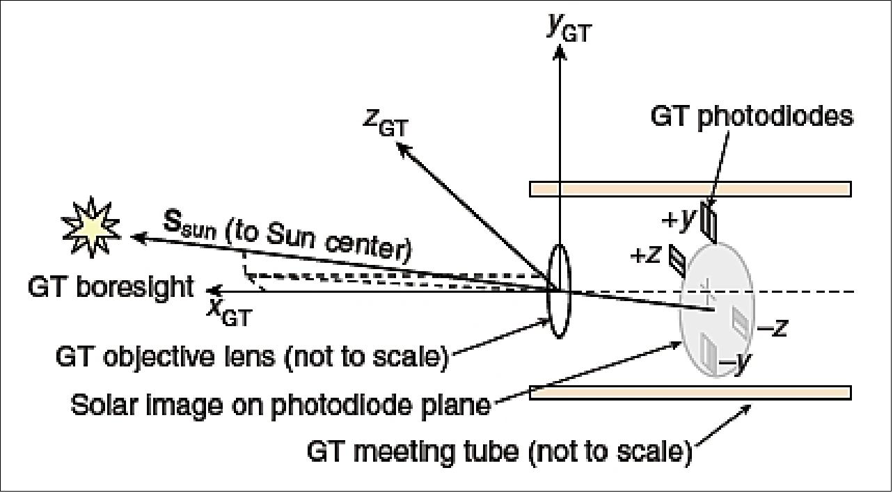
The GT, part of the SCIP instrument suite, provides the fine-pointing error signal. Its axes are nominally aligned with the spacecraft axes (Figure 6). It reports to the G&C (at 250 Hz) the y and z components of the apparent unit vector to the Sun as measured in the GT coordinate system (the assumption being that the x-axis component is approximately one). It has an acquisition range of slightly >15 arcmin and a fine-pointing range of approximately 70 arcsec. The GT is able to report the off-Sun pointing error to an accuracy of 0.4 arcsec, 3σ, in each axis for a single measurement; averaging can further reduce the error. Five 250-Hz samples are passed to the G&C flight computer for processing every 20 ms (50 Hz).
Actuators: Four reaction wheel assemblies, arranged in a typical, pyramidal configuration, are the primary actuators for each STEREO spacecraft. The wheels, models RSI 12-75/607 manufactured by Rockwell-Collins, Deutschland GmbH (formerly Teldix), have a torque capability of 75 mNm and an angular momentum storage capacity of 12 Nms. All four wheels are operated simultaneously to maintain three-axis attitude control while providing an extra degree of freedom to redistribute angular momentum among the wheels. The wheels were carefully selected and placed on each spacecraft in an effort to minimize disturbances at the SCIP induced by static and dynamic wheel imbalances.
Dumping of accumulated angular momentum due to solar-pressure torques is accomplished with a monopropellant hydrazine blowdown propulsion system. Twelve thrusters, each nominally providing 4.4 N of force, are arranged in three sets of four with any set of four thrusters providing three-axis attitude control torque capability (via double-canting of each thruster) in addition to the nominal force in the particular direction. During a momentum dump, the thrusters are used to maintain attitude control while the wheels are torqued to their commanded momentum states.
RF communications: The onboard solid-state recorder has a capacity of 7.5 Gbit. RF communications are provided in X-band. The downlink data rate is variable up to about 720 kbit/s. The downlink data modulation is bi-phase shift keyed (BPSK). The uplink modulation is phase modulated (PM). Mission operations are conducted by JHU/APL at the MOC (Mission Operations Center) in conjunction with each POC (Payload Operations Center) for instrument operations (located at NRL, UMN, UCB, CalTech, and UNH).
In addition to normal data transmissions, the two STEREO spacecraft also broadcast continuously a low-rate (~600 bit/s) set of data consisting of typically 1 minute summaries (or 5 minute in the case of SECCHI) to be used for space weather forecasting, much like is currently done with the ACE and SOHO data. Several participating NOAA and international ground tracking stations will collect the data and send it electronically to the SSC (STEREO Science Center) at GSFC where it will be processed into useful physical quantities and be placed onto the STEREO website (http://stereo.gsfc.nasa.gov/). The goal is to have the processed data available within 5 minutes of receipt at the tracking stations. 16) 17)
S/C operations scenario: The design enables nearly autonomous operations with occasional uplink support and to recover science data on a daily basis. The instrument/satellite operations are decoupled, operating independently from each other. In this setup, the instrument science teams are responsible for the following tasks: a) planning, scheduling and generating of commands; b) instrument health; c) instrument calibration; and d) synchronization of instrument operations with the S/C.
The current standard for sun observations is the SOHO (Solar and Heliospheric Observatory) mission with its instrument package. The science objectives of the STEREO project are obviously set to improve on the SOHO observations and to find answers to such questions as:
• Are CMEs driven primarily by magnetic or non-magnetic forces?
• What configuration of the corona leads to CMEs?
• What mechanism initiates a CME?
• What accelerates CMEs?
• How does a CME interact with the heliosphere?
• How do CMEs cause space weather disturbances?
Orbit: Heliocentric elliptical orbit in the ecliptic plane drifting at about 22º per year from the Sun-Earth line (at nearly 1 AU). The mission profile calls for solar imaging and heliospheric environment sampling by two identical spacecraft (with identical sensor complements) at gradually increasing angular separations from Earth (one drifting ahead of Earth and one behind). 18)
• STEREO A leads Earth by 22º after 1 year
• STEREO B lags Earth by about 22º after 1 year
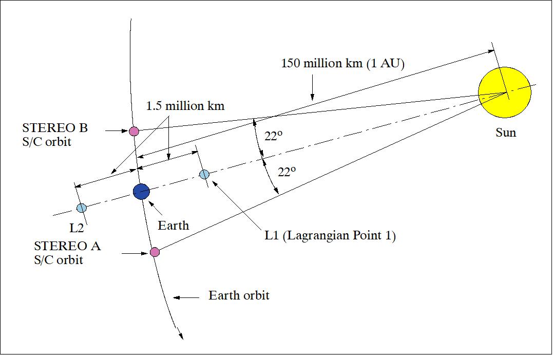
Initial orbit scenario: For the first 3 months after launch, the observatories will fly in highly elliptical orbits called “phasing orbits”. These are orbits from a point close to Earth to one that extends just beyond the moon's orbit. Mission operations personnel at JHU/APL will synchronize the orbits of the two spacecraft to encounter the moon about 2 months after launch. At that point, one spacecraft will use the moon's gravity to redirect it to an orbit lagging “behind” Earth (STEREO B). About 1 month later, the second observatory will encounter the moon again and be redirected to its orbit “ahead” of Earth (STEREO A). After both spacecraft have left the Earth-moon vicinity, they will be in heliocentric orbits at nearly 1 AU. The nominal mission starts when both spacecraft are in heliocentric orbits (about 90 days after launch).
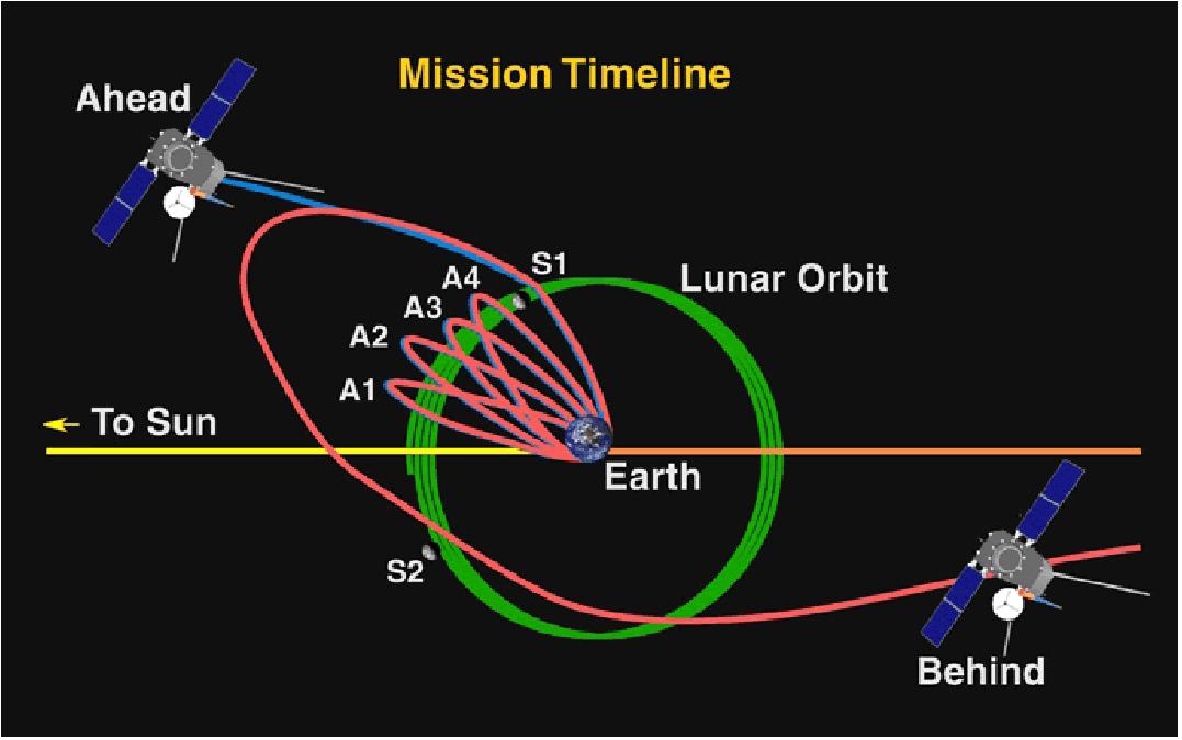
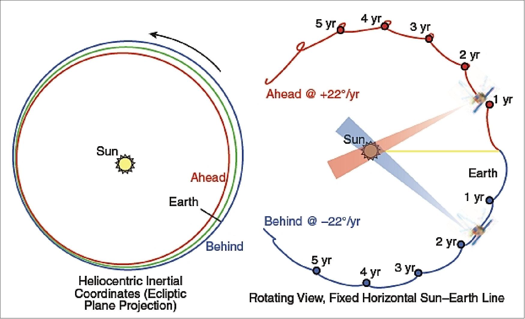
According to Ref. 18), all of the STEREO maneuvers were performed extremely accurately. This performance combined with STEREO’s accurate launch have left the spacecraft with a generous supply of fuel, with an ~60 m/s ΔV capacity that could be used for future spacecraft operations.
The additional maneuvers for Behind ended up targeting its drift rate to -22.000º/year, exactly the desired value. In December 2008, the mission design team suggested modifying the maneuvers to achieve a -22.5º/year drift rate, which would add up to 360º and an Earth return in 2023, 16 years after launch. But with the current drift rates, Ahead’s closest approach to Earth in 2023 will be 8.2 million km on 20 August, whereas Behind’s will be 10.0 million km on 14 July. Using approximately half of the remaining propellant could change the current drift rates to 22.5º/year.
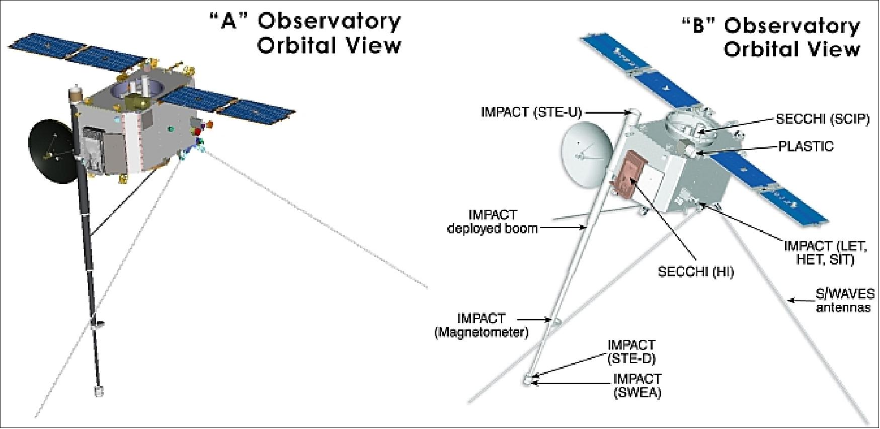
The STEREO mission makes use of simultaneous interplanetary spacecraft operation and stereographic image reconstruction to develop a comprehensive 3-D description of the sun and the heliosphere. Payload operations will be conducted remotely from each of the instruments' facilities:
• SECCHI - Naval Research Laboratory
• IMPACT - University of California, Berkeley
• PLASTIC - University of New Hampshire
• SWAVES - Paris Observatory, Meudon/University of Minnesota
Launch
A launch of the twin STEREO satellites took place on Oct. 26, 2006 (UTC) in a stacked configuration using a Delta-II 7925-10L vehicle from Cape Canaveral Air Force Station, FLA.
Mission Status
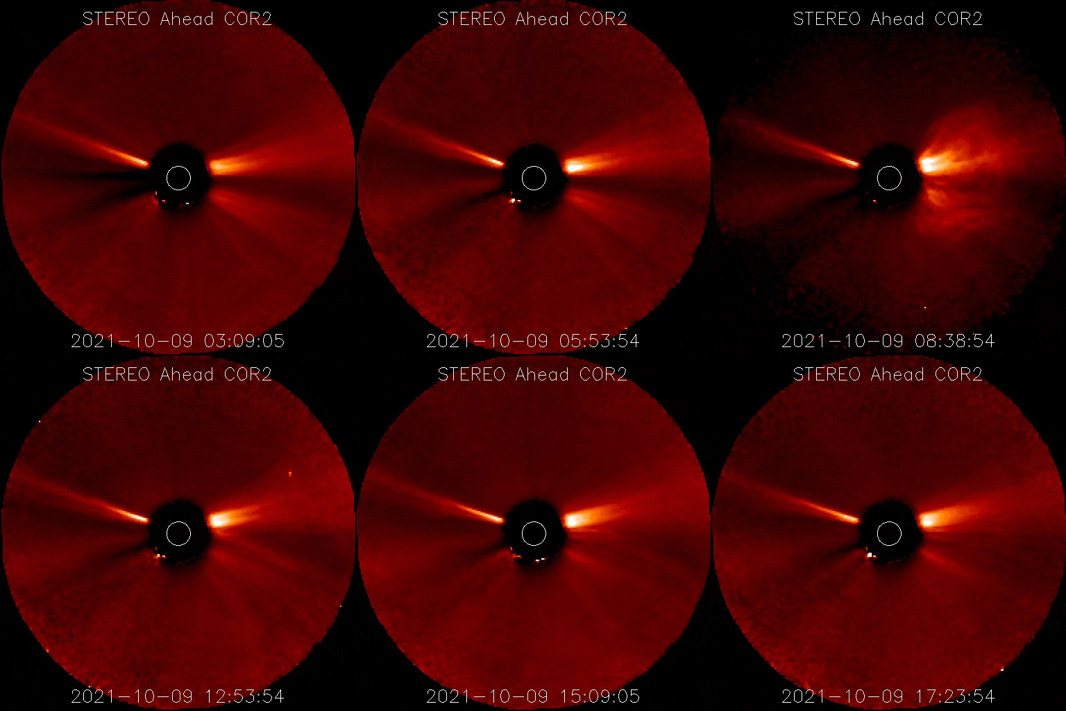
• October 13, 2021: A mass of solar material that erupted from the Sun on Oct. 9, 2021, reached Earth on Oct. 12. The Earth-directed CME (Coronal Mass Ejection) elevated the Kp index, a measure of disturbance to Earth’s magnetic field, to 6 (moderate level). Kp index levels range from 0 (quiet) to 9 (intense). 19)
- The CME was associated with an M1.6 class solar flare from Active Region 2882 on that peaked on Oct. 9 at 6:38 UTC (2:38 a.m. EDT). M-class flares are a tenth the size of the most intense flares, the X-class flares. The number provides more information about its strength. An M2 is twice as intense as an M1, an M3 is three times as intense, etc. The flare also generated a solar energetic particle eruption that was detected by NASA’s Solar Terrestrial Relations Observatory-Ahead, or STEREO-A spacecraft, at 7:51 UTC (3:51 a.m. EDT).
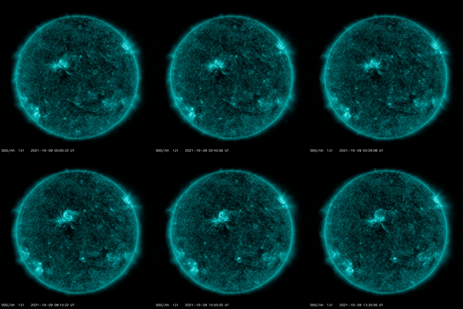
- STEREO-A also detected the CME from its vantage point away from Earth. The CME’s initial speed was estimated by NASA’s Moon to Mars Space Weather Operations Office to be approximately 983 km/s (610 miles per second). This and other information about the event is reported in the Space Weather Database Of Notifications, Knowledge, Information (DONKI) catalog.
- NOAA’s Space Weather Prediction Center is the official source for space weather forecasts, watches, warnings and alerts. Visit https://www.swpc.noaa.gov/ for information about potential impacts from this event.
• April 22, 2021: NASA’s STEREO-A and ESA/NASA’s SOHO spacecraft detected a CME (Coronal Mass Ejection) leaving the Sun on April 17 at 12:36 p.m. EDT. This CME did not impact Earth but did move toward Mars, passing the planet in the late evening and early morning hours of April 21 and 22. 20)
- The CME reached Mars two days after NASA’s Ingenuity Mars Helicopter became the first aircraft in history to make a powered, controlled flight on another planet. NASA tracks such solar eruptions because solar eruptions can trigger particle and radiation events that pose a risk to astronauts and sensitive spacecraft electronics. As astronauts venture beyond Earth’s protective magnetic field to the Moon and Mars, NASA’s Moon to Mars Space Weather Office at NASA Goddard Space Flight Center in Greenbelt, Maryland, in collaboration with the Community Coordinated Modeling Center tracks solar activity to give advanced warning to spacecraft and crewed missions.
- The CME was a relatively slow one, traveling between 1.5 and 1.8 million miles an hour (700 and 800 km/s). It caused no issues for concern and the Ingenuity team did not need to take any steps to protect the helicopter. As we go forward, however, NASA will continue to include space weather updates as a factor when making decisions around our technology – and one day, astronauts – on Mars.

• June 5, 2020: NASA’s Solar Terrestrial Relations Observatory, or STEREO-A spacecraft, captured these images of comet ATLAS as it swooped by the Sun from May 25 – June 1. During the observations and outside STEREO’s field of view, ESA/NASA’s Solar Orbiter spacecraft crossed one of the comet’s two tails. 21)

- In the animated image, ATLAS emerges from the top of the frame and approaches the Sun — off camera to left — against gusts of solar wind. Its dust tail, which reflects sunlight, appears white. Mercury is also visible as a bright dot emerging from the left against the stationary starfield. The vertical streaks in the image are artifacts created by saturation from bright background stars.
- While STEREO recorded this footage, Solar Orbiter crossed one of comet ATLAS’s tails. Launched in February 2020, the spacecraft wasn’t scheduled to enter full science operations until June 15, but engineers adjusted Solar Orbiter’s testing schedule and turned on its four most relevant instruments for the encounter. It’s the first time a comet tail crossing by a spacecraft not designed to chase them was predicted in advance.
- As material sheds from a comet’s nucleus, it leaves behind two tails: a thin ion tail, made of charged particles, and a more diffuse dust tail that reflects visible light. The ion tail always points away from the Sun regardless of the comet’s trajectory; the dust tail more closely follows the comet’s path. Solar Orbiter crossed the ion tail on May 31, some 27 million miles downstream and outside STEREO’s field of view. The team is still awaiting those results. It will fly through the remnants of the dust tail on June 6.
- Comet ATLAS was discovered on Dec. 28, 2019 in images captured by the ATLAS (Asteroid Terrestrial-impact Last Alert System) robotic astronomical survey system in Hawaii. Comets are traditionally named after the instruments or person that discovered them. The comet follows an orbit that takes it past the Sun approximately every 6,000 years, though observations suggest the comet is currently disintegrating and is unlikely to return. It likely originated in the Oort cloud, a spherical cloud of ice and rocks surrounding our solar system. The Oort cloud begins about 185 billion miles away, some 67 times farther than Neptune.
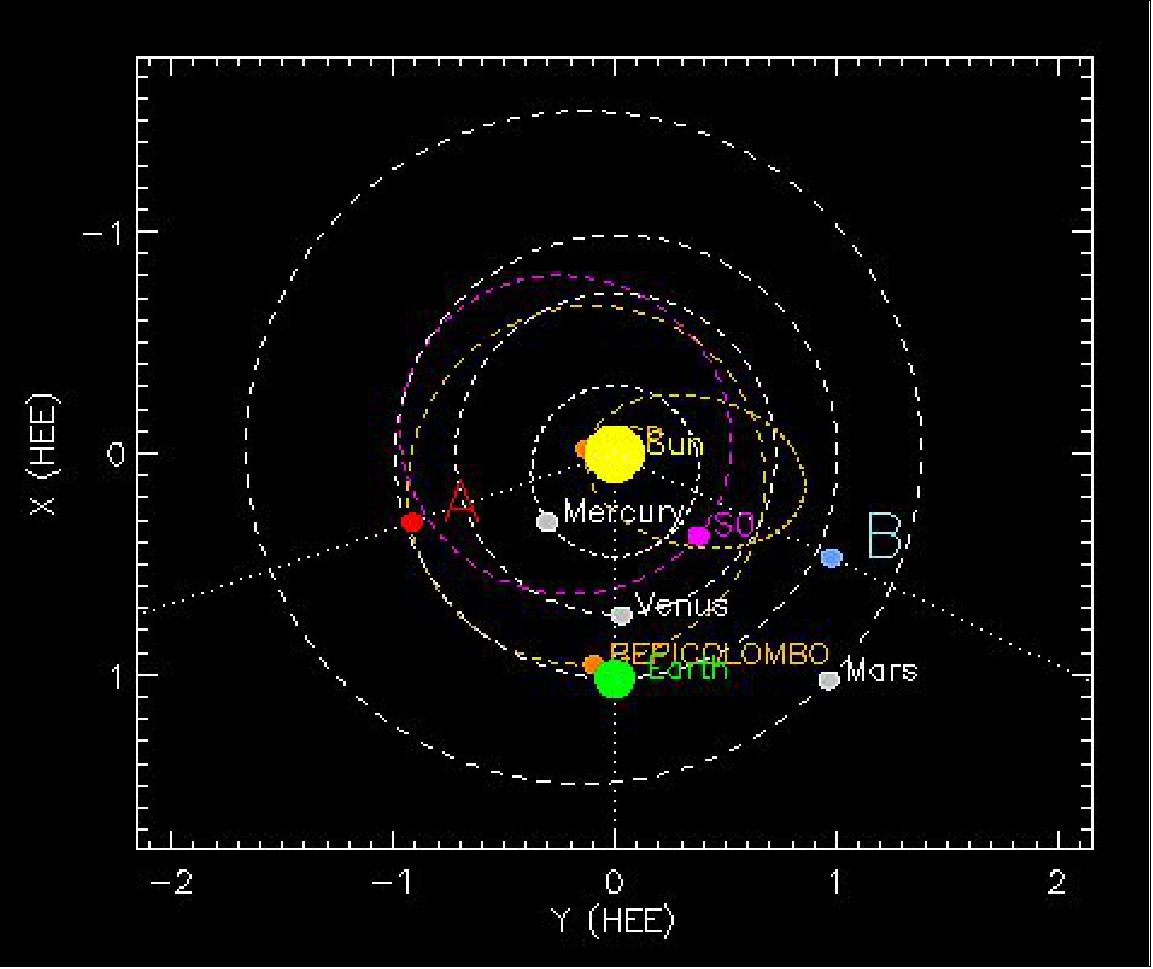
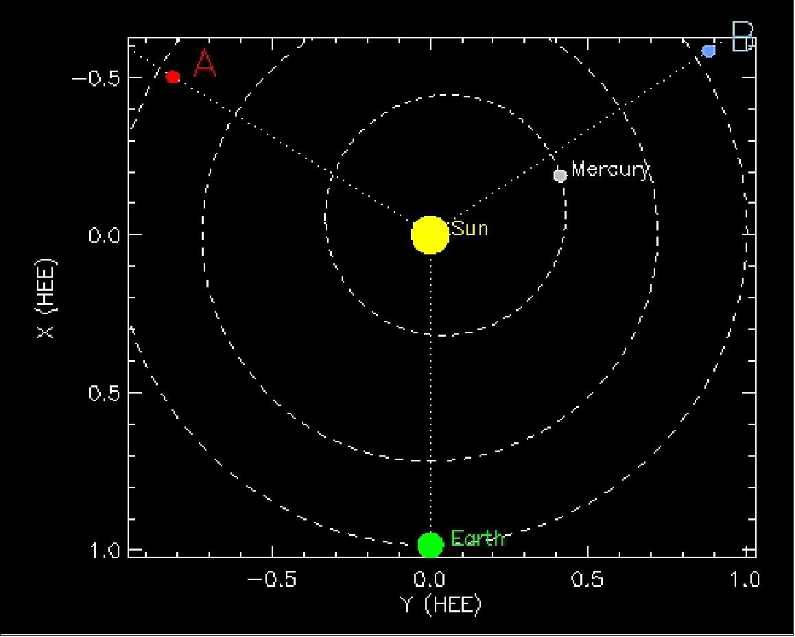
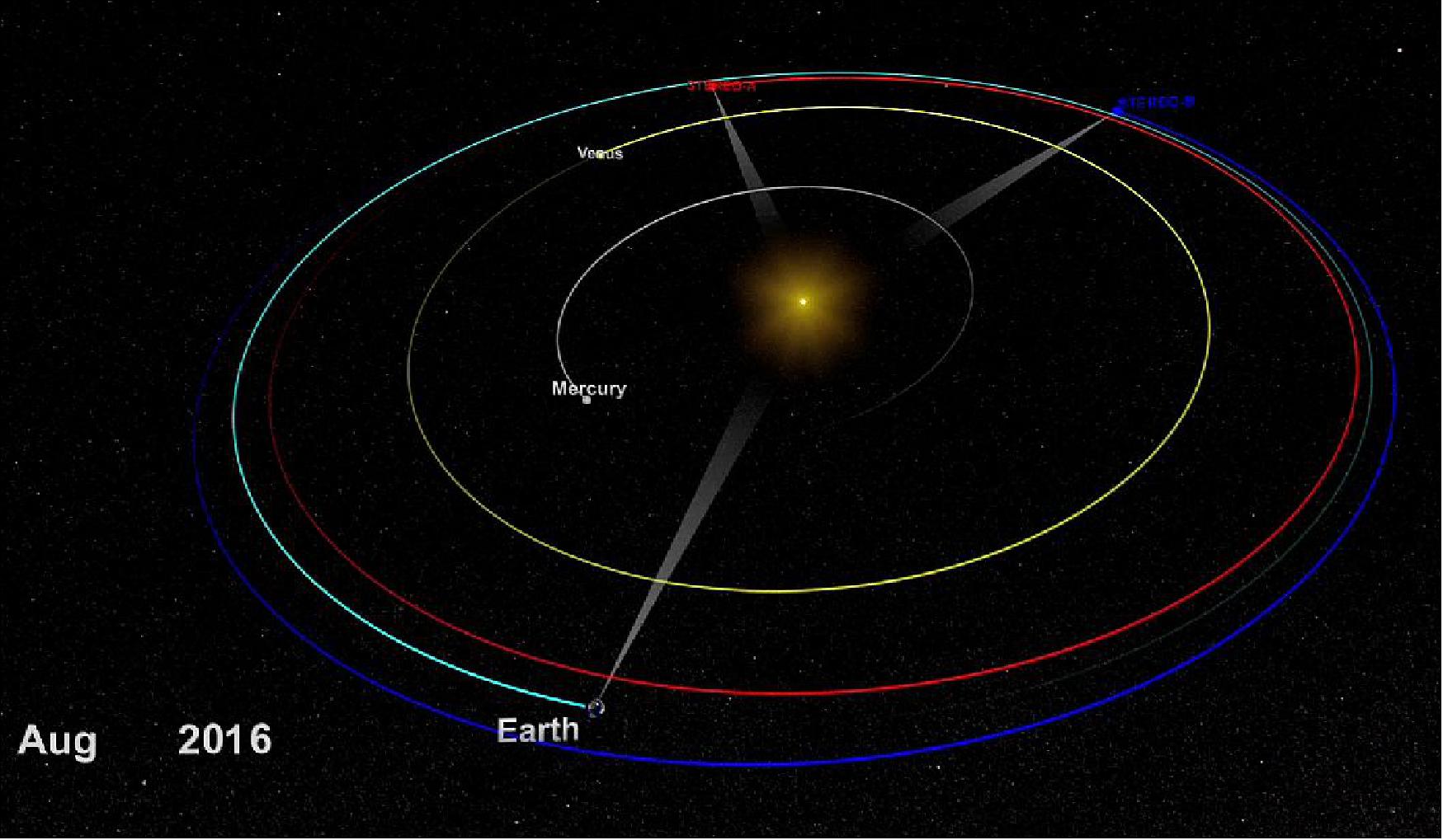
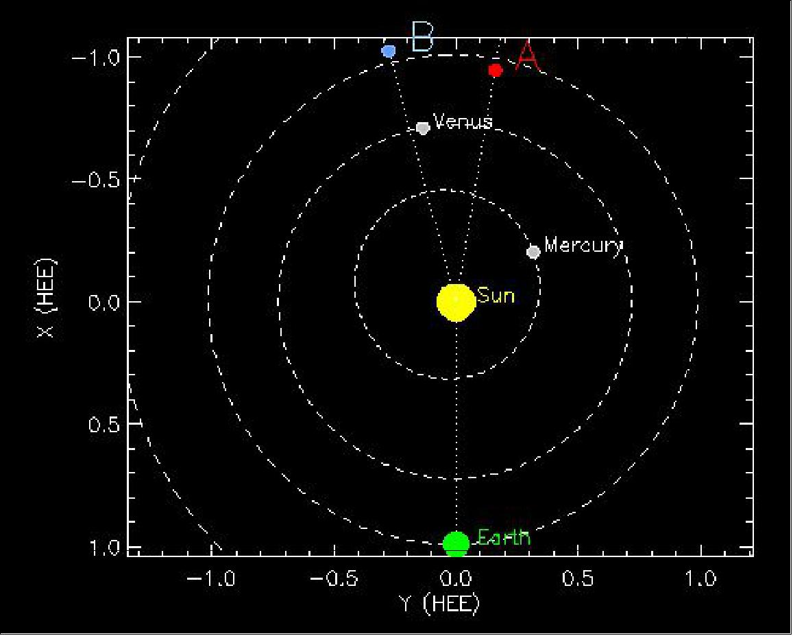
• Positions of STEREO A and B for 7 June 2020 at 11:00 UT (Figure 17). 22)
• The PLASTIC (PLAsma and SupraThermal Ion and Composition) instrument suffered a background anomaly on Dec. 5 2019 that affected the high voltages. Data through February 2019 are test scenarios. Data after February are at lower operational voltages than previously and are undergoing a revised calibration.
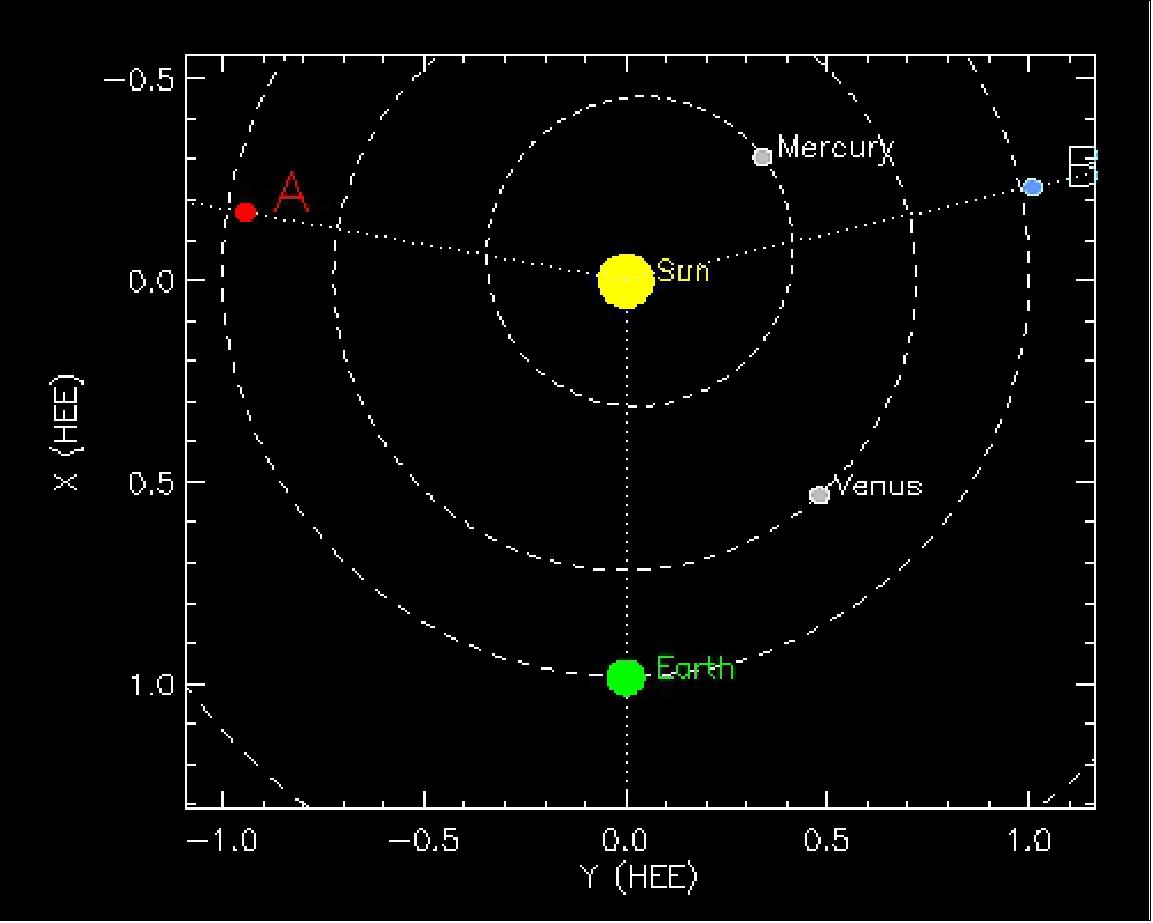
• January 4, 2019: Positions of STEREO-A and -B for 4 January 2019 at 13:00 UT. 23)
• January 5, 2019: Communications with Solar Terrestrial Relations Observatory-B (STEREO-B) were lost on Oct. 1, 2014, due to multiple hardware anomalies affecting control of the spacecraft orientation. Communications with STEREO-B were re-established on Aug. 21, 2016, during a monthly attempt to reach the spacecraft using NASA's Deep Space Network. During the next weeks, the NASA and the Johns Hopkins APL STEREO teams worked tirelessly to discover the spacecraft's current conditions and to recover the spacecraft fully. The attempt to recover the spacecraft was not successful. STEREO-B has now been out of contact since Sept. 23, 2016. Four years after the initial loss of communications anomaly with the Behind observatory, NASA directed that periodic recovery operations cease with the last support on October 17, 2018. 24)
- LOSS HISTORY: Communications with STEREO-B were lost on Oct. 1, 2014, during a test of the spacecraft's command loss timer, a hard reset that is triggered after the spacecraft goes without communications from Earth for 72 hours. This test was in preparation for STEREO to be out of contact with Earth as it passed behind the sun. This event is known as solar conjunction and disrupts the DSN's ability to communicate with the spacecraft; as conjunction occurred beyond STEREO's two-year design mission lifetime, STEREO had no design requirements anticipating periods of weeks without communications. During this two to three week period, STEREO's command loss timer would have expired multiple times.
- RECOVERY ATTEMPTS: After a persistent search and utilizing a special command sequence designed to interrupt a cycle of collapsing battery voltage, communications with STEREO-B were re-established on Aug. 21, 2016. During the next weeks, the STEREO team worked to learn more about the state of the spacecraft and to recover it. However, data was very limited; the large distance to the spacecraft (~2 AU) and the uncontrolled orientation meant that while the DSN could detect that STEREO-B was transmitting, very few packets of telemetry — containing the on-board measurements of temperatures, voltages, etc. - were, in fact, received.
With the limited data available, the team formulated a plan to attempt a recovery and stabilize the spacecraft pointing. The attempt was not successful. The limited data available during the recovery attempt revealed that STEREO-B came close to achieving a stable orientation, but one set of thrusters on-board may have performed abnormally, possibly due to frozen propellant and ultimately spun the spacecraft back up into an uncontrolled state. STEREO-B has now been out of contact since September 23. The information during those few weeks has provided guidance for plans forward, however, and the team will continue to try to reestablish communication.
- INFORMATION LEARNED: The 2016 contact with STEREO-B revealed new information about the spacecraft's rate of spin and precise location in space - which is particularly important since, when contact was lost, it wasn't clear if STEREO-B had fired its thrusters in such a way as to affect its expected orbit. Data from STEREO-B also shows that the spacecraft battery is operating with very low charge, a challenge made more difficult to overcome by the fact that STEREO-B's solar panels are no longer pointed directly at the sun, meaning that the battery charges only a fraction of the time. Mission operators also have new information about how STEREO-B responds to extreme conditions including both very high and low temperatures. STEREO-B has proved to be a resilient spacecraft capable of surviving under an array of circumstances that is was not designed to accommodate. Consequently, the hope of recovery persists.
- GOING FORWARD: As STEREO-B's orbit brings it closer to Earth, the spacecraft's antenna orientation and closing communications gap may improve the chances of further communication.
- STEREO BACKGROUND:
a) The Solar Terrestrial Relations Observatory is part of the Heliophysics Systems Observatory, a collection of missions that observes the sun and our space environment, providing research that contributes to the safety of spacecraft both in near-Earth space and as they travel further from home.
b) STEREO consists of two nearly identical spacecraft put into slightly different orbits around the sun - one moving faster than Earth, one moving more slowly - so they each have a different vantage point of the star.
c) Launched in October 2006, the STEREO mission design lifetime was two years. Having delivered far beyond expectations, the mission is now poised to enter its second decade of operations.
d) The STEREO mission was designed to provide the first-ever stereoscopic measurements of the sun, providing 3-dimensional views of the structure and evolution of eruptions on the sun - eruptions such as coronal mass ejections that can disrupt the space environment near Earth and interfere with radio communications and satellite electronics.
e) STEREO-A continues to operate normally. STEREO's current mission extension was based on using just one spacecraft, so, regardless of what happens with STEREO-B, the STEREO mission will provide robust solar research in the coming years.
Planned research is to characterize space weather throughout the inner heliosphere, support 360 degree coverage of the sun (along with SDO and SOHO) and improve our understanding of phenomena from the sun's atmosphere, all the way to the edges of the heliosphere.
f) STEREO is the third mission in NASA's Solar Terrestrial Probes program, which is managed by NASA Goddard for NASA's Heliophysics Division of the Science Mission Directorate, in Washington. The Johns Hopkins University Applied Physics Laboratory, in Laurel, Maryland, designed, built and operates the twin observatories.
• November 2, 2018: Engineers and scientists gathered around a screen in an operations room at the Naval Research Laboratory in Washington, D.C., eager to lay their eyes on the first data from NASA’s STEREO spacecraft. It was January 2007, and the twin STEREO satellites — short for Solar and Terrestrial Relations Observatory — which had launched just months before, were opening their instruments’ eyes for the first time. First up: STEREO-B. The screen blinked, but instead of the vast starfield they expected, a pearly white, feathery smear — like an angel’s wing — filled the frame. For a few panicky minutes, NRL astrophysicist Karl Battams worried something was wrong with the telescope. Then, he realized this bright object wasn’t a defect, but an apparition, and these were the first satellite images of Comet McNaught. Later that day, STEREO-A would return similar observations. 25)
- Comet C/2006 P1 — also known as Comet McNaught, named for astronomer Robert McNaught, who discovered it in August 2006 — was one of the brightest comets visible from Earth in the past 50 years. Throughout January 2007, the comet fanned across the Southern Hemisphere’s sky, so bright it was visible to the naked eye even during the day. McNaught belongs to a rarefied group of comets, dubbed the Great Comets and known for their exceptional brightness. Setting McNaught apart further still from its peers, however, was its highly structured tail, composed of many distinct dust bands called striae, or striations, that stretched more than 100 million miles behind the comet, longer than the distance between Earth and the Sun. One month later, in February 2007, an ESA (European Space Agency) and NASA spacecraft called Ulysses would encounter the comet’s long tail.
- “McNaught was a huge deal when it came because it was so ridiculously bright and beautiful in the sky,” Battams said. “It had these striae — dusty fingers that extended across a huge expanse of the sky. Structurally, it’s one of the most beautiful comets we’ve seen for decades.”
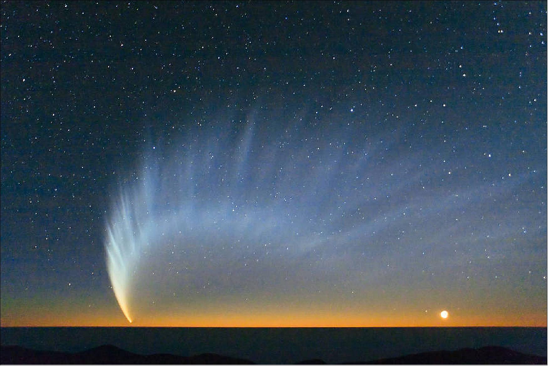
- How exactly the tail broke up in this manner, scientists didn’t know. It called to mind reports of another storied comet from long ago: the Great Comet of 1744, which was said to have dramatically fanned out in six tails over the horizon, a phenomenon astronomers then couldn’t explain. By untangling the mystery of McNaught’s tail, scientists hoped to learn something new about the nature of comets — and solve two cosmic mysteries in one.
- A key difference between studying comets in 1744 and 2007 is, of course, our ability to do so from space. In addition to STEREO’s serendipitous sighting, another mission, ESA/NASA’s SOHO (Solar and Heliospheric Observatory) — made regular observations as McNaught flew by the Sun. Researchers hoped these images might contain their answers.
- Now, years later, Oliver Price, a planetary science Ph.D. student at University College London’s Mullard Space Science Laboratory in the United Kingdom, has developed a new image-processing technique to mine through the wealth of data. Price’s findings — summarized in a recently published Icarus paper — offer the first observations of striations forming, and an unexpected revelation about the Sun’s effect on comet dust. 26)
- Comets are cosmic crumbs of frozen gas, rock and dust left over from the formation of our solar system 4.6 billion years ago — and so they may contain important clues about our solar system’s early history. Those clues are unlocked, as if from a time capsule, every time a comet’s elliptical orbit brings it close to the Sun. Intense heat vaporizes the frozen gases and releases the dust within, which streams behind the comet, forming two distinct tails: an ion tail carried by the solar wind — the constant flow of charged particles from the Sun — and a dust tail.
- Understanding how dust behaves in the tail — how it fragments and clumps together — can teach scientists a great deal about similar processes that formed dust into asteroids, moons and even planets all those billions of years ago. Appearing as one of the biggest and most structurally complex comets in recent history, McNaught was a particularly good subject for this type of study. Its brightness and high dust production made it much easier to resolve the evolution of fine structures in its dust tail.
- Price began his study focusing on something the scientists couldn’t explain. “My supervisor and I noticed weird goings-on in the images of these striations, a disruption in the otherwise clean lines,” he said. “I set out to investigate what might have happened to create this weird effect.”
- The rift seemed to be located at the heliospheric current sheet, a boundary where the magnetic orientation, or polarity, of the electrified solar wind changes directions. This puzzled scientists because while they have long known a comet’s ion tail is affected by the solar wind, they had never seen the solar wind impact dust tails before.
- Dust in McNaught’s tail — roughly the size of cigarette smoke — is too heavy, the scientists thought, for the solar wind to push around. On the other hand, an ion tail’s miniscule, electrically charged ions and electrons easily sail along the solar wind. But it was difficult to tell exactly what was going on with McNaught’s dust, and where, because at roughly 100 km/s, the comet was rapidly traveling in and out of STEREO and SOHO’s view.
- “We got really good data sets with this comet, but they were from different cameras on different spacecraft, which are all in different places,” Price said. “I was looking for a way to bring it all together to get a complete picture of what’s happening in the tail.”
- His solution was a novel image-processing technique that compiles all the data from different spacecraft using a simulation of the tail, where the location of each tiny speck of dust is mapped by solar conditions and physical characteristics like its size and age, or how long it’d been since it’d flown off the head, or coma, of the comet. The end result is what Price dubbed a temporal map, which layers information from all the images taken at any given moment, allowing him to follow the dust’s movements.
- The temporal maps meant Price could watch the striations form over time. His videos, which cover the span of two weeks, are the first to track the formation and evolution of these structures, showing how dust fragments topple off the comet head and collapse into long striations.
- But the researchers were most excited to find that Price’s maps made it easier to explain the strange effect that drew their attention to the data in the first place. Indeed, the current sheet was the culprit behind the disruptions in the dust tail, breaking up each striation’s smooth, distinct lines. For the two days it took the full length of the comet to traverse the current sheet, whenever dust encountered the changing magnetic conditions there, it was jolted out of position, as if crossing some cosmic speed bump.
- “It’s like the striation’s feathers are ruffled when it crosses the current sheet,” University College London planetary scientist Geraint Jones said. “If you picture a wing with lots of feathers, as the wing crosses the sheet, lighter ends of the feathers get bent out of shape. For us, this is strong evidence that the dust is electrically charged, and that the solar wind is affecting the motion of that dust.”
- Scientists have long known the solar wind affects charged dust; missions like Galileo, Cassini and Ulysses watched it move electrically charged dust through the space near Jupiter and Saturn. But it was a surprise for them to see the solar wind affect larger dust grains like those in McNaught’s tail — about 100 times bigger than the dust seen ejected from around Jupiter and Saturn — because they’re that much heavier for the solar wind to push around.
- With this study, scientists gain new insights into long-held mysteries. The work sheds light on the nature of striated comet tails from the past and provides a crucial lens for studying other comets in the future. But it also opens a new line of questioning: What role did the Sun have in our solar system’s formation and early history?
- “Now that we see the solar wind changed the position of dust grains in McNaught’s tail, we can ask: Could it have been the case that early on in the solar system’s history, the solar wind played a role in organizing ancient dust as well?” Jones said.
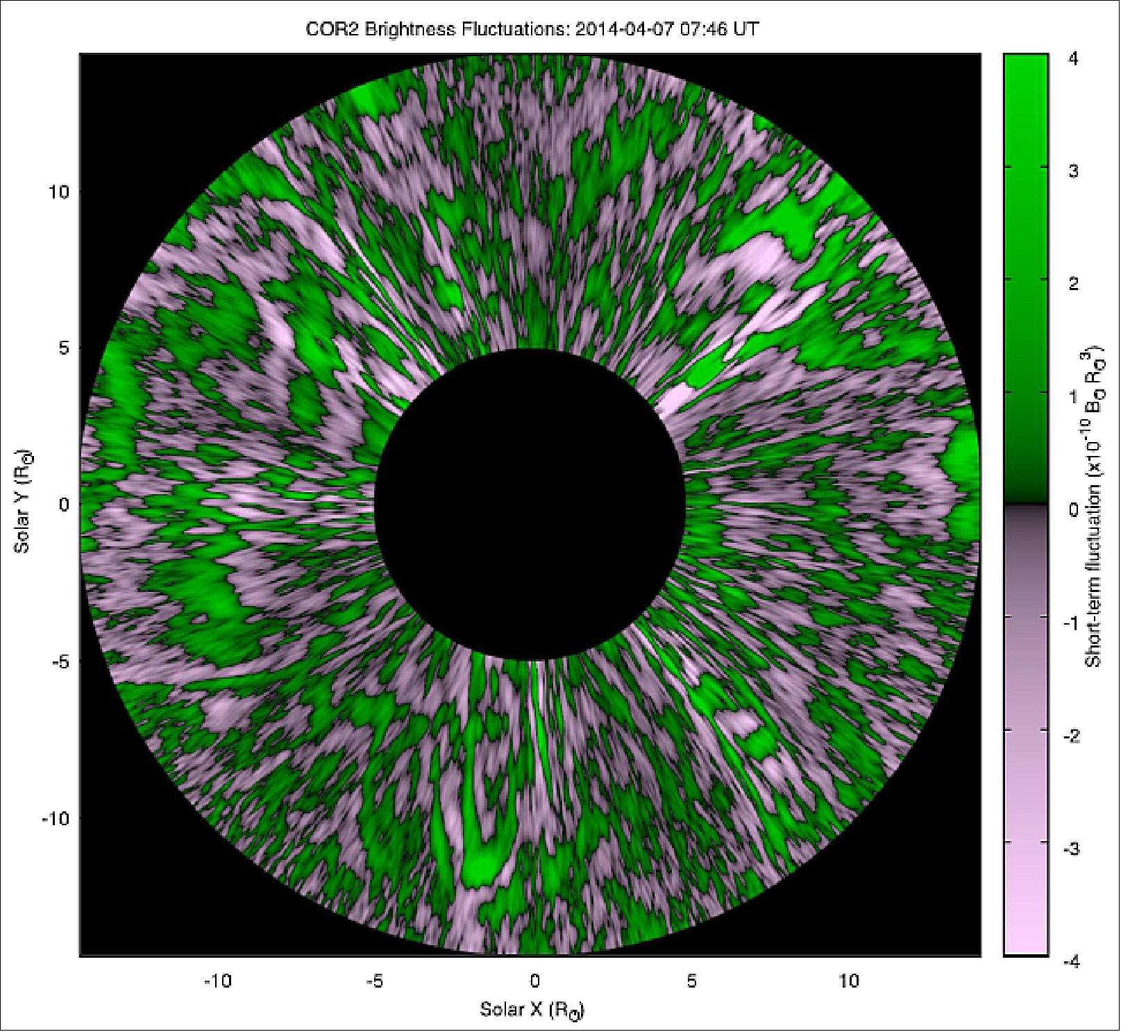
• July 18, 2018: A Southwest Research Institute-led team discovered never-before-detected, fine-grained structures in the Sun’s outer atmosphere, or corona. The team imaged this critical region in detail using sophisticated software techniques and longer exposures from the COR-2 (Coronagraph-2 camera), part of the SECCHI suite, on board NASA’s STEREO-A (Solar and Terrestrial Relations Observatory-A). 27)
- The Sun’s outer corona is the source of the solar wind, the stream of charged particles that flow outward from the Sun in all directions. Measured near Earth, the magnetic fields embedded within the solar wind are intertwined and complex.
- “Previous images showed the outer corona as a smooth structure, but in deep space, the solar wind is turbulent and gusty,” said SwRI’s Dr. Craig DeForest, a solar physicist and lead author of “The Highly Structured Outer Corona,” an article published by Astrophysical Journal July 18, 2018. “Using new techniques to improve image fidelity, we realized that the corona is not smooth, but structured and dynamic. Every structure that we thought we understood turns out to be made of smaller ones, and to be more dynamic than we thought.” 28)
- To understand the corona, DeForest and his colleagues started with extended exposures of STEREO-A’s coronagraph images — pictures of the Sun’s atmosphere produced by a special telescope that blocks out light from the bright solar disk. The coronagraph is sensitive enough to image the corona in great detail, but in practice its measurements are polluted by noise both from the space environment and the instrument itself. The team’s key innovation was identifying and separating out that noise, boosting the signal-to-noise ratio and revealing the outer corona in unprecedented detail.
- “We couldn’t tinker with the instrument itself, so we took a software approach, squeezing out the highest quality data possible by improving the data’s signal-to-noise ratio,” DeForest said. “We developed new filtering algorithms, designed and tested to delineate the true corona from the noisy measurements.”
- The algorithms filtered out light and adjusted brightness. But the most challenging obstacle is inherent: blur due to the motion of the solar wind. “This technique adjusted images not just in space, not just in time, but in a moving coordinate system,” DeForest said. “That allowed us to correct motion blur not just by the speed of the wind, but by how rapidly features changed in the wind.”
- With the resulting unprecedented view of the corona, the team made several groundbreaking discoveries. For example, coronal streamers — magnetic loops that can erupt into coronal mass ejections that send blobs of solar material into space — are far more structured than previously thought.
- “What we found is that there is no such thing as a single streamer,” DeForest said. “The streamers themselves are composed of myriad fine strands that, together, average to produce a brighter feature.”
- Then there’s the theoretical Alfvén surface — a proposed surface, or sheet-like layer where the gradually accelerating solar wind reaches a critical speed. But that’s not what DeForest’s team observed.
- “What we found is that there isn’t a clean Alfvén surface,” DeForest said. “There’s a wide ‘no-man’s land’ or `Alfvén zone’ where the solar wind gradually disconnects from the Sun, rather than a single clear boundary.”
- And the close look at the coronal structure also raised new questions. Techniques used to estimate the speed of the solar wind revealed that the wind suddenly changes its character at a distance of around 10 solar radii, well within the conventional boundary of the corona itself.
- “Some interesting physics is happening around there,” DeForest said. “We don’t know what it is yet, but we do know that it is going to be interesting.”
- These first observations will provide key insight for NASA’s upcoming Parker Solar Probe, the first-ever mission to gather measurements from within the outer solar corona.
- The NASA Living with a Star program, managed by the Goddard Space Flight Center, funds the STEREO mission and supported this research with a targeted research and technology grant. The COR-2 instrument was built and is operated by the Naval Research Laboratory as part of the STEREO mission.
• January 15, 2018: Positions of STEREO-A and -B for 15 January 2018 at 16:00 UT. 29)
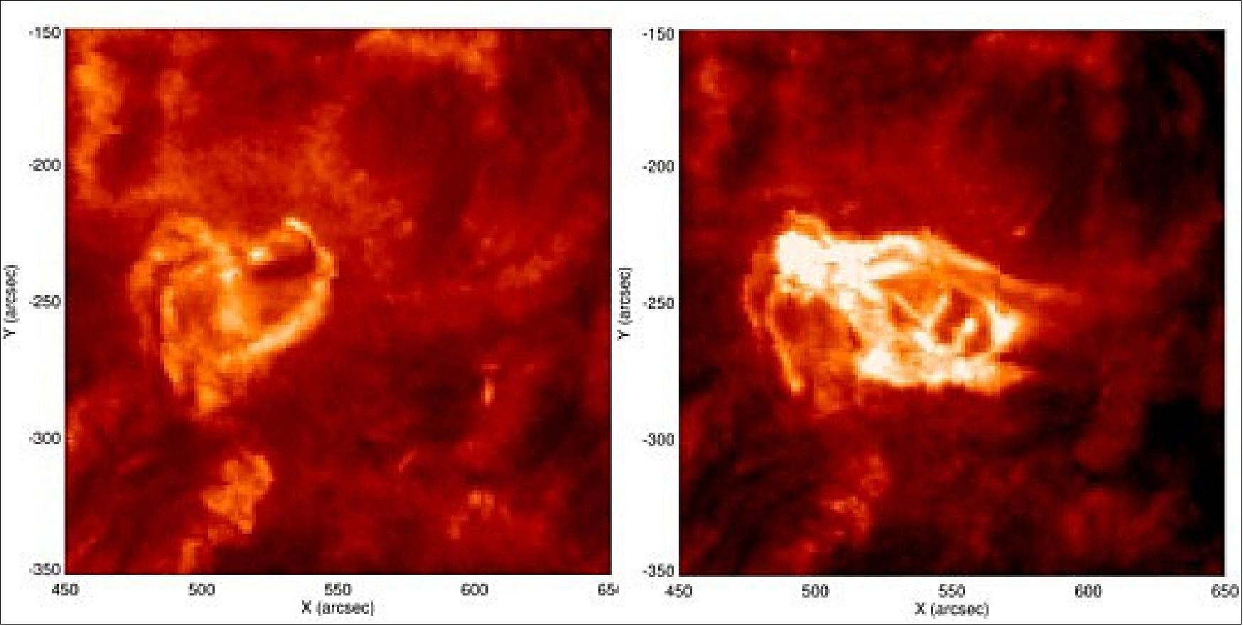
• January 10, 2018: Why does the Sun sometimes accelerate preferentially helium-3 and iron into space? Researchers have for the first time observed helical solar flares as a source. 30)
- In April and July 2014, the Sun emitted three jets of energetic particles into space, that were quite exceptional: the particle flows contained such high amounts of iron and helium-3, a rare variety of helium, as have been observed only few times before. Since these extraordinary events occurred on the backside of our star, they were not discovered immediately. A group of researchers headed by the MPS (Max Planck Institute for Solar System Research) and the Institute for Astrophysics of the University of Göttingen (Germany) present a comprehensive analysis now in the Astrophysical Journal. It is based on data from the twin space probes STEREO-A and STEREO-B, which – at that time still both operating – were in a favorable observation position behind the Sun at the crucial time. For the first time, the study shows a correlation between helium-3 and iron-rich particle flows and helical eruptions of ultraviolet radiation in the Sun's atmosphere. These could provide the necessary energy to accelerate the particles into space. 31)
- Sudden particle emissions, in which our star repeatedly hurls large amounts of charged and uncharged particles into space, are still a mystery. Some of these particle flows are accompanied by violent solar flares, a sudden and local increase of the Sun’s brightness, and contain up to 10,000 times more helium-3 and up to 10 times more iron than the Sun's atmosphere. Why is this extremely rare helium isotope accelerated into space so efficiently? And why iron? How does the Sun supply these particles with the necessary energy to catapult them into space?
- "The events, that took place on the backside of the Sun in April and July 2014, were particularly intense and allowed for unusually extensive insights”, says Radoslav Bučík from the MPS. Only seldomly does the Sun emit particle flows so heavily enriched in helium-3 and heavier elements into space – and often they do not originate from the “right” place. Most space probes studying the Sun do so from an observational position close to Earth. They therefore see only the side of the Sun facing the Earth. Only the spacecraft STEREO-A and -B, which have been orbiting our star from opposite sides since 2006, began to observe the Sun’s far side in 2011.
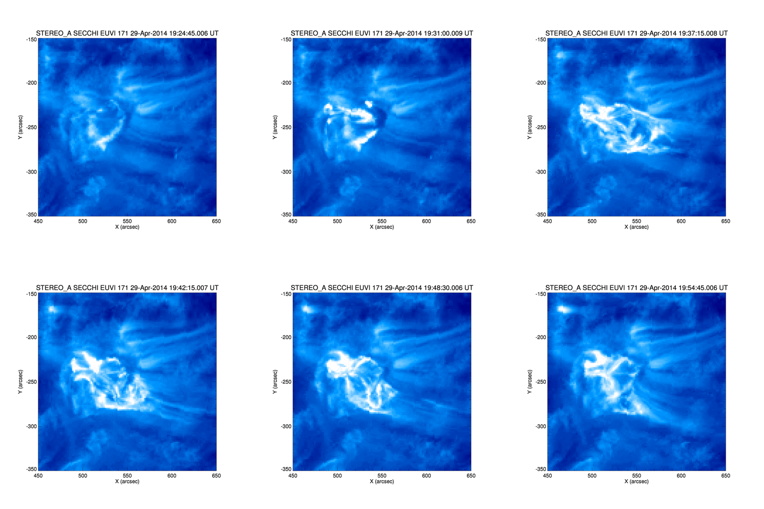
- Shortly before the control center lost contact to STEREO-B in October 2014, both probes witnessed the "hidden" particle eruptions on 30 April 2014 and 17 and 20 July 2014. The eruptions lasted up to three days each. "The amount of helium-3 and iron in them was increased as much as in just a handful of other known events," Bučík describes the measurements.
- While the ion telescope SIT (Suprathermal Ion Telescope) on board the STEREO probes recorded the composition of the particle streams, the EUVI instruments (Extreme Ultraviolet Imager), parts of STEREO’s instrument package SECCHI (Sun Earth Connection Coronal and Heliospheric Investigation), looked at their regions of origin in the atmosphere of the Sun. There, the scientists found the typical increase of extreme ultraviolet radiation, which is usually accompanied by particle events of this kind, but this time in an unfamiliar form: helical movements were clearly recognizable.
- "This is the first time that we have seen a twisted radiation outburst as the source of helium-3 and iron-rich particle flows," says Bučík. The radiation is caused by hot plasma moving along the constantly swirling and changing magnetic field lines in the Sun's atmosphere. When these field lines regroup, there may be a sudden release of energy. "The helical magnetic fields seem to efficiently provide helium-3 and iron in the solar atmosphere with energy - much like a spring coil that is suddenly released," said Bučík.
- "Only by further exploring this mechanism can we better understand other solar outbursts," says Nariaki Nitta of the Lockheed Martin Advanced Technology Center in Palo Alto, USA. The researchers’ focus is particularly on a further variety of particle events, so-called CMEs (Coronal Mass Ejections). The energy of these particles is very high. They can lead to solar storms on Earth, which endanger, for example, satellites. In rare cases, these ejections are also very rich in iron - and then particularly dangerous because of the particles’ high mass. The researchers now want to investigate whether these iron-rich particles outbursts, too, are accelerated by helical radiation bursts.
- This research project was funded by the Deutsche Forschungsgemeinschaft (DFG) and the Max Planck Society (MPG).
• December 19, 2017: Despite its smooth appearance, the sun’s wispy outer atmosphere is surprisingly full of knots, whorls and blobs. Newly analyzed observations from NASA’s STEREO spacecraft show that the sun’s outer corona is just as complicated as the highly structured inner corona, solar physicists reported December 12 at the fall meeting of the American Geophysical Union. That previously unseen structure could help solve some of the sun’s biggest puzzles, including how the solar wind is born and why the corona is so much hotter than the solar surface. 32)
- The corona is made up of charged plasma, which roils in famous loops and fans that follow magnetic field lines emerging from the surface of the sun (SN Online: 8/17/17). At a certain distance from the sun, though, that plasma escapes the corona and streams through the solar system as the solar wind, a constant flow of charged particles that pummels the planets, including Earth.
- But solar physicists don’t know where the plasma gets enough energy to accelerate away from the massive, magnetic sun. And they don’t understand why the corona, which sizzles at several million degrees Celsius, has such higher temperatures than the solar surface, which chills at a mere 5,500° C.
- Both problems might be cleared up by better understanding an energetic process called reconnection, which happens when magnetic field lines merge when they get too close to each other. Reconnection releases energy and helps move plasma around, so the process could be important to heating the corona and driving solar wind.
- But in the best observations until now, the outer corona appeared smooth and uniform. To explain that smoothness, field lines would have to keep their distance from each other without a lot of reconnection. What’s more, physicists couldn’t tell where the boundary between the corona and the solar wind began, which might help to find that missing energy source.
- “That’s changed,” solar physicist Craig DeForest of the SwRI(Southwest Research Institute) in Boulder, CO, said at the AGU meeting. “Using STEREO, we’ve recently been able to drill in deeply enough to see the transition at the outer edge of the corona, where the dynamics change from what we might call coronal plasma to what we might call the young solar wind plasma.”
- DeForest and colleagues collected data for three days with STEREO in 2014 to gain more detail about small-scale changes in the outer corona than previously obtained. The researchers also processed the resulting images in a new way to bring those changes into focus.
- Surprisingly, the team found that the outer corona is full of moving blobs and fine streams of plasma that vary in density by a factor of 10, suggesting that the magnetic field lines there are moving and merging more than scientists thought. “It turns out the apparent smoothness is a reflection of our instruments, not the corona itself,” DeForest says. “There’s almost certainly reconnection in the outer corona.”
- The researchers also found that the corona probably fades into the solar wind between 14 million and 56 million kilometers away from the sun — about 10 to 40 times the sun’s diameter. That’s still a big range, but NASA’s PSP (Parker Solar Probe) spacecraft, scheduled to launch in 2018, will fly right through that boundary. The probe will swoop within 6.4 million kilometers of the sun and take the first direct measurements of the corona — and perhaps figure out more precisely where the corona becomes the solar wind.
- For now, the STEREO observations “are just tantalizing hints at an entire new set of phenomena,” DeForest says. Understanding the details of those processes “is going to require both careful analysis from Parker Solar Probe and also new, better imaging instruments.”
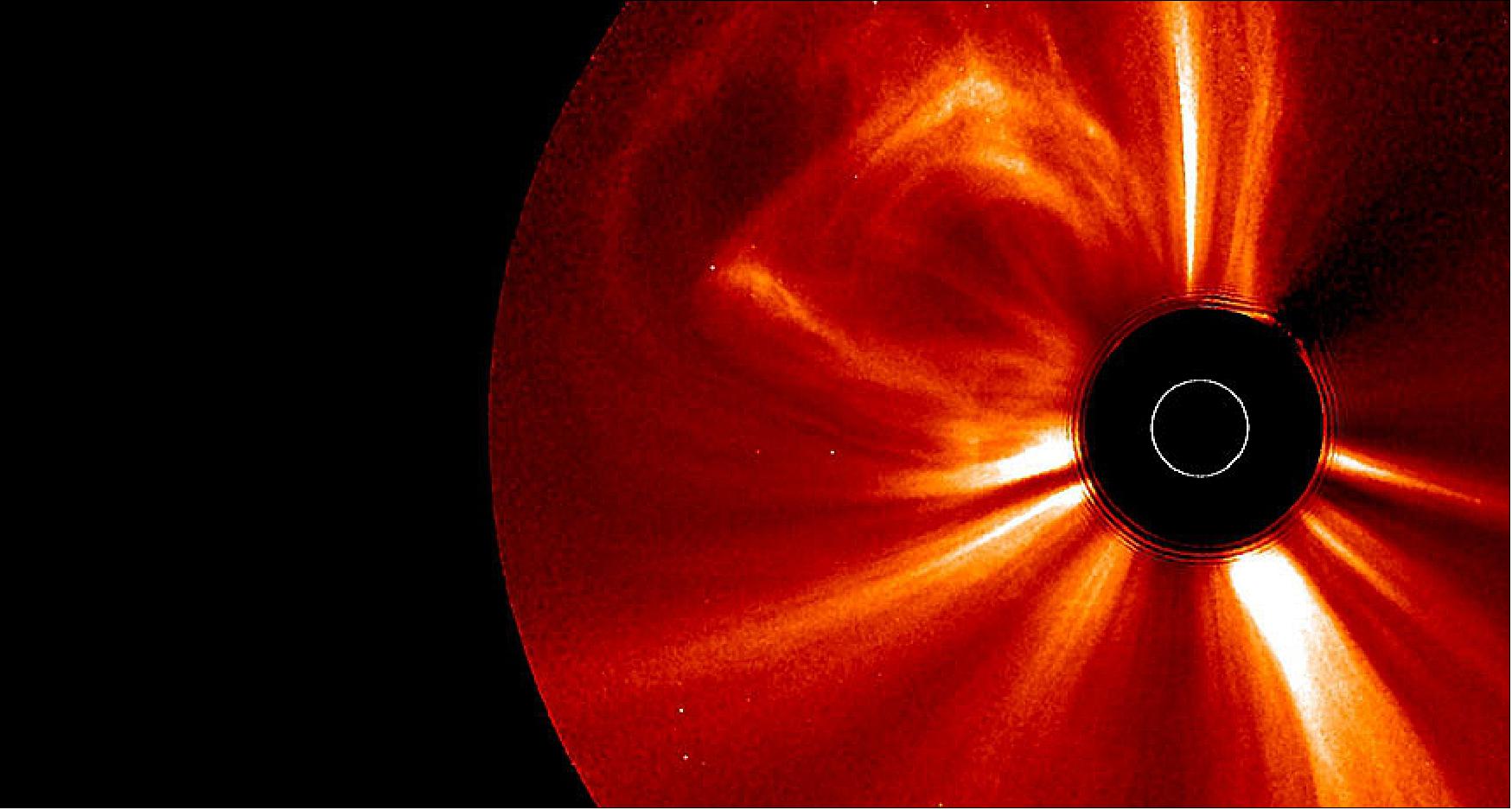
• March 27, 2017: The same kind of large-scale planetary waves that meander through the atmosphere high above Earth's surface may also exist on the Sun, according to a new study led by a scientist at CAR (National Center for Atmospheric Research) in Boulder, CO. 33)
- Just as the large-scale waves that form on Earth, known as Rossby waves, influence local weather patterns, the waves discovered on the Sun may be intimately tied to solar activity, including the formation of sunspots, active regions, and the eruption of solar flares.
- "The discovery of magnetized Rossby waves on the Sun offers the tantalizing possibility that we can predict space weather much further in advance," said NCAR scientist Scott McIntosh, lead author of the paper. The research was funded by the National Science Foundation (NSF), which is NCAR's sponsor, and by NASA. 34)
- An unprecedented view of the Sun: On Earth, Rossby waves are associated with the path of the jet stream and the formation of low- and high-pressure systems, which in turn influence local weather events.
- The waves form in rotating fluids — in the atmosphere and in the oceans. Because the Sun is also rotating, and because it's made largely of plasma that acts, in some ways, like a vast magnetized ocean, the existence of Rossby-like waves should not come as a surprise, said McIntosh, who directs NCAR's High Altitude Observatory.
- And yet scientists have lacked the tools to distinguish this wave pattern until recently. Unlike Earth, which is scrutinized at numerous angles by satellites in space, scientists historically have been able to study the Sun from only one viewpoint: as seen from the direction of Earth.
- But for a brief period, from 2011 to 2014, scientists had the unprecedented opportunity to see the Sun's entire atmosphere at once. During that time, observations from NASA's SDO (Solar Dynamics Observatory), which sits between the Sun and the Earth, were supplemented by measurements from NASA's STEREO (Solar TErrestrial RElations Observatory) mission, which included two spacecraft orbiting the Sun. Collectively, the three observatories provided a 360º view of the Sun until contact was lost with one of the STEREO spacecraft in 2014. McIntosh and his co-authors mined the data collected during the window of full solar coverage to see if the large-scale wave patterns might emerge.
- "By combining the data from all three satellites we can see the entire sun and that's important for studies like this because you want the measurements to all be at the same time," said Dean Pesnell, SDO project scientist at NASA’s Goddard Space Flight Center in Greenbelt, Maryland. "They’re pushing the boundary of how we use solar data to understand the interior of the sun and where the magnetic field of the sun comes from."
- Finding waves in the data: The team used images taken by instruments on SDO and STEREO to identify and track coronal BPs (Bright Points). These small bright features dot the entire face of the Sun and have been used to track motions deeper in the solar atmosphere. - The scientists plotted the combined data on Hovmöller diagrams, a diagnostic tool developed by meteorologists to highlight the role of waves in Earth's atmosphere. What emerged from the analysis were bands of magnetized activity that propagate slowly across the Sun — just like the Rossby waves found on Earth.
- The discovery could link a range of solar phenomena that are also related to the Sun's magnetic field, including the formation of sunspots, their lifetimes, and the origin of the Sun’s 11-year solar cycle. "It's possible that it's all tied together, but we needed to have a global perspective to see that," McIntosh said. "We believe that people have been observing the impacts of these Rossby-like waves for decades, but haven't been able to put the whole picture together."
- With a new understanding of what the big picture might really look like, scientists could take a step closer to predicting the Sun's behavior. "The discovery of Rossby-like waves on the Sun could be important for the prediction of solar storms, the main drivers of space weather effects on Earth," said Ilia Roussev, program director in NSF's Division of Atmospheric and Geospace Sciences. "Bad weather in space can hinder or damage satellite operations, and communication and navigation systems, as well as cause power-grid outages leading to tremendous socioeconomic losses. Estimates put the cost of space weather hazards at $10 billion per year.”
- But to advance our predictive capabilities, scientists must first gain a better understanding of the waves and the patterns that persist on them, which would require once again having a 360º view of the Sun.
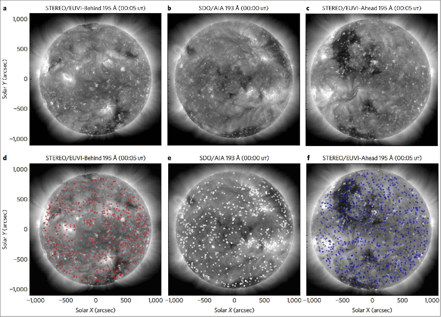
Figure 26: Coronal BP (Bright Point) detection at three distinct vantage points in space. BP detections by the STEREO and SDO spacecraft taken around 00:00 UT on 2 February 2011, when the entire solar corona could first be seen by all three spacecraft. The top row (a-c) shows coronal images from a plasma formed around 1.5 MK. The small bright concentrations seen in these images are BPs. The bottom row (d-f) shows the same images with respective BP directions shown in red (STEREO Behind), white (SDO) and blue (STEREO Ahead), image credit: Scott McIntosh, and the Rossby wave study team)
STEREO-B Status Update (Oct. 25, 2016) 35)
Communications with STEREO-B were lost on Oct. 1, 2014, due to multiple hardware anomalies affecting control of the spacecraft orientation. Communications with STEREO-B were re-established on Aug. 21, 2016, during a monthly attempt to reach the spacecraft using NASA's Deep Space Network. During the next weeks, the NASA and the Johns Hopkins APL STEREO teams worked tirelessly to discover the spacecraft's current conditions and to recover the spacecraft fully. The attempt to recover the spacecraft was not successful. STEREO-B has now been out of contact since Sept. 23, 2016. The information during those few weeks has provided guidance for plans forward, however, and the team will continue to try to reestablish communication.
• Loss History: Communications with STEREO-B were lost on Oct. 1, 2014, during a test of the spacecraft's command loss timer, a hard reset that is triggered after the spacecraft goes without communications from Earth for 72 hours. This test was in preparation for STEREO to be out of contact with Earth as it passed behind the sun. This event is known as solar conjunction and disrupts the DSN's ability to communicate with the spacecraft; as conjunction occurred beyond STEREO's two-year design mission lifetime, STEREO had no design requirements anticipating periods of weeks without communications. During this two to three week period, STEREO's command loss timer would have expired multiple times.
• Recovery Attempts: After a persistent search and utilizing a special command sequence designed to interrupt a cycle of collapsing battery voltage, communications with STEREO-B were re-established on Aug. 21, 2016. During the next weeks, the STEREO team worked to learn more about the state of the spacecraft and to recover it. However, data was very limited; the large distance to the spacecraft (~2 AU) and the uncontrolled orientation meant that while the DSN could detect that STEREO-B was transmitting, very few packets of telemetry — containing the on-board measurements of temperatures, voltages, etc. – were, in fact, received.
- With the limited data available, the team formulated a plan to attempt a recovery and stabilize the spacecraft pointing. The attempt was not successful. The limited data available during the recovery attempt revealed that STEREO-B came close to achieving a stable orientation, but one set of thrusters on-board may have performed abnormally, possibly due to frozen propellant and ultimately spun the spacecraft back up into an uncontrolled state. STEREO-B has now been out of contact since September 23. The information during those few weeks has provided guidance for plans forward, however, and the team will continue to try to reestablish communication.
• Information Learned: The recent contact with STEREO-B revealed new information about the spacecraft's rate of spin and precise location in space – which is particularly important since, when contact was lost, it wasn't clear if STEREO-B had fired its thrusters in such a way as to affect its expected orbit. Data from STEREO-B also shows that the spacecraft battery is operating with very low charge, a challenge made more difficult to overcome by the fact that STEREO-B's solar panels are no longer pointed directly at the sun, meaning that the battery charges only a fraction of the time. Mission operators also have new information about how STEREO-B responds to extreme conditions including both very high and low temperatures. STEREO-B has proved to be a resilient spacecraft capable of surviving under an array of circumstances that is was not designed to accommodate. Consequently, the hope of recovery persists.
• Going Forward: Mission operators will attempt to contact the spacecraft on a periodic schedule. As STEREO-B's orbit brings it closer to Earth, the spacecraft's antenna orientation and closing communications gap may improve the chances of further communication.
• October 2016: Launched 10 years ago on October 26, 2006 (UTC), the twin spacecraft of NASA’s STEREO mission have provided unprecedented views of the sun, including the first-ever simultaneous view of the entire star at once. This kind of comprehensive data is key to understanding how the sun erupts with things like coronal mass ejections and energetic particles, as well as how those events move through space, sometimes impacting Earth and other worlds. Ten years ago, the twin STEREO spacecraft joined a fleet of NASA spacecraft monitoring the sun and its influence on Earth and space – and they provided a new and unique perspective. 36) 37)
- The prime STEREO mission was designed for two years of operations, observing the sun and the space environment around it, by which point the spacecraft would have traveled about 45 degrees (one-eighth of a circle each) away from Earth. This mission design was revolutionary, since our observations of the sun and conditions in space had previously been confined to views only from Earth's perspective.
- By providing us with different views of the sun simultaneously, STEREO helped scientists watch solar eruptions develop over time, and gave them multiple perspectives of how those eruptions propagate outward. The greater the separation of the two spacecraft from each other and from Earth, the more we learned about the sun and its influence on space - including multi-point views of one of the most powerful solar storms on record. "STEREO had unique perspectives of a powerful CME on July 23, 2012, which was strong enough to cause serious disruptions if it had been Earth-directed," said Joe Gurman, STEREO project scientist at Goddard. "We got a head-on look with STEREO-A, a side view with STEREO-B as well as observations by Earth-orbiting satellites."
- However, STEREO's real windfall is the sheer amount of data collected. Both spacecraft functioned well for nearly eight years, yielding a treasure trove of data on solar events. "Real science doesn't come from just one event," said Gurman. "The biggest advantage of STEREO is being able to validate our models of how CMEs move through space."
- STEREO-A continues to collect data. However, STEREO-B encountered an issue when the spacecraft approached a phase called superior conjunction - when the sun would stand between the spacecraft and Earth, blocking all communications. During testing in October 2014 to prepare for superior conjunction, contact with STEREO-B was lost.
- After nearly two years, on Aug. 21, 2016, mission operators managed to contact STEREO-B once again, and have been in touch intermittently since then. This contact has revealed new information about the spacecraft's battery and charge state, its position in space, its speed and its spin - and mission operators continue to attempt recovery.
- Though STEREO-A was silent for nearly four months because of superior conjunction, after contact was re-established it returned the data recorded on the sun's far side, filling in this gap in the timeline of solar data. The STEREO-A spacecraft is now operating fully, maintaining this stream of information. "It's these long term measurements that are critical for understanding the sun," said Gurman.
• On Aug. 21, 2016, contact was reestablished with one of NASA's Solar Terrestrial Relations Observatories, known as the STEREO-B spacecraft, after communications were lost on Oct. 1, 2014. Over 22 months, the STEREO team has worked to attempt contact with the spacecraft. Most recently, they have attempted a monthly recovery operation using NASA's DSN (Deep Space Network), which tracks and communicates with missions throughout space. 38)
- The DSN established a lock on the STEREO-B downlink carrier at 6:27 p.m. EDT. The downlink signal was monitored by the Mission Operations team over several hours to characterize the attitude of the spacecraft and then transmitter high voltage was powered down to save battery power. The STEREO Missions Operations team plans further recovery processes to assess observatory health, re-establish attitude control, and evaluate all subsystems and instruments.
- Communications with STEREO-B were lost during a test of the spacecraft’s command loss timer, a hard reset that is triggered after the spacecraft goes without communications from Earth for 72 hours. The STEREO team was testing this function in preparation for something known as solar conjunction, when STEREO-B’s line of sight to Earth – and therefore all communication – was blocked by the sun.
- The STEREO-A spacecraft continues to work normally.
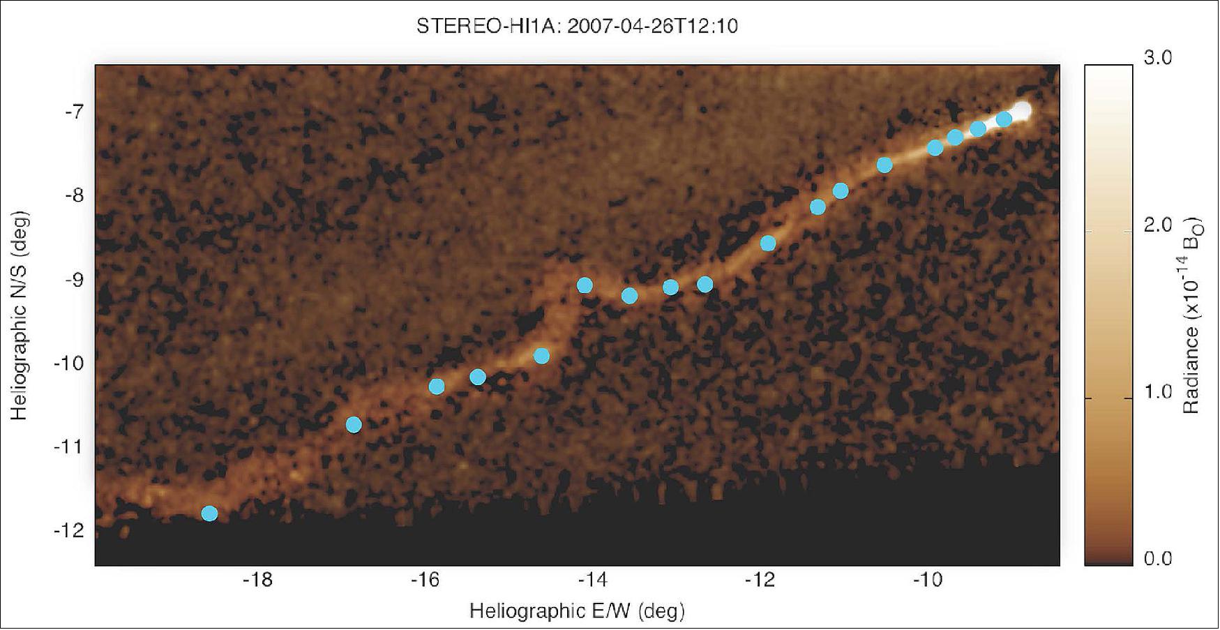
• Oct. 13, 2015: A team of scientists led by the heliophysics group at SwRI (Southwest Research Institute) in Boulder, CO has used observations of Comet Encke’s tail using NASA’s STEREO. The study revealed that the solar wind flows through the vacuum of interplanetary space much as the wind blows on Earth: not smoothly, but with gusting turbulence and swirling vortices. That turbulence can help explain two of the wind’s most curious features: its variable nature and unexpectedly high temperatures. 39) 40)
- “The solar wind at Earth is about 70 times hotter than one might expect from the temperature of the solar corona and from how much it expands as it crosses the void,” said Dr. Craig DeForest, a solar physicist at SwRI in Boulder, CO, and lead author on the study. “The source of this extra heat has been a mystery of solar wind physics for several decades.”
- There is much that is conclusively known about the solar wind: It is made of a sea of electrically-charged electrons and ions and also carries the interplanetary magnetic field along for the ride, forging a magnetic connection between the sun and Earth and the other planets in the solar system. There is no consensus, however, on what powers the wind's acceleration, especially when it is traveling at its fastest speeds. Complicating the search for such understanding are two of its most distinctive characteristics: The solar wind can be highly variable, meaning that measurements just short times or distances apart can yield quite different results. It is also very, very hot—remarkably so.
- The new study helped explain these characteristics using the heliospheric imager onboard STEREO. The scientists studied the movements of hundreds of dense chunks of glowing ionized gas within the ribbon of Comet Encke’s tail, which passed within STEREO’s field of view in 2007. Fluctuations in the solar wind are mirrored in what is seen in the tail, so by tracking these clumps, scientists were able to reconstruct the motion of the solar wind, catching an unprecedented look at the turbulence.
- Identifying this turbulence in the solar wind has the potential to solve the mystery of how the solar wind gets so hot. Based on the intensity of the turbulence researchers saw, they calculated that the energy available from turbulence is more than ten times what would be required to heat the solar wind to observed temperatures.
- For years, scientists have taken direct measurements of the solar wind — known as in situ measurements, which are captured as the solar wind passes over one of the dozens of satellites carrying the appropriate instruments. Most of these satellites observe the sun from a vantage point similar to that of Earth. STEREO-A, however, orbits the sun in a slightly smaller and faster orbit than Earth, meaning it moves around the sun farther and farther from Earth over time. So, in addition to the images of Comet Encke as it streamed past in April 2007, STEREO-A also provides us with in situ solar wind measurements from a unique perspective.
- On the other hand, the solar wind is notoriously hard to study remotely—that is, with measurements from afar. Its particles flow at 250 miles per second, and they are so dispersed that interplanetary space at Earth’s orbit has about a thousand times fewer particles in one cubic inch of space than the best laboratory vacuum on Earth.
- This solar wind dominates the space environment within our solar system and travels well past Pluto, creating a huge bubble known as the heliosphere. Closer to home, the solar wind also interacts with Earth’s magnetic field, sometimes initiating changes in near-Earth space that can disrupt our space technology or cause auroras. So scientists needed to come up with a way to look at something that’s invisible—and that’s where Comet Encke came in.
- Using the images from STEREO-A, scientists tracked 230 different features as they weaved through Comet Encke’s tail over the course of about 9.3 million miles of its journey around the sun. They then compared these motions to how they would expect solid objects to orbit around the sun, finding evidence that these gas clumps were being picked up by drag against the solar wind. They found that, though the gas clumps moved more or less randomly on smaller scales, they exhibited clear patterns on the scale of about 300,000 miles, indicating large-scale swirling eddies are mixing the solar wind—and possibly heating it as well.
• July 16, 2015: The STEREO project received first images in over three months from the STEREO-A spacecraft on July 11, 2015. The three-month safe mode period was necessary because of the geometry between Earth, the sun, and STEREO-A. STEREO-A orbits the sun as Earth does, but in a slightly smaller and faster orbit. The orbit ensured that over the course of years, Earth and the spacecraft got out of sync, with STEREO-A ending up on the other side of the sun from Earth, where it could show us views of our star that we couldn’t see from home. Though the sun only physically blocked STEREO-A from Earth’s line of sight for a few days, STEREO-A was close enough to the sun—from our perspective — that from March 24 until July 8, the sun interfered with STEREO-A’s data transmission signal, making it impossible to interpret. 41)
- As STEREO-A kept orbiting, it eventually made its way far enough from the sun to come out of this transmission dark zone. In late June, the STEREO-A team began receiving status updates from the spacecraft, confirming that it had made it through its long safe-mode journey unharmed.
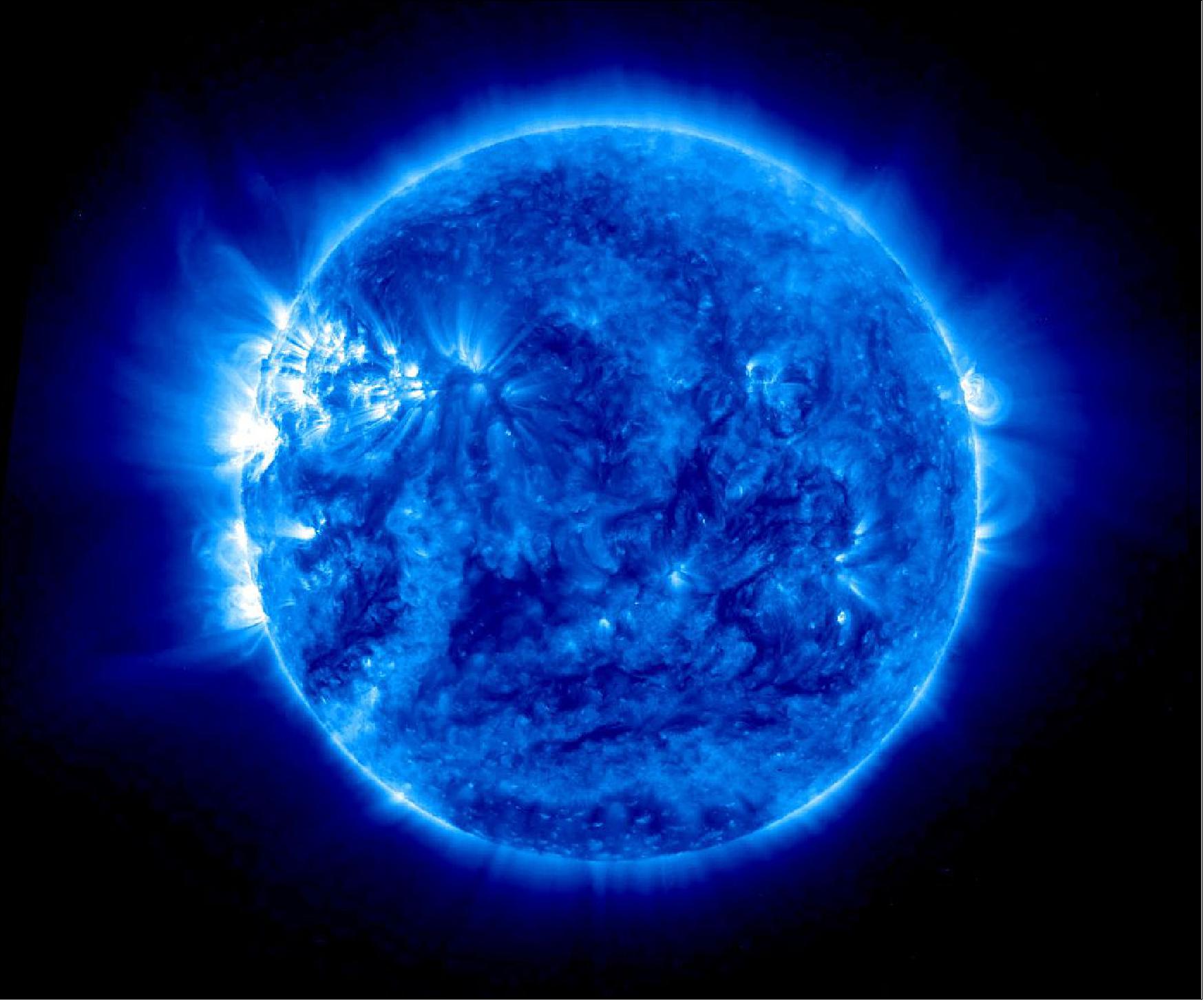
- While it was in safe mode, STEREO-A’s radio wave instrument collected and stored data almost continuously for four months. On July 9, 2015, the STEREO team began turning on the solar wind and particle instruments, and over the weekend they powered up the imaging instrument. The image of Figure 30 is from the Extreme Ultraviolet Imager, which collects images in several wavelengths of light that are invisible to the human eye. The imaging instrument suite also has two coronagraphs and a heliospheric imager, which are useful for tracking the speed and shape of the giant clouds of gas expelled by the sun called CMEs (Coronal Mass Ejections). By triangulating the views from STEREO and solar observatories closer to Earth such as the joint ESA and NASA SOHO (Solar and Heliospheric Observatory), scientists can create a full 3-dimensional model of these CMEs.
• July 2015: The STEREO mission is approved by NASA to continue planning against the current budget guidelines. NASA will work with the mission as the attempts to regain contact with the STEREO-B satellite continue through the end of 2015. Any changes to the guidelines will be handled through the budget formulation process. The STEREO mission will be invited to the 2017 Heliophysics Senior Review. 42)
- The STEREO mission is based on twin spacecraft providing new perspectives on the Sun and the heliosphere from multiple longitudinal viewpoints near 1 AU. The mission completed its prime phase in January 2009 after nearly two years of operations. The STEREO spacecraft were launched on a single Delta II vehicle in October 2006 and inserted into heliocentric orbits in December 2008 (Ahead) and January 2009 (Behind). The two spacecraft drift away from the Sun-Earth line by 22° per year. They were in opposition in February 2011 and approached the Sun-Earth line on the far side of the Sun until superior conjunction (2015 January–July). The mission is now at superior conjunction.
• June 2015: Both STEREO spacecraft carry a combination of remote sensing and in situ instruments (SECCHI, IMPACT, PLASTIC and SWAVES). The STEREO mission is one of the missions which provide real-time data that are used directly in the NOAA Space Weather Forecast Office. Each of the STEREO instrument teams involves US as well as European scientists and one of the STEREO instruments (SWAVES) has both US and French PIs. Data from the mission are freely available via the STEREO Science Center and the instrument team websites. 43)
- The strong potential of the STEREO mission is to be able to study and understand the initiation, propagation and evolution of space weather events across the heliosphere. The combination of several remote sensing instruments (EUV imager, coronagraphs, heliospheric imager) allows the follow of the propagation of CMEs (Coronal Mass Ejections) from their onset at the Sun to 1 AU and in combination with in situ experiments to measure the parameters (velocity, temperature, density...) of the associated perturbations at 1 AU. Observations from STEREO from two different vantage points in combination with e.g., observations from SOHO/LASCO provide unique input for determining the conditions of the solar wind and perturbations at the encounter of other planets of the solar system as well as at the boundaries of the heliosphere. The STEREO observations are also used for space weather applications at the NOAA Space Weather Forecast Office.
- The two spacecraft are currently at superior conjunction after having probed since launch a complete range of angles with the Sun-Earth axis. A major current concern is the potential loss of STEREO-B. Thus the proposal presented two versions for the science of the extended mission and for the budget (in case STEREO-B is recovered or not). In the context of the senior review, the discussion of the extension and the evaluation was done considering the two options.
- STEREO science strengths: The combination of remote sensing and in situ instruments on STEREO, the new possibilities of observations provided by the heliospheric imagers and the unique 3D perspective of the phenomena provided by the mission led to new and sometimes intriguing results in the field of solar and heliospheric physics. The unique vantage points and complete instrumentation have provided and will continue to provide significant capabilities to address the 10 discussed in the proposal.
- Important results were obtained since the last review on the large scale structures of CMEs (using multiple point measurements of ICMEs), the propagation of CMEs in the IP medium (interaction with the ambient medium, with other CMEs, deflection), and on the source and propagation of solar energetic particles [unexpected results were obtained on the angular extension at which SEPs (Solar Energetic Particles) are observed]. New results were also obtained on the production of radio bursts from electron beams or shocks using the TDS mode of SWAVES.
- STEREO far side observations combined with Earth side observations provide new views on the connections between CMEs, EUV waves, shocks and the occurrence of sympathetic events. Far side observations are also crucial to understand the lifetime of active regions, coronal holes as well as to estimate the amount of open flux from coronal holes.
- STEREO observations with PLASTIC and IMPACT also provided interesting results on interstellar pickup ions and allow the building of longitudinal surveys of He+, O+ and Ne+, which are quite useful to determine the direction and the speed of the flow of interstellar neutrals. New and important results were also obtained on the dust in the inner heliosphere (decrease with time of the nano dust flux as the solar cycle evolves).
- The science return from the STEREO mission’s instruments has been excellent in the past years. Future scientific returns of the mission by itself have been evaluated in the hypothesis of a one spacecraft and two spacecraft mission. The panel has found that if STEREO-B is recovered, the contribution of the mission promise to be compelling (mean grade 8/10) for overall scientific merit although in the case of a single STEREO spacecraft the mean grade is down to 7 (excellent but less compelling).
- The STEREO mission has a strong impact in the Heliophysics Great Observatory (even in the case of the loss of STEREO-B). Even with only one spacecraft, the mission provides unique data (obtained at a unique vantage point) that largely contributes to our understanding of the whole heliosphere and brings a valuable contribution for many solar, planetary and interplanetary missions. This is revealed in the grade and ranking given to STEREO in the context of HSO (Heliophysics System Observatory) contributions (median rate 8/10 for both one or two spacecraft missions, e.g., future contribution promise to be compelling).
• November 7, 2014: Communications with the STEREO Behind spacecraft were interrupted on October 1, 2014 immediately after a planned reset of the spacecraft performed as part of a test of solar conjunction operations. There have been no successful communications since then, though attempts to recover the spacecraft continue. 44)
The events are explained that led up to the loss in communications, and the activities that have been carried out in an attempt to recover the spacecraft. As explained below, initial indications are that a series of problems in the guidance and control system led to the anomaly.
Because both STEREO spacecraft are now on the far side of the Sun, new modes of operations needed to be developed to protect the HGA (High Gain Antenna) from the elevated temperatures caused by pointing near the Sun, and also to put the spacecraft into an autonomous safe mode for the period when solar radio interference will prevent communication. Collectively, these new modes are known as solar conjunction operations. A series of tests were conducted to make sure that the spacecraft perform as planned with these new operations modes. The first spacecraft to be affected was STEREO Ahead, and these tests were all carried out successfully on that spacecraft. On August 20, 2014, Ahead entered the first phase of the solar conjunction period, which will continue in its various phases until early 2016.
On September 27, 2014, the STEREO Behind spacecraft began one of the test sequences that had already been carried out on Ahead. This sequence was designed to test putting the Behind spacecraft into the safe mode that it will be in during the solar radio interference period, and then to bring it back out again into normal operations. One part of this test was to observe the firing of the spacecraft hard command loss timer, which resets the spacecraft if no commands are received after three days. The purpose of this is to correct any problems that might be preventing the spacecraft from receiving commands from the ground. While the spacecraft is out of contact on the far side of the Sun, this reset will occur every three days.
On October 1, 2014, the hard command loss timer on the spacecraft was observed to fire at the expected time, causing the spacecraft to reset. However, the radio signal observed on the ground immediately after the reset was very weak, and then quickly faded away. That was the last signal received from the Behind spacecraft. The only information that the project has is from the limited telemetry extracted from the radio signal just before and just after the reset. Here is what is known so far:
- The telemetry from just before the reset shows no problems with the spacecraft.
- Only three packets could be successfully recovered from the very faint telemetry received just after the reset. These data show that the IMU (Inertial Measurement Unit) was powered on. The IMU uses ring laser gyros to measure the rotational rates and orientation of the spacecraft. At this stage of the mission, it's normally powered off. The IMU being powered on indicates that the Star Tracker, which normally provides this information, had not acquired a set of guide stars in a predetermined length of time.
- This is not unexpected — there have been other occasions when it took the Star Tracker several minutes, or even a few days, to start determining the spacecraft orientation based on star images. In fact, on September 28, as part of the same test sequence, the spacecraft was reset, and it took 12 minutes for the Star Tracker to start providing an attitude solution. When the Star Tracker is offline, the spacecraft will automatically turn on the IMU to provide rotational rate information.
- The lack of data from the Star Tracker would explain why the radio signal after the reset was initially very weak and then faded away. Without the Star Tracker, the high gain antenna cannot be properly pointed at Earth, resulting in the initial faint signal, which then drifted even further so that the signal was lost completely.
- However, the limited telemetry received after the spacecraft reset also indicates that one of the laser gyros in the IMU had failed, and was providing bad data to the attitude control system. Thus, two simultaneous failures had occurred in the attitude control system — the Star Tracker and the IMU — and the ability of the spacecraft's guidance and control electronics to cope with multiple failures is limited.
With only that limited amount of information, it's unclear what happened next. If the spacecraft managed to recognize that the IMU had an anomaly, it would have disabled it, and fallen back on the only system left for determining orientation, the solar aspect sensors. There are five solar aspect sensors on the spacecraft, among them covering the full sky. With just these sensors operating, the Behind spacecraft should at least have kept itself well enough pointed to keep the solar panels pointed at the Sun, and maintain power on the spacecraft.
However, if the spacecraft did not detect that the IMU was providing bad data, it may have fired its thrusters to stop the roll that it thought it was in. With bad data coming from the IMU, instead of stabilizing the spacecraft, this would have sent it into a spin about its principal axis of inertia. The solar panels may have then stopped getting enough sunlight to keep the spacecraft powered, draining the batteries and shutting the spacecraft down.
Attempts to reestablish communications with the STEREO Behind spacecraft are ongoing. Since the loss of communications on October 1, the operations team has been broadcasting commands designed to correct a number of possible scenarios as to why no communications have been heard. Some of these commands are intended to aid the Star Tracker come back online. Other commands are intended to reactivate the spacecraft transmitter, in case it somehow got deactivated. Commands have also been broadcast to disable the failed IMU. So far, none of these activities have been successful. Attempts were also made to detect the signal from Behind with the Green Bank 100 m radio telescope, without success.
Even if the STEREO Behind spacecraft is currently drifting without power, not all hope is lost. A similar situation occurred with the SOHO mission in 1998, where the spacecraft ended up in spin with the solar panels pointed away from the Sun. As SOHO continued to move along in its orbit, it eventually got to a point where sunlight started falling on the solar panels again. The operations team (with a considerable amount of effort) was able to recover the spacecraft into operating mode. Now, sixteen years later, SOHO is still providing valuable data to the solar and space weather communities.
Once communications are restored and the anomaly resolved, the operational plan for exiting the solar conjunction testing will continue to return the Behind observatory back to nominal science data collection as soon as safely possible.
Launched in 2006, the STEREO mission achieved its prime science goals within the two-year prime mission, but continues to explore solar and heliospheric activity through the current solar maximum and beyond. STEREO Ahead continues to operate nominally, and is currently providing our only views of the far side of the Sun.
• July 3, 2014: The orbits of the two STEREO spacecraft are now nearing each other once again, this time on the other side of the sun. During this period when the sun blocks Earth's view — a geometrical position known in astronomy as a superior conjunction — radio receivers on Earth will not be able to distinguish STEREO's signal from the sun's radiation. Communication with the spacecraft will cease and the satellites will both go into safe mode without collecting data for a time. This will happen for STEREO-Ahead from March 24 to July 7, 2015. STEREO-Behind will be in superior conjunction from Jan. 22 to March 23, 2015. At least one spacecraft, therefore, will always be collecting data. 45)
- Before this occurs, the heating from the sun will also begin to affect – though not shut down — data collection. From wherever they are in space, the STEREO spacecraft aim their antenna toward Earth to send down data. This position puts the antenna fairly close to pointing at the sun, exposing the instruments to more heat than it can safely bear. The antenna can be adjusted to point in different directions, but the signal coming to Earth will be much fainter and won't allow for as much data to be downloaded. This antenna adjustment will begin on Aug. 20, 2014, for the STEREO-Ahead spacecraft and on Dec. 1, 2014, for STEREO-Behind.
- During this phase, STEREO instruments will continue to run 24 hours a day, but they will gather lower-resolution data than usual. Some of this data will be downloaded whenever STEREO can link up with an Earth receiver. The rest of the data will be stored on board to be downloaded when the spacecraft reach a more auspicious geometrical position in early 2016.
- To test for this off-pointing from the sun, STEREO-Ahead will undergo tests and not be collecting data from July 6-12, 2014. The same tests will be performed on STEREO-Behind from Sept. 29 – Oct. 6, 2014.
- Throughout this entire phase until 2016, at least one STEREO spacecraft will be capturing data at any one time, so scientists will have an uninterrupted record of events on the sun to coordinate with the observations of solar telescopes on the Earth side. Real time monitoring of the sun, its flares and coronal mass ejections – information used by NOAA (National Oceanic and Atmospheric Administration) to help forecast space weather — will also continue via a fleet of NASA spacecraft closer to Earth.
• January 2014: Both STEREO spacecraft are currently performing as expected and taking science data on a regular basis. 46)
Relevancy to the heliophysics research objectives: STEREO is very much a ‘Great Observatory’ mission, especially in the extended phase. Its relevance to other solar, as well as planetary and interplanetary, missions is unquestionably high. It spans from near Earth solar and interplanetary (i.e., SOHO, SDO, ACE, WIND, and IBEX) to planetary (i.e., Messenger, Venus Express, Mars Express, and MAVEN). As much as STEREO will benefit from SOHO, ACE and Wind, those missions will benefit from STEREO’s complement of instruments and side view perspective. The planetary missions will get three times the opportunity to have conjunctions and oppositions with well instrumented spacecraft than they do now, when only near Earth instrumentation is available. By utilization of new results from the Van Allen Probes, it is expected that there will be new advances in understanding of the coupling of solar generated variability in radiation, fields, and particles that will enable advanced predictive capability for space weather research. 47)
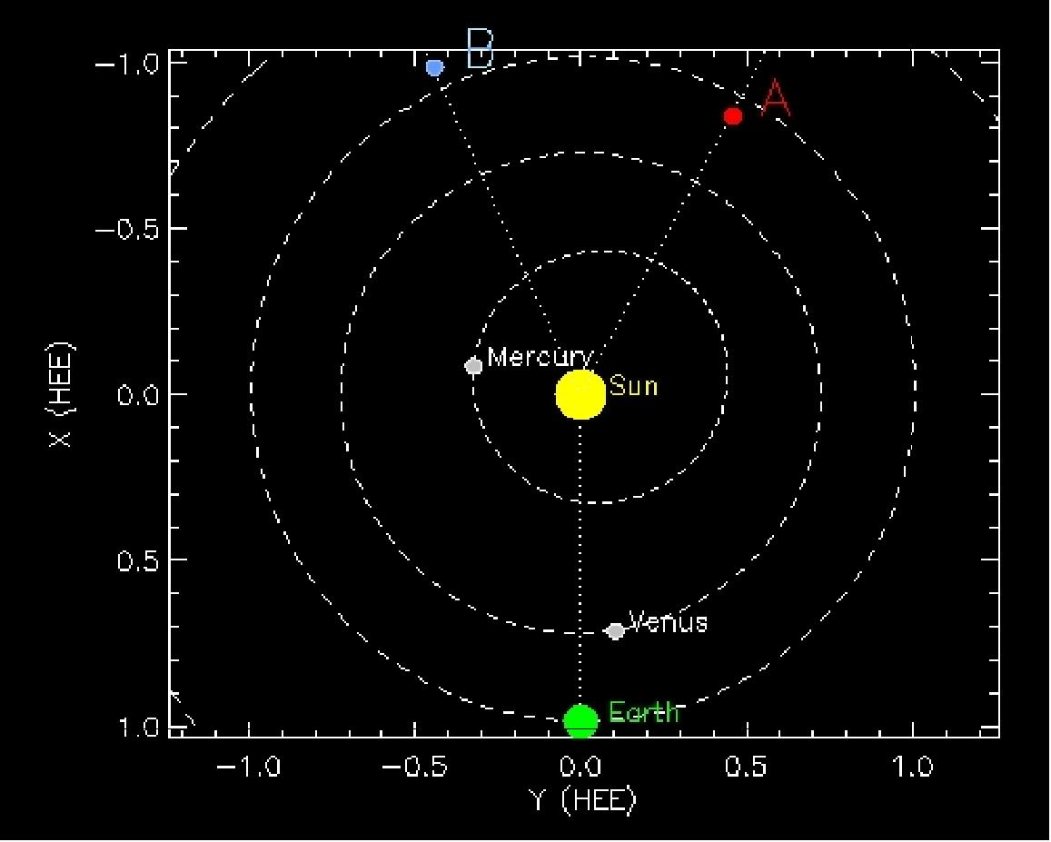
• Nov. 26, 2013: The STEREO spacecraft is monitoring Comet ISON as it approaches the sun. 49)
• The two STEREO spacecraft and their payloads are operating nominally in February 2013. 50)
• On October 26, 2012, the twin STEREO spacecraft completed their 6th anniversary on orbit. 51)
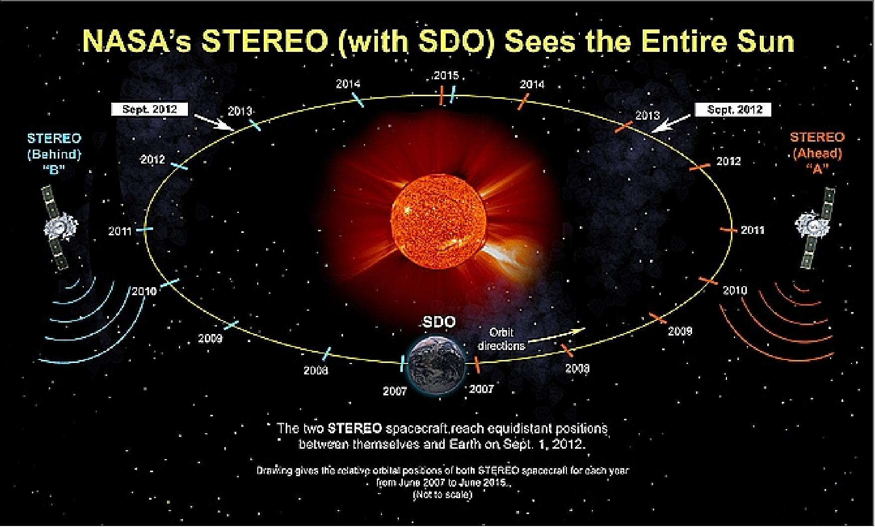
Legend to Figure 33: On Sept. 1, 2012, the two spacecraft and and the Solar Dynamics Observatory (at Earth) formed an equal-sided triangle, with each observatory providing overlapping views of the entire sun. By providing such unique viewpoints, STEREO has offered scientists the ability to see all sides of the sun simultaneously for the first time in history, augmented with a view from Earth's perspective by NASA's Solar Dynamics Observatory (SDO). In addition to giving researchers a view of active regions on the sun before they even come over the horizon, combining two views is crucial for three-dimensional observations of the giant filaments that dance off the sun's surface or the massive eruptions of solar material known as CMEs (Coronal Mass Ejections).
• Observation of a very large CME from the far side of the sun: On July 23, 2012, a massive cloud of solar material erupted off the sun's far side, zooming out into space, passing one of NASA's STEREO spacecraft along the way. Using the STEREO data, scientists at NASA's Goddard Space Flight Center in Greenbelt, MD, clocked this giant cloud, known as a CME (Coronal Mass Ejection), as traveling between 2900 and 3500 km/s as it left the sun. Measuring a CME at this speed, traveling in a direction safely away from Earth, represents a fantastic opportunity for researchers studying the sun's effects. 52)
On July 23, STEREO-A lay — from Earth's perspective — to the right side and a little behind the sun, the perfect place for observing this CME, which would otherwise have been hard to measure from Earth. The SOHO (Solar Heliospheric Observatory) spacecraft, an ESA and NASA mission, also observed the CME. It is the combination of observations from both missions that helps make scientists confident in the large velocities they measured for this event.
STEREO-A could observe the speed of the CME as it burst from the sun, and it provided even more data some 17 hours later as the CME physically swept by – having slowed down by then to about 1200 km/s. STEREO has instruments to measure the magnetic field strength, which in this case was four times as strong as the most common CMEs. When a CME with strong magnetic fields arrives near Earth, it can cause something called a geomagnetic storm that disrupts Earth's own magnetic environment and can potentially affect satellite operations or in worst-case scenarios induce electric currents in the ground that can affect power grids.
The event also pushed a burst of fast protons out from the sun. The number of charged particles near STEREO jumped 100,000 times within an hour of the CME's start. When such bursts of solar particles invade Earth's magnetic field they are referred to as a solar radiation storm, and they can block high frequency radio communications as used, for example, by airline pilots. Like the CME, this SEP (Solar Energetic Particle) storm event is also the most intense storm ever measured by STEREO. While the CME was not directed toward Earth, the SEP did – at a much lower intensity than at STEREO – affect Earth as well, offering scientists a chance to study how such events can widen so dramatically as they travel through space.
In the case of the July 22, 2012 event, three spacecraft offered data on the CMEs: the two STEREO spacecraft and SOHO (Solar and Heliospheric Observatory) of ESA and NASA. SOHO lies between Earth and the sun, while the two STEREO spacecraft have orbits that for most of their journey give views of the sun that cannot be had from Earth. Each spacecraft observed the CMEs from a different angle, and together they could help map out a three-dimensional image of what happened. 53) 54)
With the fastest CME measured by the STEREO spacecraft so far (the CME was travelling over 2900 km/s as it left the sun, but not directed toward Earth) represented a fantastic opportunity for researchers studying the sun's effects. Now, a paper in Nature Communications, published on March 18, 2014, describes how a combination of events worked together to create these incredible speeds. The authors suggest this extreme event was due to the interaction of two CMEs separated by only 10 to 15 minutes. 55) 56)
Two Examples of Solar Super Flares in History 57) 58)
- The most powerful solar flare of the last 500 years was the first flare to be observed, on September 1, 1859, and was reported by British astronomer Richard Carrington. The event is named the Solar storm of 1859, or the "Carrington event". A flare was visible to the naked-eye and produced stunning auroras down to tropical latitudes such as Cuba or Hawaii, and set telegraph systems on fire. The flare left a trace in the Greenland ice in the form of nitrates and beryllium-10, which allow its strength to be measured today. The magnetic field at Earth measured 110 nT during the Carrington event of 1859.
- So far, the most powerful flare on record in the space age occurred on Nov. 4, 2003 (the flare started on October 29, 2003 and is also referred to as the Halloween storm), during the last solar maximum. It was so powerful that it saturated the detectors of the GOES spacecraft. They cut-out at X17, and the flare was later estimated to be about X45. A powerful X-class flare like that can create long lasting radiation storms, which can harm satellites, and even give airline passengers flying near the poles small radiation doses. X flares also have the potential to create global transmission problems and world-wide blackouts. The seriousness of an X-class flare pointed at Earth is why NASA and NOAA constantly monitor the sun.
A few days later on Nov. 4, 2003 one of the most powerful X-ray flares swamped the sensors of dozens of satellites, causing satellite operations anomalies -but no aurora. Extensive satellite problems were reported due to the Halloween storm, including the loss of the ADEOS-2 spacecraft of JAXA (launch Dec. 14, 2002).• The two STEREO spacecraft and their payloads are operating nominally in 2012 (Ref. 6).
• On Oct. 25, 2011, the two STEREO spacecraft celebrated their 5th on-orbit anniversary. Over the last five years, each STEREO spacecraft has moved to a position in its orbit where it can capture side-view images of anything the sun sends our way.
In the coming months, the two satellites will keep moving further away from Earth, lining up on the far side of the sun in 2015 and continuing on their journey until they are once again on Earth's side. During the trip, scientists will use STEREO observations to calibrate their techniques to monitor what's happening on the far side of the sun by tracking the sound waves that roll through the sun's interior – a technique called helioseismology. 59)
• The first complete image of the solar far side, the half of the sun invisible from Earth, was taken on June 1, 2011. The composite image was assembled from NASA's two STEREO probes. The STEREO-A data is shown on the left half of image and the STEREO-B data on the right of Figure 34. The image is aligned so that solar north is directly up. The seam between the two images is inclined because the plane of Earth’s — and STEREO's — orbit, known as the "ecliptic", is inclined with respect to the sun's axis of rotation. The data was collected by the SECCHI instrument suite. 60)
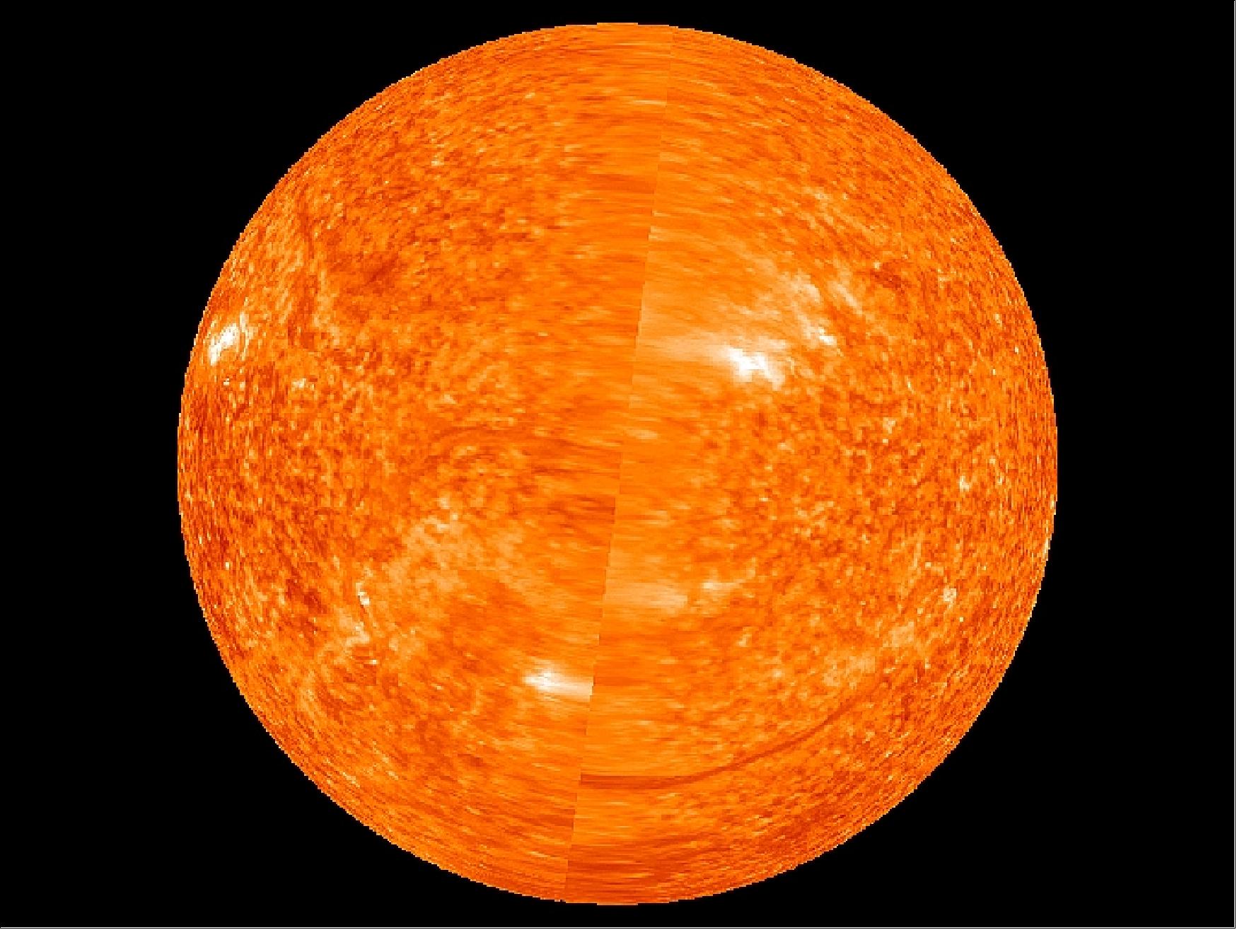
• On Feb. 6, 2011, NASA's twin STEREO probes moved into position on opposite sides of the sun (180º apart, Figures 35 and 36) providing a view of the entire sun - front and back (this is the first time in history to see both sides of the sun simultaneously). This permits the project to view solar activity in its full 3-dimensional extent. 61)
Until now, the project had to wait about 2 weeks until the rear side active regions of the sun rotated into view on the front side. But no longer. On average the sun rotates in about 27 days – faster at the equator and slower at the poles. The new far side data will allow much faster detection of solar storms which in turn will enable faster predictions of space weather which potentially can severely impact sensitive technological infrastructure on Earth and throughout the solar system. 62)
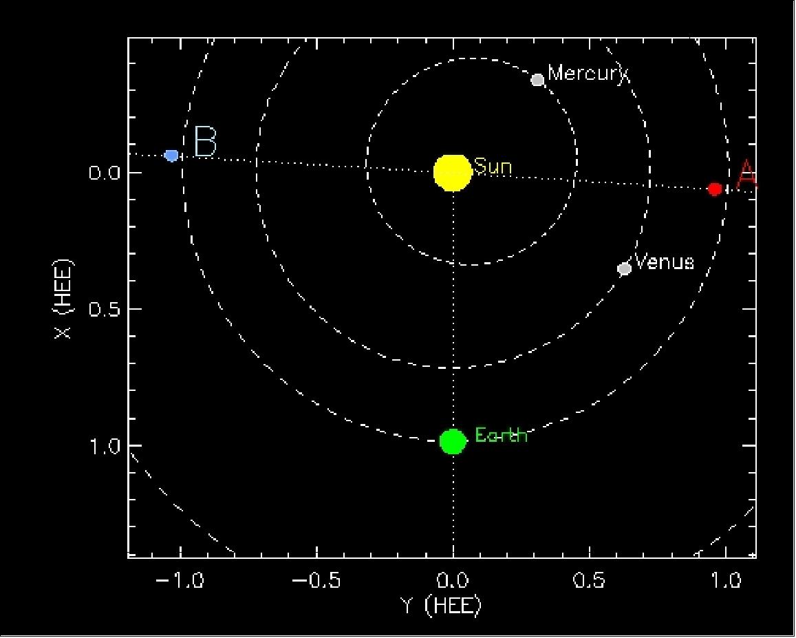
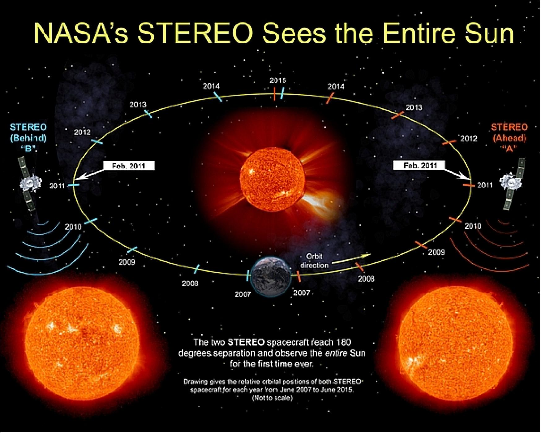
The STEREO mission constellation is operating nominally in 2010 in its 4th year on orbit (Ref. 4) and 6).
• The twin STEREO spacecraft (called “Behind” and “Ahead” denoting their relative positions in space), now almost 120º apart, captured this large and dramatic prominence eruption over about a 30-hour period between Sept. 26-27, 2009. 63)
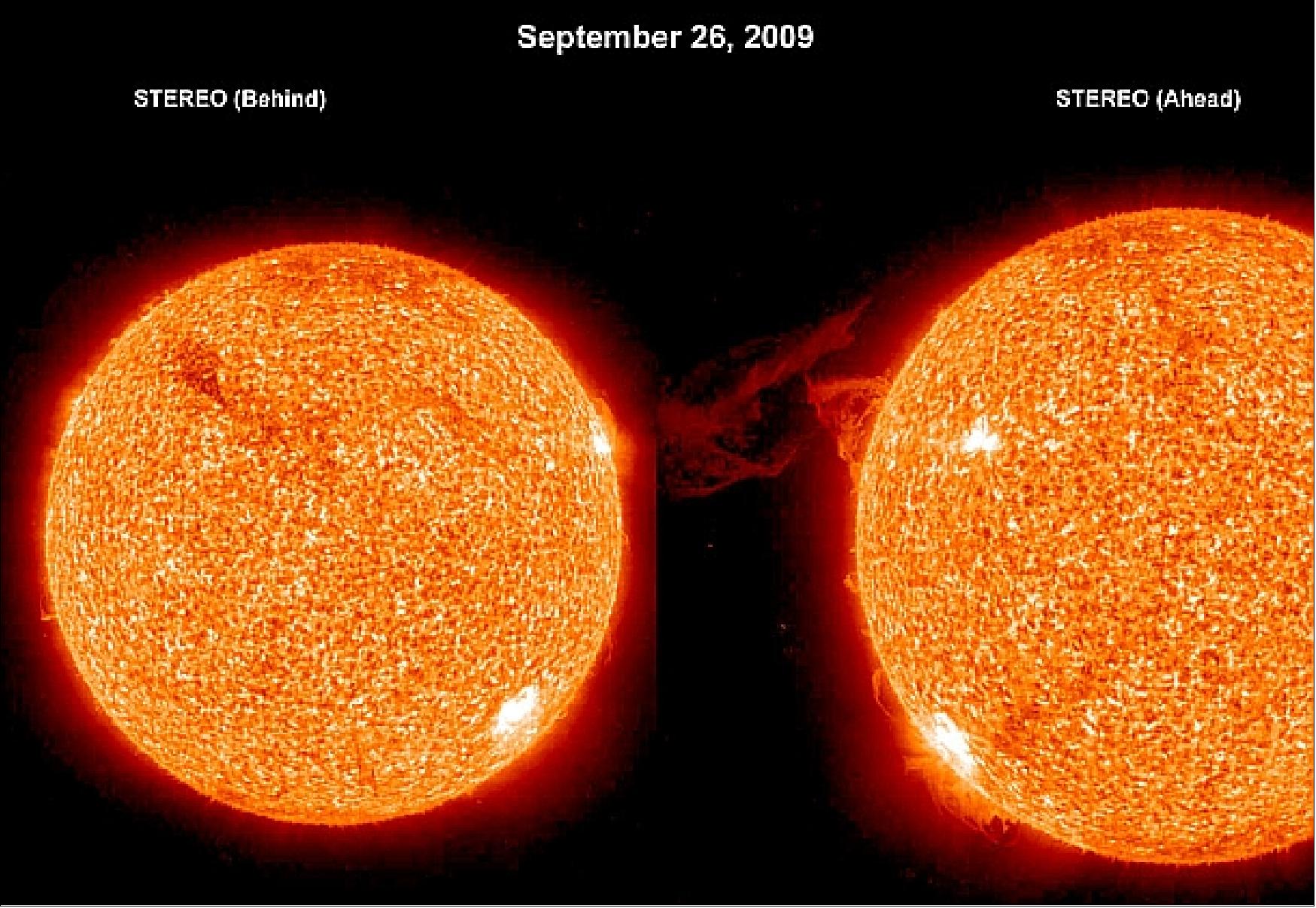
• In February 2009, a huge CME (Coronal Mass Ejection) occurred on the sun which was witnessed by the twin spacecraft. The angular position of STEREO-B was directly over the blast site while STEREO-A was stationed at right angles — a perfect geometry for cracking the phenomenon on the sun known as the "solar tsunami." The scale of a solar tsunami is so staggering that solar physicists doubted their senses in the past when observing such an event. It rose up higher than Earth itself and rippled out from a central point in a circular pattern millions of kilometers in circumference. Skeptical observers suggested it might be a shadow of some kind—a trick of the eye—but surely not a real wave. 64) 65) 66)
The twin STEREO spacecraft confirmed their reality in February 2009 when sunspot 11012 unexpectedly erupted. The blast hurled a billion-ton cloud of gas (a CME) into space and sent a tsunami racing along the sun's surface. STEREO recorded the wave from two positions separated by 90º, giving researchers an unprecedented view of the event which is termed as a fast-mode MHD (Magnetohydrodynamic) wave. The one STEREO saw reared up about 100,000 km high, and raced outward at 250 km/s packing as much energy as 2400 megatons of TNT (1022 joule).
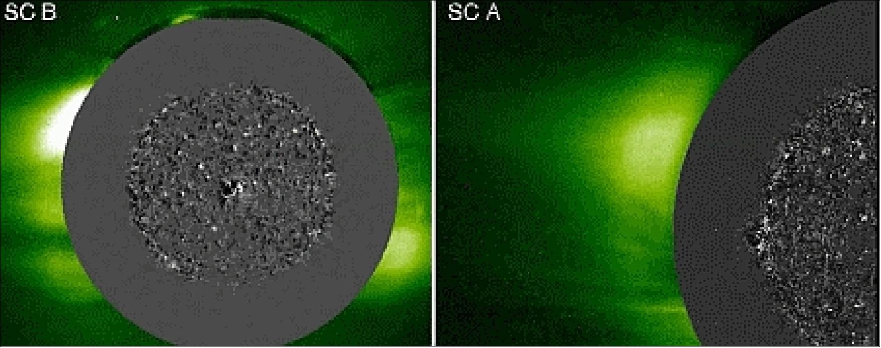
Legend to Figure 38: The gray part of the animation has been contrast-enhanced by subtracting successive pairs of images, resulting in a "difference movie."
Solar tsunamis were discovered in 1997 by the SOHO (Solar and Heliospheric Observatory) of ESA. In May 1997, a CME came blasting up from an active region on the sun's surface, and SOHO recorded a tsunami rippling away from the blast site.
• The continuous progression of the two STEREO spacecraft orbits in the ecliptic plane is widening the observation capability of the sun. As of January 2009, more than 270º of solar longitude can be observed (Figure 10 and 39). The sun spins on its axis once every 25 days, so over the course of a month the whole sun does turn to face Earth, but a month is not nearly fast enough to keep track of events. 67) 68)
Since the sun spins counterclockwise in its orbit, STEREO-B gets a sneak preview of sunspots and coronal holes before they turn to face Earth-a boon for forecasters. In early 2009, STEREO-B enjoys a 3-day look-ahead advantage over Earth-based observatories. This has allowed researchers to predict geomagnetic storms as much as 72 hours earlier than ever before. On several occasions in late 2008, STEREO-B spotted a coronal hole spewing solar wind before any other spacecraft did.
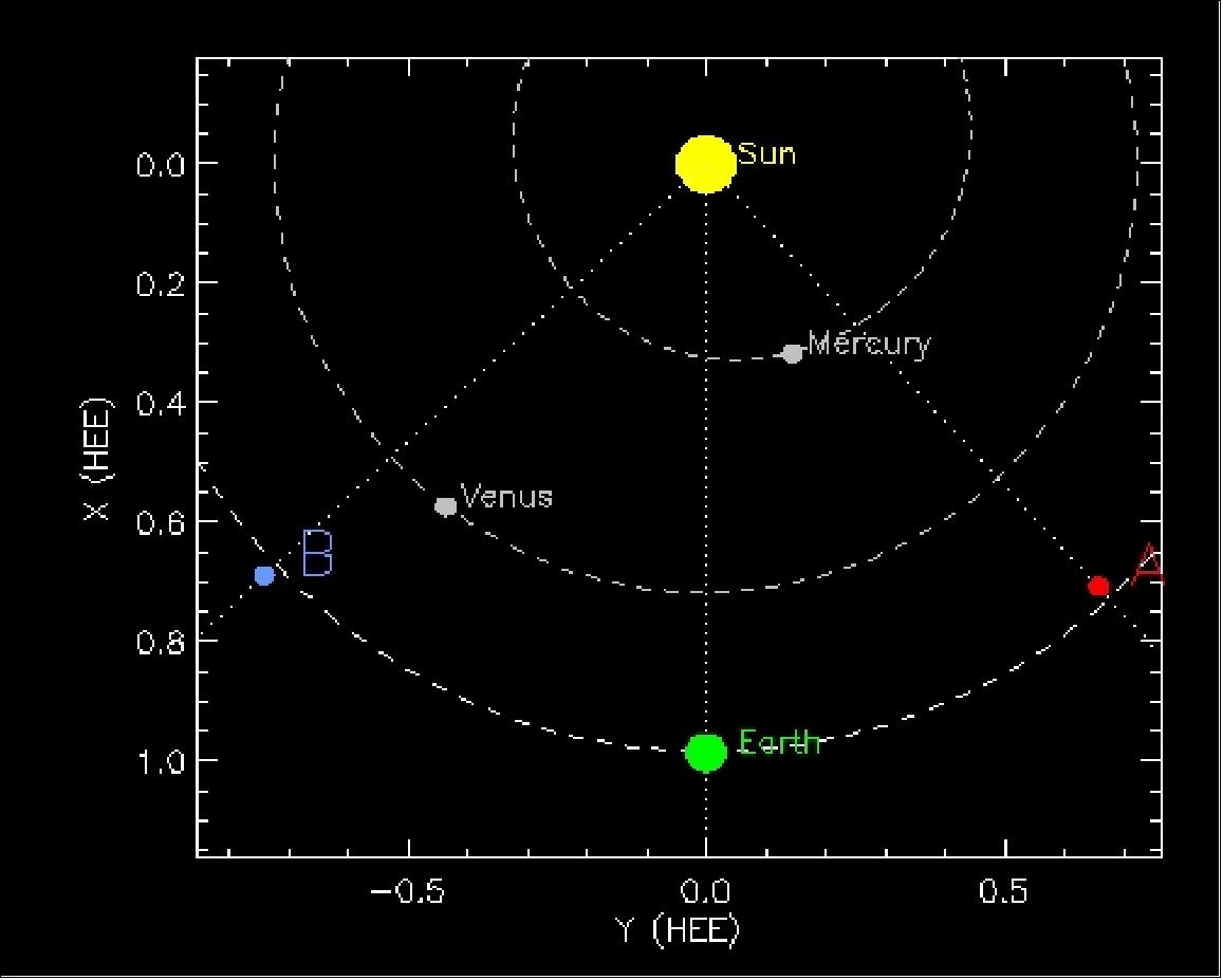
• On April 23, 2007, the twin spacecraft have made the first three-dimensional images of the Sun. The new view will greatly aid scientists' ability to understand solar physics and thereby improve space weather forecasting. 70)
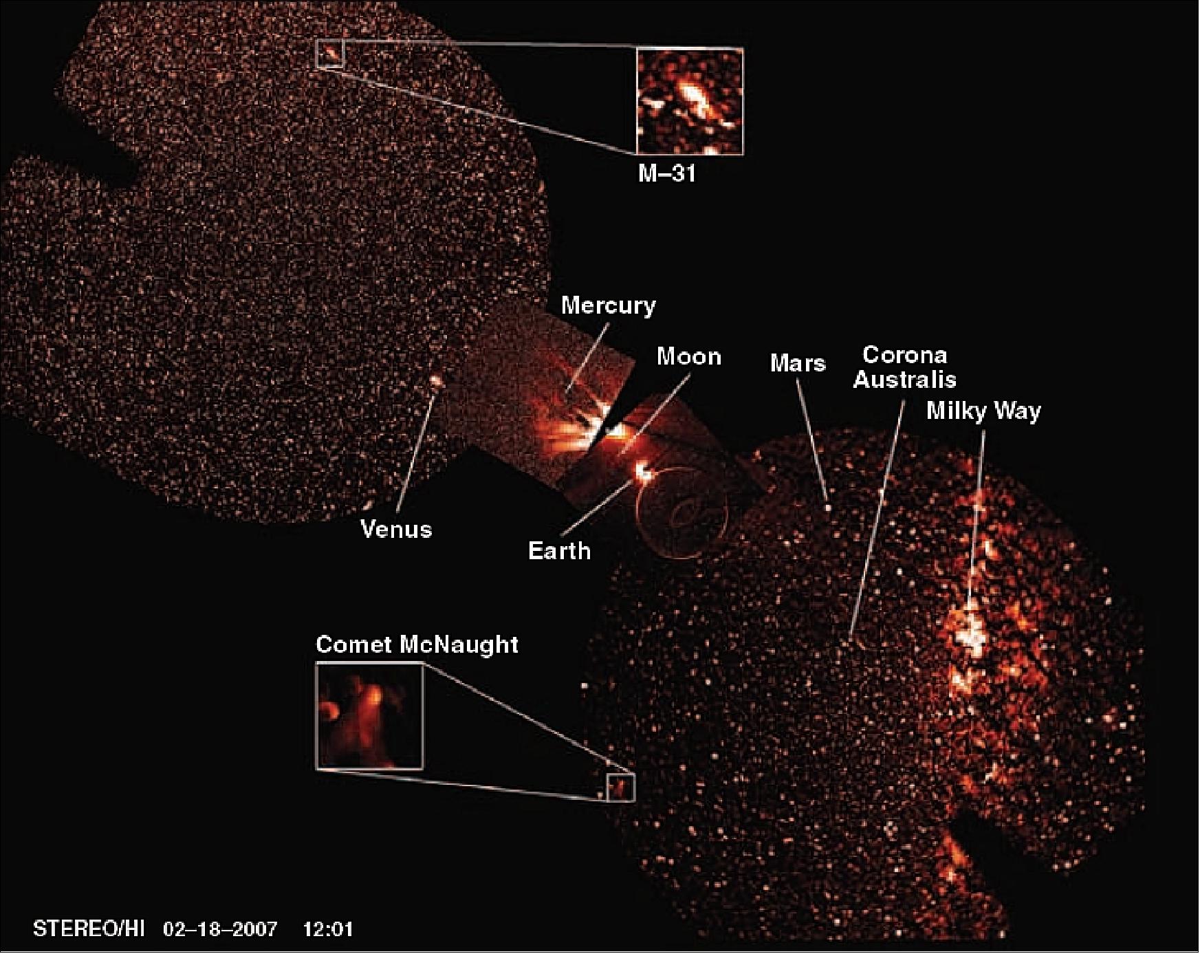
Legend to Figure 40: Literally half of the sky in a single view can be made by combining all of the coronagraph and HI images from the two STEREO spacecraft. The view covers the angular range from the Sun in the center out to ~90º in both directions along the ecliptic. Several planets as well as the Earth and Moon can be seen as can Comet McNaught. The Andromeda galaxy (M-31) can be seen at the top left, and the Milky Way is at the right (Ref. 8).
• With the second lunar swingby by the Behind spacecraft (STEREO-B) on January 21 2007, the STEREO mission entered into the main science phase of the mission. The two spacecraft have now escaped from Earth orbit and are in orbit around the Sun (to take on their mission orbits).
• The first sun observation images taken by the STEREO-A spacecraft were received on Dec. 4, 2006. The SECCHI instrument captured a very active region on the sun known as AR903 that produced a series of intense flares. A few days later during an unusually active solar period, the ”A” observatory captured images of a coronal mass ejection with one of SECCHI's two white-light coronagraphs.
• On Dec. 15, 2006, mission operations personnel at JHU/APL used lunar gravitational swingbys to alter the spacecraft orbits, redirecting the ”A” observatory to its orbit ”ahead” of Earth. STEREO-A flew past the moon at a distance of approximately 7,340 km. The STEREO-B spacecraft passed approximately 11,776 km above the lunar surface where gravity is slightly weaker. Although the ”B” observatory's orbit was slightly boosted, the spacecraft didn't undergo its full lunar gravitational assist until Jan. 21, 2007 when it re-encountered the moon. The spacecraft then came within approximately 8,818 km of the surface, swinging past the moon in the opposite direction of the ”A” spacecraft and into an orbit ”behind” Earth.
Sensor Complement (SECCHI, IMPACT, PLASTIC, SWAVES)
The sensor complement consists of four scientific instruments (two instruments and two instrument suites, with a total of 13 instruments per observatory). All STEREO instruments involve participation and collaboration of teams from a number of institutions. This applies to instrument design and development as well as to instrument operations, data sharing and analysis. 71)
The overall measurement strategy calls for:
• Imaging of the solar atmosphere and heliosphere from two perspectives simultaneously
• Tracking of disturbances in 3-D from their onset at the sun to beyond Earth's orbit
• Measurement of energetic particles generated by the disturbances
• Sampling of fields and particles in the disturbances as they pass Earth's orbit.
Phenomenon | Feature size resolved | Physical properties |
CMEs near the sun | 40, 000 km = 2x10⁻⁴ AU (6 min) | Density, velocity, internal structure, extent |
Flares | 2,000 km | Position, density, structure |
Moreton waves | 5,000 km | Wave front shape, velocity, underlying magnetic field |
Coronal loops | 2,000 km | Temperature, density, structure, deflection by waves |
Coronal streamers | 40,000 km | Distortion by CMEs, extent |
Coronal holes | 2,000 km | Footprint, spreading |
SEPs (Solar Energetic Particles) | 2 minutes | 3-D distribution function |
CMEs near Earth | 0.01 AU (images),1 minute (plasma) | Magnetic field, density, velocity, shape, extent, temperature |
Interplanetary shocks | 0.02 AU (5 seconds) | Extent, velocity, strength |
SECCHI (Sun-Earth Connection Coronal and Heliospheric Investigation)
SECCHI is an instrument suite, PI: Russell A. Howard of NRL. The instrument is named after one of the first solar physicists, namely A. Pietro Secchi (1818-1878), who used the new medium of photography to record solar eclipses. The overall objective is to study the 3-D evolution of CMEs from birth at the sun's surface through the corona and interplanetary medium to its eventual impact at Earth.
SECCHI consists of a suite of remote sensing instruments: an EUVI (Extreme Ultraviolet Imager), two white-light coronagraphs (COR1 and COR2), and an HI (Heliospheric Imager) package. The EUVI+COR1+COR2 devices are collectively referred to as SCIP (Sun Centered Imaging Package). The SEB (SECCHI Electronics Box) supports all of the SECCHI instruments. The total mass of the SECCHI instrument is 69.3 kg (SCIP=44.6 kg, HI= 11.3 kg, SEB= 9.2 kg), total power = 50 W. 72) 73) 74) 75)
Parameter | CCOR1 (Coronagraph1 imager) | OR2 (Coronagraph2 imager) | HI (Heliospheric Imager-1,-2) | EUVI (EUV Imager) |
Instrument type | Internally occulted Lyot coronagraph | Externally occulted Lyot coronagraph | Externally occulted coronagraph | EUV narrow-bandpass Ritchey Chretien telescope |
Observable | K-corona and CMEs | K-corona, F-corona and CMEs | K-corona, F-corona and CMEs | Emission line corona and upper chromosphere |
FOV | 1.25 - 4 Rsun | 2-15 Rsun | 12 to > 215 Rsun | 0 to 1.7 Rsun |
Spatial resolution | ≤ 16.0 arcsec | ≤ 30.0 arcsec | HI-1:< 140 arcsec | ≤ 3.5 arcsec |
FPA (Focal Plane Array) | 1024 x 1024 (2k x 2k array summed 2 x 2) | 2048 x 2048 | 1024 x 1024 (2k x 2k array summed 2 x 2) | 2048 x 2048 |
Bandpass | 648-750 nm | 650-750 nm | 450-750 nm | He II: 30.4 nm |
Exposure time range (s) | (0.1, 1) | (1, 8) 3 required for pB | HI-1: (10, 30), | Fe IX: (0.1, 14.0) |
Image sequence specification | 3 white light images at 3 different polarization angles | 3 white light images at 3 different polarization angles | ≤ 70 white light | 2 EUV emission line images at 2 different wavelengths |
Image sequence acquisition time | ≤ 8 s | ≤ 34 s | HI-1: 38 min | ≤ 60 s |
Image sequence cadence | ≥ 1 min | ≥ 5 min | HI-1: ≥ 47 min | ≥ 1 min |
Absolute pointing required | 7 arcsec occulter positioning | 30 arcsec occulter positioning | 30 arcmin | 3 arcmin |
Pointing stability required | 1.5 arcsec over pB sequence (7 s) | 1.5 arcsec over pB sequence (17 s) | 0.5 arcsec for HI-2 sequence (1 hr) | 1.7 arcsec over 1 exposure |
Long-term pointing required | 7 arcsec over a month to obtain background subtraction (F-corona+ stray light) for total B determination | 5.0 arcmin to obtain background model | N/A | |
Aperture diameter | 36 mm | 30.5 mm | HI-1: 16 mm | 98 mm |
EFL (Effective Focal Length) | f/20 | f/6 | HI-1: f/5 | f/18 |
Stray light/disk light rejection | 10-6 Bsun | 10-11 Bsun | HI-1: 10-13 Bsun | 10-12 ratio of visible/EUV |
CCD detectors | EEV 42-40, 2k x 2K, 13.5 μm pixels, backside illuminated, AR coated (except EUVI), >100 k e- full well | |||
Camera | Common electronics, 1 MHz readout rate, 14 bit/pixel quantization | |||
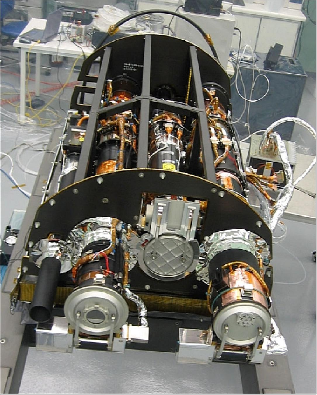
Legend of Figure 41: From left to right are the guide telescope, the COR1, the EUVI, and COR2 telescopes. HI1 and HI2 are mounted to the exterior of the observatory separately.
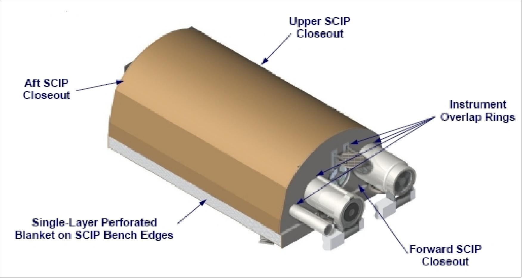
The SCIP (Solar Centered Imaging Package) contains three compact telescopes to view the solar disk and solar corona. The SCIP structure provides the required alignments, stiffness, and modularity to the three instruments. SCIP also contains the GT (Guide Telescope) that provides fine-pointing information to the S/C attitude control system and to FPS (Fine Pointing System) of the EUVI. The pointing strategy is based on pointing the S/C to minimize the scattered light in COR1 and relying upon the SCIP structure to assure that COR2 and EUVI are within acceptable pointing tolerances. The SCIP and the HI assemblies have their own camera electronics inside their enclosures. These units are known as CEB (Camera Electronics Box). The SCIP camera electronics are composed of three circuit cards with a common backplane interface. The CCD (Charge Coupled Device) camera electronics are designed for independent control of all instrument (COR1, COR2, HI, and EUVI) CCDs, a camera readout rate of 1 Mpixel/s through either of two CCD output ports, and 14-bit data quantization.
EUVI (Extreme Ultraviolet Imager). EUVI observes the chromosphere and innermost corona underlying the same portions of the corona and the heliosphere observed by COR1, COR2, and HI. Four EUV emission lines between 17.1 and 30.4 nm are observed. The EUVI design uses a small Ritchey-Chretien telescope of EIT (EUV Imaging Telescope) heritage on SOHO and of TRACE (Transition Region and Coronal Explorer) mission heritage. The improved mirror coatings, detector array, and telemetry allocation provide a higher sensitivity and image cadence of the EUVI instrument than previously possible. The optical system of EUVI, consisting of entrance filter, shutter, filter wheel, primary mirror and active secondary mirror, and a CCD array, provides pixel-limited imaging throughout the FOV in a compact envelope. The EUVI optics are fully baffled. The CCD detector assembly uses a backside-illuminated, backside-thinned and pacified array of size 2k x 2k with an EUV quantum efficiency >70%. The detector is passively cooled by a radiator. EUVI has its own ISS to satisfy its jitter requirements. The ISS includes the EUVI secondary mirror as the actuator and GT as the high-accuracy angular motion sensor. The EUVI secondary mirror is actuated to compensate for the S/C jitter. The GT is used to provide fine-pointing angular measurements to orient the boresights of the SECCHI telescopes to point toward the geometric center of the sun. The circular full sun FOV is ±1.7 Rsun. 76)
COR1 (Coronagraph1 Imager). The objective is to explore the inner corona in white light and pB down to 1.25 Rsun. COR1 observes the inner (1.4 - 4 Rsun) corona with a high frequency and polarization precision. The COR1 optical design is an all-refractive 7-element system. The instrument FOV is is 1.25-4 Rsun for a full field width of 2.13º and an aperture diameter of 36 mm. The spectral range is 650-750 nm. Images are collected at three different linear polarization angles. The occulter is attached to the second optical element in COR1, a doublet field lens. The final stage consists of two doublets, along with the filter and polarization optics. The stage takes the chromatically aberrated image of the corona, near the occulter, and relays it onto the CCD detector. The 2k x 2k detector data is summed on-board to 1k x 1k images to produce 7.5 arcsec pixels.
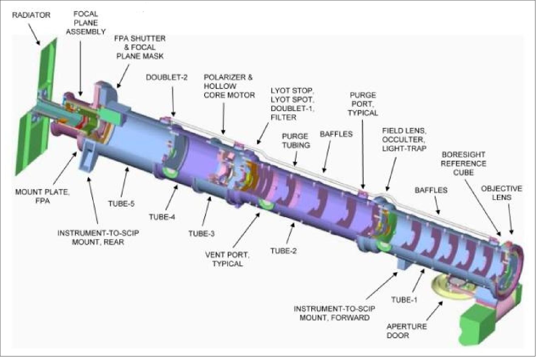
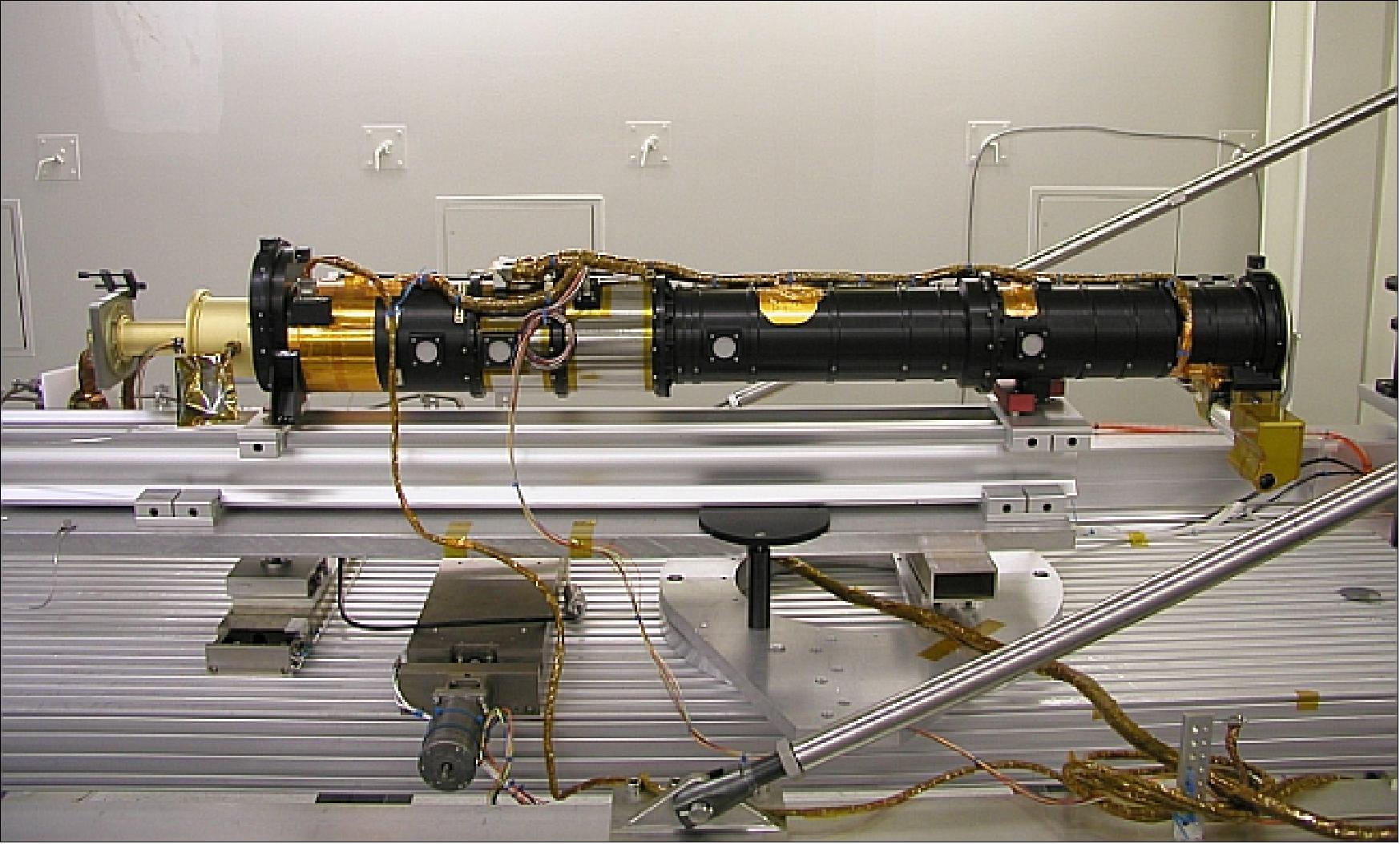
COR2 (Coronagraph2 Imager). The objective is to explore the outer corona (2-15 Rsun) in white light and pB with high spatial and temporal resolutions. The COR2 design is of LASCO heritage on SOHO. The optical design of the instrument uses a classical externally occulted Lyot design with an entrance aperture diameter of 30.5 mm and an overall length of 1348 mm. The spectral range and polarization technique is the same as COR1 to provide a seamless transition between the two regions.
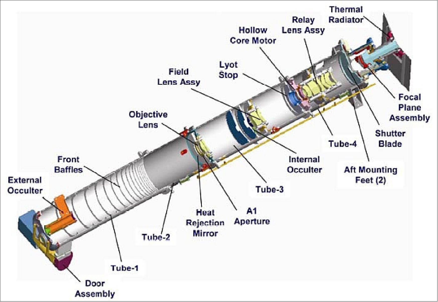
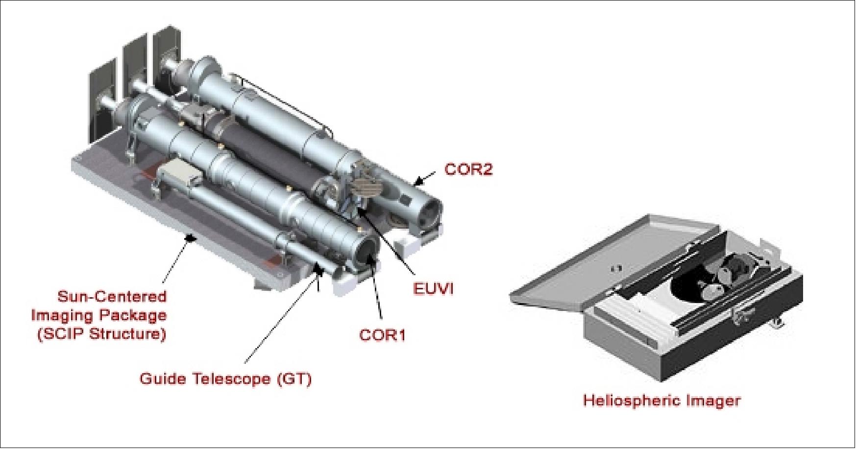
HI (Heliospheric Imager). The instrument assembly is being developed by a UK-led team involving the University of Birmingham and the Rutherford Appleton Laboratory (RAL), in collaboration with Centre Spatial de Liege (CSL), Belgium, and the Naval Research Laboratory (NRL), USA. The PI is Richard Harrison. The objective is to extend the concept of traditional externally occulted coronagraphs to a new regime, by observing the heliosphere from the sun to the Earth (12-215 Rsun). 77) 78) 79)
The HI is a wide-angle visible-light imaging system for the detection of coronal mass ejection (CME) events in interplanetary space and, in particular, of events directed towards the Earth.
The HI assembly consists of two instruments, HI-1 and HI-2, the exterior baffle systems, the hinged baffle cover, the focal plane packages, the HI camera electronics, and the radiators for the CCDs. - HI-1 looks at the inner heliosphere to within 3.28º of the sun with an opening angle of 20º. The HI-1 camera uses a five-vane forward linear baffle system and a matching linear internal occulter, a 20º full field angle lens, and a 2048 x 2048 pixel format CCD.
The HI-2 camera looks further out, from an elongation of 18.36º, with an opening angle of 70º. The HI-2 objective is set deep within the forward baffle system shadow at a diffraction angle of 16.5º. The HI-2 camera consists of a wide-angle fisheye lens and a CCD detector array.
Parameter | HI-1 | HI-2 |
FOV (Field of View) |
|
|
CCD format | 2048 x 2048 x 13.5 | 2048 x 2048 x 13.5 |
Plate scale | 35.15”/pixel | 2.05’/pixel |
Objective | AR coated | AR coated |
Passband | 6500 - 7500 | 4000 - 10000 |
Instrument background | < 3 x 10-13 B/B0 | < 5 x 10-15 B/B0 |
Nominal exposure time | 12 s | 60 s |
SNR | ≥ 30/(pixel hr)1/2 | ≥ 15.5 /(pixel hr)1/2 |
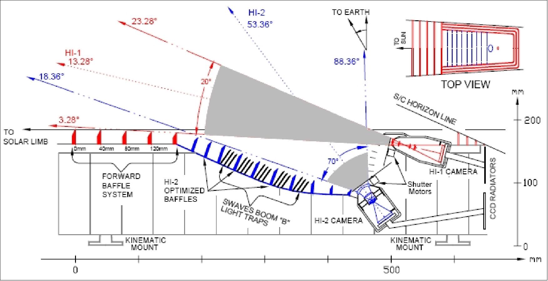
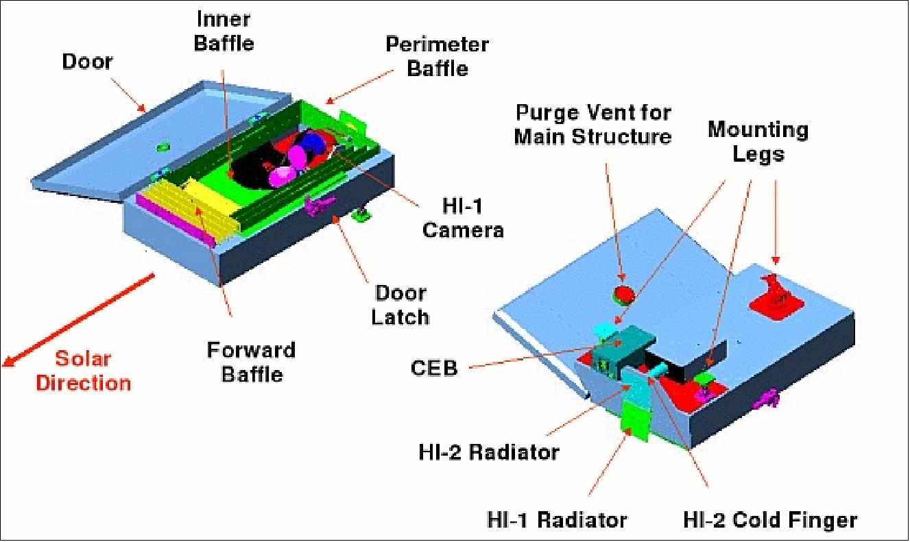
The SEB (SECCHI Electronics Box) provides all command and data handling functions and is the only electronic interface with the S/C. SEB consists of a control computer, interfaces for the camera and CCD, fine-pointing and jitter control electronics, a housekeeping and data acquisition system, and power conversion. A RISC-based single board computer RAD6000 (32 MHz) is used. The image processing and compression software employs such compression routines as Rice (lossless) and a lossy wavelet compression (H-compress) technique.
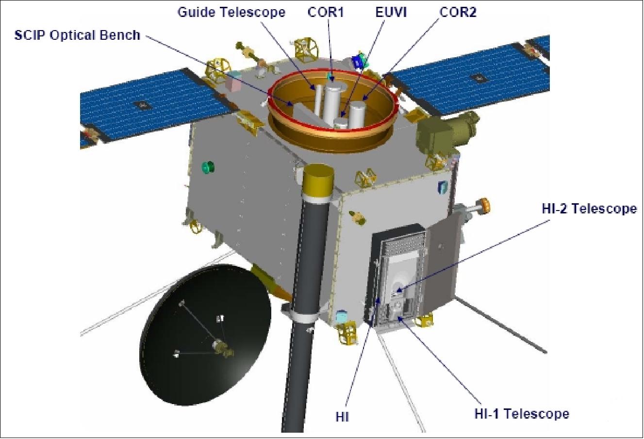
IMPACT (In-situ Measurements of Particles and CME Transients)
IMPACT (In-situ Measurements of Particles and CME Transients), PI: Janet G. Luhmann of the Space Sciences Laboratory of UCB (University of California at Berkeley). The IMPACT investigation science focuses on the magnetic connections to the sun and topology of interplanetary CME-related interplanetary disturbances, and the energetic particles that precede and accompany these disturbances as they move toward Earth. IMPACT addresses these with a combination of solar wind electron and solar energetic particle instrumentation that, with the PLASTIC solar wind ion measurements provide the comprehensive, identical in-situ measurements at the two STEREO spacecraft locations necessary to relate what is seen in the SECCHI images to the space weather environment at 1 AU.
IMPACT's solar wind electron instruments (SWEA, STE) and magnetometer (MAG) are mounted on the STEREO boom, while the SEP (Solar Energetic Particles) instruments are on the spacecraft body. All of these instruments use the IDPU (IMPACT Instrument Data Processing Unit), which serves as a single interface to the spacecraft. The PLASTIC solar wind ion instrument also uses the IMPACT IDPU. IMPACT's boom instruments consist of the electron instruments SWEA (Solar Wind Electron Analyzer) and STE (Suprathermal Electron Telescope) and the magnetometer. The SEP package is also a multi-instrument (4) system, but it is more physically integrated, and so included under one heading here.
SWEA (Solar Wind Electron Analyzer). The objective is designed to measure the distribution function of the solar wind core and halo electrons from about 1 eV to several keV, with high spectral and angular resolution over practically the full spherical range. This capability allows the distinction between these components in detail during both undisturbed periods and the passage of CME generated disturbances, when the interplanetary field rotates far out of the ecliptic plane.
SWEA consists of a hemispherical top hat ESA (ElectroStatic Analyzer) that provides a 360º FOV in a plane, combined with electrostatic deflectors to provide nearly 4 pi coverage when SWEA is mounted at the end of the STEREO boom. The inner plate radius is 3.75 cm and the plate separation is 0.28 cm. The resulting energy resolution dE/E is 18%, and the geometric factor is 0.01 cm2 sr E (eV). SWEA compensates for the effects of spacecraft potential on the lowest energy particles by having an outer hemisphere that can be biased according to the plasma density measured by the PLASTIC solar wind ion instrument.
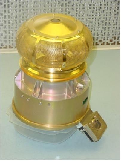
STE (Suprathermal Electron Telescope). STE is a new instrument that covers electrons in the energy range of about 2-20 keV with approximately 50 times the sensitivity of previous instruments. These higher energy electrons are frequently accelerated in flares or impulsive flare-like bursts, and they produce solar type III radio bursts as they escape the sun. They provide a unique tracer of the footpoints of CME and normal interplanetary magnetic fields, and allow the measurement of the length of those field lines. In addition, an electron superhalo is continuously present in the interplanetary medium at those energies. STE utilizes passively cooled SSDs (Silicon Semiconductor Devices) that measure all energies simultaneously. The STE consists of two detector arrays of four SSDs in a row, each about 0.1 cm2 in area and about 500 μm thick. Each array looks through a rectangular opening that provides a FOV of about 20º x 80º for each SSD with the 80º direction perpendicular to the ecliptic. Adjacent FOVs are offset for a total FOV of about 80º x 80º. The two arrays are mounted back-to-back, looking in opposite directions, centered about 25º from the average Parker Spiral field direction. STE is located just inboard of SWEA on the STEREO boom to clear its FOV and remain in shadow.
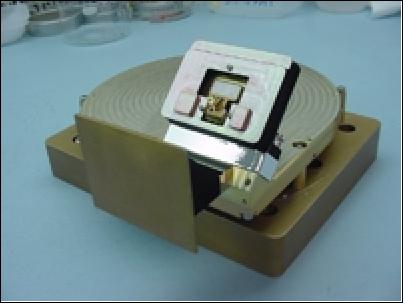
MAG (Magnetometer). The MAG system is a simplified version of the magnetometers flown on Mars Global Surveyor and Lunar Prospector. It is a triaxial fluxgate design, mounted on the STEREO boom (about 4m) just inboard of the SWEA and STE instruments. The fluxgate sensors use a ring core geometry, with magnetic cores consisting of permalloy. The units are compact, low power, and ultra-stable. To optimize sensitivity at the low field values to be found in interplanetary space, the magnetometer dynamic range is divided into 8 ranges that are automatically switched whenever the field being measured exceeds or falls below predetermined levels. The maximum range is sufficiently large to allow IMPACT MAG magnetic field measurements in the Earth's magnetic field during the commissioning phase orbits.
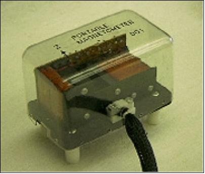
SEP (Solar Energetic Particles) package. SEP consists of 4 separate instruments that cover the full solar energetic particle energy, flux and composition ranges needed to meet the STEREO science goals. The SEP instruments include the SEPT (Solar Electron Proton Telescope), SIT (Suprathermal Ion Telescope), LET (Low Energy Telescope), and the HET (High Energy Telescope). Together, the SEP instruments measure electrons, protons and heavier ions from several tens of keV to approximately 100 MeV (or MeV/nucleon).
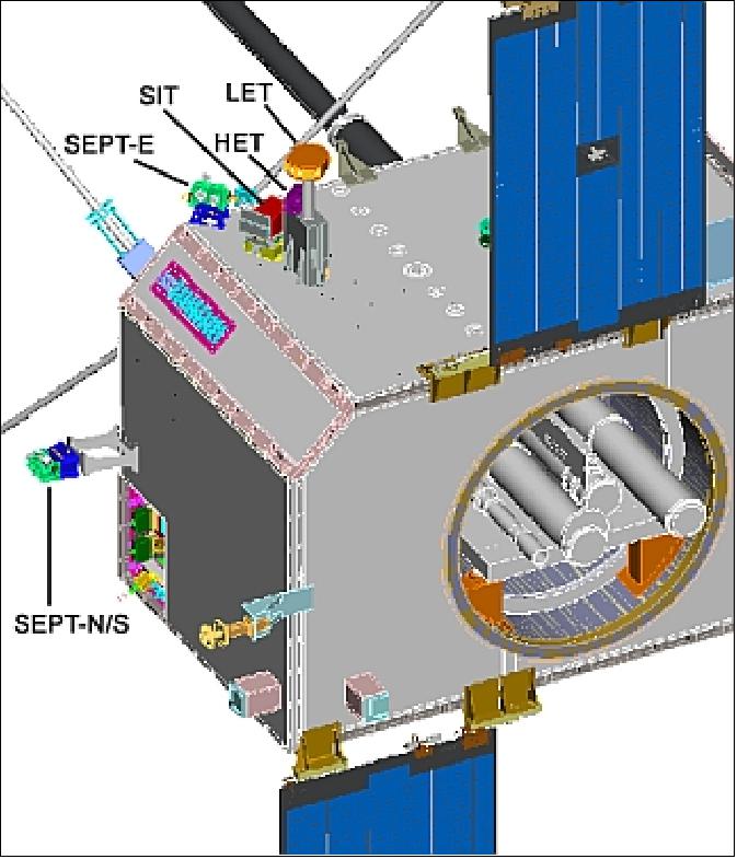
• SEPT (Solar Electron Proton Telescope). SEPT consists of two dual, double-ended magnet/foil solid state detector particle telescopes that cleanly separate and measure electrons in the energy range 20-400 keV and protons from 20-7000 keV, while providing anisotropy information through the use of several FOVs. Each SSD detector in SEPT is 300 μm thick and 0.53 cm2 in area. A rare-earth permanent magnet is used to sweep away electrons for ion detection, while a parylene foil transmits electrons but stops protons. SEPT is divided into two pieces for FOV reasons. The SEPT-E telescope is housed with the rest of the SEP package, located on the body of the S/C. It looks in the ecliptic plane along the Parker Spiral magnetic field direction, both forward and backward. SEPT-N/S is housed separately at a different spacecraft location and looks out of the ecliptic plane perpendicular to the nominal magnetic field, both north and south. The viewing cones for the SEPT telescopes are each about 60º.
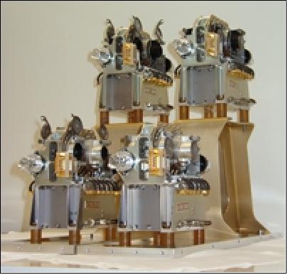
• SIT (Suprathermal Ion Telescope) of GSFC, MPI and University of Maryland. SIT is a time-of-flight ion mass spectrometer that measures elemental composition of He-Fe ions over the energy range of about 30 keV/nucleon to 2 MeV/nucleon. The FOV angles are 17º x 44º, with the 44º angle in the ecliptic plane, centered approximately 60º from the spacecraft-sun line to avoid sunlight while still intercepting significant numbers of Parker Spiral field controlled energetic ion fluxes. The telescope analyzes ions that enter through thin entrance foils and stop in a solid state detector. A time-of-flight approach for determining the composition utilizes start and stop times obtained from secondary electrons entering a MCP (MicroChannel Plate) detector system. The MCP and SSD areas are each 6.0 cm2. The SIT geometric factor allows study of even small SEP events.
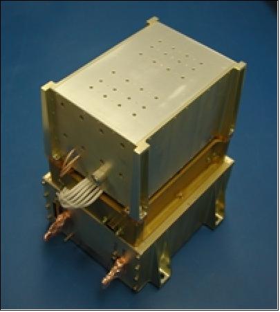
• LET (Low Energy Telescope) of Caltech, GSFC and JPL. LET is a special double-fan arrangement of 14 solid-state detectors designed to measure protons and helium ions from about 1.5 to 13 MeV/nucleon, and heavier ions from about 2 to 30 MeV/nucleon. LET uses a standard dE/dx vs. E-technique, identifying particles that stop at depths of about 20-70 μm and about 70-2000 μm corresponding to two general energy ranges. The large FOV spans from 20º above to 20º below the ecliptic plane and extends 65º to either side of the forward and backward Parker Spiral field directions in the ecliptic plane. Like SIT, LET's large geometric factor also ensures the detection of even small SEP events.
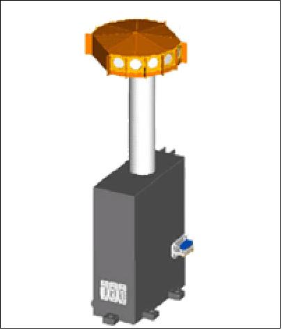
• HET (High Energy Telescope). HET also uses the solid-state detector, dE/dx vs. E-approach, but in a six-detector, more traditional linear arrangement designed to measure protons and helium ions to 100 MeV/nucleon and energetic electrons to 5 MeV. HET identifies particles that stop at depths of 1 to 8 μm in the detectors. Some information will also be obtained on heavier nuclei up through Fe using the dE/dx vs. E signatures and ranges together, and penetrating particles will be analyzed. The FOV covers a 47.5º cone around the Parker Spiral field direction. SIT, LET and HET are all packaged together with the SEPT-E subsystem and a SEP CPU (Central Processing Unit) in the main SEP package on the spacecraft body, but they use the IMPACT IDPU to interface with the spacecraft together with the rest of IMPACT.
PLASTIC (PLAsma and SupraThermal Ion and Composition)
PLASTIC instrument, PI: Antoinette Galvin of UNH (University of New Hampshire), collaboration of UNH, University of Bern, Switzerland, MPE Garching and University of Kiel, Germany, and NASA/GSFC. The objective of PLASTIC is to study coronal SW (Solar Wind) and solar wind-heliospheric processes. The science objective is to measure ions in the energy-per-charge range of 0.3 to 100 keV/e. The instrument performs three functions in one package: 80) 81)
• Measurement of the distribution functions of solar wind protons and alpha particles (providing density, velocity, kinetic temperature and its anisotropy), with a time resolution of about one minute.
• The SW sector also provides, on at least five minute resolution, the elemental composition, charge state distribution, kinetic temperature, and velocity of the more abundant solar wind heavy ions (e.g., C, O, Ne, Mg, Si, and Fe).
• The PLASTIC Wide Angle Partition measures the distribution functions of suprathermal ions H through Fe, with a comparatively large geometrical factor that allows the study of suprathermal particles, including shock-accelerated particles and pick up ions. Together with IMPACT measurements, PLASTIC completes the required STEREO mission in-situ observations.
The PLASTIC instrument design is based on the CIS/CODIF (Cluster Ion Spectrometer/Composition and Distribution Functions) sensor onboard the Cluster mission (with a much improved mass resolution to resolve individual ionic charge states of heavy ions in the solar wind); PLASTIC includes an electrostatic deflection analyzer, a time-of-flight section, and solid-state detectors (SSD's) for energy measurement. The instrument provides a large IFOV (resolved in-ecliptic and in polar angles) with measurements taken at high time resolution (1-5 minutes) spanning an ion energy range of 0.3-100 keV/e. To handle a large range of particle fluxes, the entrance system of PLASTIC employs collection apertures with different geometric factors for the bulk solar wind (H ~96%, He ~4%) and for the heavier, less-abundant ions (<1%) and suprathermals.
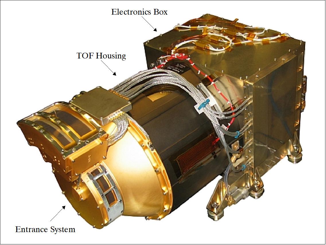
SWAVES (STEREO/WAVES)
SWAVES is an interplanetary radio burst tracker device. PI: Jean-Louis H. Bougeret of CNRS (Centre National de la Recherche Scientifique) Observatory of Paris, with instrument management by the University of Minnesota. The goal of the SWAVES radio and plasma waves investigation is to obtain unique and critical observations for all primary science objectives of the STEREO mission, the generation of CMEs, their evolution and their interaction with Earth's magnetosphere. SWAVES can probe a CME from lift-off to Earth by detecting the coronal and interplanetary (IP) shock of the most powerful CMEs, providing a radial profile through spectral imaging, determining the radial velocity from about 2 Rsun (from center of sun) to Earth, measuring the density of the volume of the heliosphere between the sun and Earth, and measuring important in situ properties of the IP shock, magnetic cloud, and density compression in the fast solar wind stream that follows. 82) 83)
SWAVES achieves these goals by measuring IP (Interplanetary) type II and type III radio bursts, both remotely and in-situ (the type II radio bursts are signatures of the propagation of CMEs, while type III radio bursts represent the propagation of energetic electrons associated with flares).
• SWAVES antenna system (see Figure 11 and 58). SWAVES uses three mutually orthogonal monopole stacer antenna elements as its prime sensors (built by the University of California, Berkeley), each 6 meters in length. The three monopoles are deployed away from the sun so that they remain out of the fields of view of sunward looking instruments. The antenna design optimizes the radio burst tracking in the 16MHz - 30kHz range and maintains a high SNR for expected solar type II, type III and other solar and IP radio emissions.
• Preamplifiers. A high input impedance preamplifier is connected to each of the three electric monopoles.
• Radio receivers. There are five radio receivers in the SWAVES instrument to cover the following frequency ranges: 1) LFR Lo: 10-40 kHz; 2) LFR Hi: 40-160 kHz; 3) HFR: 0.125-16 MHz; 4) FFR1: 32 MHz fixed frequency; 5) TDS: 250,000 samples/s time series snapshots.
• Housekeeping and low-rate science. This system provides digitized and selectable housekeeping data to monitor the status and health of the various parts of the instrument.
• Calibration. The instrument contains its own internal calibration circuitry. An internal calibration sequence will be invoked about once per day.
The focal point of SWAVES instrument commanding and operations will be performed at the UMN (University of Minnesota).
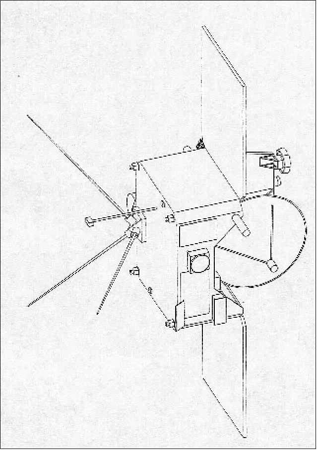
Space weather data: “Real-time” in situ space weather data products from IMPACT and PLASTIC, consisting of approximately 1 minute cadence information on solar wind electrons and ions, solar energetic particles and magnetic fields are packaged in the data stream from the IMPACT IDPU with the regular coded science and housekeeping telemetry from the instruments. The bulk of the space weather data is expected to come from SECCHI, producing about 7 images/hour (256 x 256 pixels). In addition, SWAVES is producing a 1 minute averaged dynamic spectrum.
STEREO Mission Technology Summary
• Stereoscopic image processing
• Light-weight coronagraphs
• High sensitivity, low-scatter, wide angle photometry
• CME radio tracker
• Autonomous operation - beacon mode.
Ground Segment
The STEREO ground system was developed with the intention that the two spacecraft could be operated simultaneously and independently of each other. To achieve this goal, the ground system architecture is such that for most MOC (Mission Operations Center) functions, there are separate hardware/software components for each spacecraft. This approach minimizes the risk of confusion among operators and other personnel, and it allows for the simultaneous operation of both spacecraft. 84)
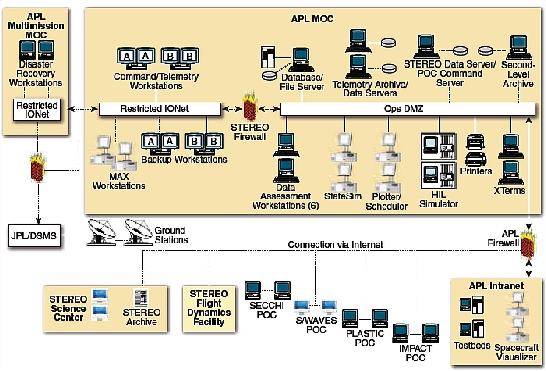
The STEREO mission operations were designed around the data return requirement of an average of 5 Gbit/day of data, and although loss of some data was deemed acceptable, maximizing data return was kept a priority. After 6 months in heliocentric orbit, STEREO returned a daily average of 7.0 Gbit of data from the Ahead spacecraft and 7.7 Gbit of data from the Behind spacecraft.
STEREO employs decoupled spacecraft bus/instrument operations modeled after the TIMED (Thermosphere, Ionosphere, Mesosphere Energetics and Dynamics) program. Operating only the spacecraft bus and engaging a highly automated system, STEREO mission operations are able to use a small team to safely operate two spacecraft simultaneously. The STEREO ground system was developed to support this concept of highly automated operations from the APL MOC (Mission Operations Center) and multiple POCs (Payload Operations Centers). In addition, the STEREO ground system includes a SDS (STEREO Data Server) for the distribution of all of the data and products required for operation of the STEREO observatories, as well as two HIL (Hardware-In-the-Loop) simulators for verification of commanding and analysis of anomalies.
The STEREO ground system is segmented into several distinct network “zones.” This design ensures the integrity of the STEREO spacecraft as well as STEREO and APL network resources. All real-time command and control of the STEREO spacecraft originates in the STEREO ground system Restricted IONet (Internet Protocol Operational Network). The Restricted IONet is a secure NASA network that places secure controls on the users and facilities. Each spacecraft has a primary and a backup command workstation in the Restricted IONet. Dedicated Memory Allocation Examiner (or “MAX”) workstations for each spacecraft are also located on this network. Additionally, each spacecraft has a third command workstation, one that is remotely located in a separate building on the APL campus. These workstations would be used to ensure spacecraft health and safety in the event that the entire STEREO MOC becomes inaccessible.
The STEREO firewall isolates the Restricted IONet from the remaining components of the STEREO MOC ground system, which reside in the operations “demilitarized zone” (Ops DMZ) network (which has fewer restrictions and is a less secure network). There are 6 workstations assigned in the Ops DMZ, 3 per spacecraft, telemetry archive servers with 10 TB RAID (Redundant Array of Independent Disk) storage arrays (one system for each spacecraft), a second-level archive server, an SDS, and a database server. Additionally, each spacecraft has a dedicated HIL simulator with its own command and telemetry workstation.
An APL firewall isolates the Ops DMZ from the APL intranet. The STEREO development community functions in this network zone. Software development workstations and testbeds/mini-MOCs are connected to the APL intranet. This configuration allows the developers and testers to access their systems from other laboratory resources, such as employee desktop computers and laptops.
A separate dedicated network, known as the Science DMZ, supports instrument POCs located at APL. In addition to the APL-located instrument POCs, each instrument has primary POCs located at their home institutions, which also have access to the STEREO instrument command and telemetry servers, as well as the SDS, via an Internet connection. The SSC (STEREO Science Center) and the FDF (Flight Dynamics Facility), both located at GSFC (Goddard Space Flight Center) in Greenbelt, Maryland, also communicate with the STEREO MOC via the Internet by using FTP (File Transfer Protocol).
SDS (STEREO Data Server): The STEREO ground system consists of the APL STEREO MOC, the DSMS (Deep Space Mission System) ground stations, the instrument POCs, the FDF, and the SSC. To coordinate mission operations between these teams and return the science data to the mission scientists, a routine flow of data products is necessary. Most of these data products are available to the STEREO community through the SDS. The SDS consists of a webpage in the APL MOC where data products can be transferred to the community via FTP.
STEREO Mission Operations
The APL STEREO MOT (Mission Operations Team) works in the MOC and has the primary responsibility of management of the spacecraft bus, including the development of command messages and the uplink to the spacecraft by way of the DSMS. Recovery of spacecraft bus engineering (state-of-health) telemetry and the performance analysis based on this telemetry are also performed at the MOC. The MOC receives instrument command messages from the POCs and, after verification that the command APIDs (Application Identifiers) are appropriate for the POC they came from, queues these for uplink to the spacecraft on the basis of start and expiration times appended to the command messages by the POC. The MOC does not directly verify any instrument commands and does not decommutate or analyze any instrument telemetry aside from currents and temperatures observed from the spacecraft side of the instruments. Each POC is individually responsible for the health and safety of its instrument. In addition to the POCs, the other external teams that support STEREO mission operations are the DSN (Deep Space Network); the FDF, which performs navigation for the STEREO mission; and the SSC, which is the primary archive of STEREO data and the focal point for education and public outreach.
External operations facilities:
• POCs: The POCs are the instrument operations centers that generate the commands for each of the four STEREO instrument suites (SECCHI, IMPACT, SWAVES, and PLASTIC) and monitor instrument health and safety. These centers are located at the Navel Research Laboratory in Washington, DC (SECCHI); the University of California, Berkeley (IMPACT), the University of Minnesota, Minneapolis (SWAVES); and the University of New Hampshire, Durham (PLASTIC). These are the home bases for the instrument POCs, but they are able to operate remotely when necessary, and they also maintain a presence at the MOC.
• DSN: The DSN is being used to provide communications to both spacecraft from launch to end of life. The use of all three DSN antenna facilities—Goldstone, Madrid, and Canberra—is required to determine the elevation component for the navigation of each spacecraft. Nominally, a 3.5-5 hour track, depending on spacecraft range, centered every 24 h per spacecraft will be conducted by using the 34 m beam wave guide subnet.
The MOC is connected to the DSN via Restricted IONet links. Commands will be flowed to the DSN by using the standard Space Link Extension Service over the Restricted IONet, and real-time telemetry will be flowed from the DSN to the MOC over the Restricted IONet by using legacy the UDP (User Datagram Protocol) service. Playback data received at the DSN station will be flowed to the Central Data Recorder at the JPL (Jet Propulsion Laboratory), where they will in turn be flowed in half-hour increments to the MOC via FTP as intermediate data recorder (IDR) files. Orbit data for each spacecraft will be provided to the DSN from the FDF for acquisition, and ranging data will be distributed from the DSN to the FDF for orbit determination purposes over the Restricted IONet.
• FDF (Flight Dynamics Facility): The FDF at the NASA GSFC determines the orbits of the observatory from tracking data provided by the DSN ground stations, and it generates predicted DSN station contact periods and predicted and definitive orbit data products. The FDF also generates orbital ephemeris data in support of orbit maneuvers that satisfy science and mission requirements, and it transfers this information to the STEREO MOC via the FDF Products Center.
• SSC (STEREO Science Center): The SSC is located at the NASA GSFC and serves four main functions for the STEREO mission. First, it is the prime archive of STEREO telemetry and data, and it serves that data to the international science community, and to the general public, through its own website. It is also the collection site, processing center, and distribution point for STEREO space weather beacon data. Science coordination between the STEREO instruments, and between STEREO and other observatories, is performed through the SSC. Finally, the SSC is the focal point for education and public outreach activities.
The STEREO observatories continually point at the Sun as they move away from the Earth at a rate of 22º/year while remaining approximately the same distance from the Sun throughout the mission. In this orbit, the solar array input power is sufficient to cover any instrument/spacecraft mode, and the observatory remains thermally stable. Each instrument has its own partitions to use on the SSR, which are typically set by the MOT to an overwrite mode. Thus, the instruments are left with no power, thermal, or SSR constraints other than managing the amount of data being placed in their SSR partitions that is ideal for the decoupled spacecraft/instrument operations concept employed by STEREO. This operations concept greatly simplifies mission operations and allows for a smaller operations team size and automated, unattended real-time operations for most of the spacecraft contacts.
Summary: The STEREO ground system is uniquely divided between the two spacecraft, allowing simultaneous communications with the two spacecraft while minimizing the risk of confusion. The mission operations tools used for planning, real-time operations, and assessment of spacecraft performance allow for the safe operation of two spacecraft simultaneously. Specifically, separation of command and memory management between the two spacecraft is rigorously maintained. STEREO mission operations are being accomplished with a minimal number of staff while the science data return is kept well above the minimum requirement for mission success.
References
1) G. L. Baer, J. E. Eichstedt, D. A. Ossing, “Solar Terrestrial Relations Observatory (STEREO) Mission and Concept of Operations,” Proceedings of the 13th AIAA/USU Conference on Small Satellites, Aug. 23-26, 1999, Logan UT, SSC99-IIb-1
2) “The Sun and Heliosphere in Three Dimensions,” Report of the NASA Science Definition Team for the STEREO Mission
3) J. Galloway, “STEREO Mission Design,” NASA/GSFC paper, Sept. 1, 1999
5) http://www.nasa.gov/mission_pages/stereo/main/index.html
6) http://stereo.gsfc.nasa.gov/
7) “STEREO—The Solar Terrestrial Relations Observatory,” Johns Hopkins APL Technical Digest, Vol. 28, No. 2, 2009, URL: http://www.jhuapl.edu/techdigest/TD/td2802/index.htm
8) Michael L. Kaiser, “STEREO: Science and Mission Overview,” Johns Hopkins APL Technical Digest, Vol. 28, No. 2, 2009, pp. 94-103, URL: http://www.jhuapl.edu/techdigest/TD/td2802/Kaiser.pdf
9) K. Strohbehn, M. N. Martin, S. E. Jaskulek, “Micro Digital Solar Attitude Detector,” JHU/APL Technical Digest, Vol. 22, No 2, 2001, pp. 104-105
10) J. R. Tanzman, “Material Considerations in the STEREO Solar Array Design,” Proceedings of the 57th IAC/IAF/IAA (International Astronautical Congress), Valencia, Spain, Oct. 2-6, 2006, IAC-06-C2.P.1.07
11) T. M. Betenbaugh, “Structural Flight Qualification of the Solar TErrestrial RElations Observatory,” Proceedings of the 57th IAC/IAF/IAA (International Astronautical Congress), Valencia, Spain, Oct. 2-6, 2006, IAC-06-C2.1.02
12) M. L. Kaiser, W. J. Adams, “STEREO Mission Overview,” Proceedings of the 2007 IEEE Aerospace Conference, Big Sky, MT, March 3-10, 2007
13) http://stereo.jhuapl.edu/press/pdfs/factsheet.pdf
14) Stuart W. Hill, Teresa M. Betenbaugh, Weilun Cheng, “STEREO Spacecraft Mechanical Design, Integration, and Testing,” Johns Hopkins APL Technical Digest, Vol. 28, No. 2, 2009, pp. 187-197, URL: http://www.jhuapl.edu/techdigest/TD/td2802/Hill.pdf
15) John W. Hunt Jr., J. Courtney Ray, “STEREO Guidance and Control System On-Orbit Pointing Performance,” Johns Hopkins APL Technical Digest, Vol. 28, No. 2, 2009, pp. 145-154, URL:http://www.jhuapl.edu/techdigest/TD/td2802/Hunt.pdf
16) M. L. Kaiser, “The STEREO Mission: A New Approach to Space Weather,” Proceedings of 85th AMS (American Meteorological Society) Annual Meeting,, San Diego, CA, Jan. 9-13, 2005
17) “STEREO Science Operations Plan,” Dec. 10, 2004, http://stereo-ssc.nascom.nasa.gov
/publications/stereo_sop.pdf
18) David W. Dunham, José J. Guzmán, Peter J. Sharer, “STEREO Trajectory and Maneuver Design,” Johns Hopkins APL Technical Digest, Vol. 28, No. 2, 2009, pp. 104-125, URL: http://www.jhuapl.edu/techdigest/TD/td2802/Dunham.pdf
19) ”Solar Eruption Arrives at Earth,” NASA Solar Cycle 25, 13 October 2021, URL: https://blogs.nasa.gov/solarcycle25/2021/10/13/solar-eruption-arrives-at-earth/
20) Miles Hatfield, ”Mars-Directed CME Erupts from the Sun,” NASA, 22 April 2021, URL: https://www.nasa.gov/image-feature/mars-directed-cme-erupts-from-the-sun
21) Miles Hatfield, ”STEREO Watches Comet ATLAS as Solar Orbiter Crosses Its Tail,” NASA Feature, 5 June 2020, URL: https://www.nasa.gov/image-feature/goddard/
2020/stereo-watches-comet-atlas-as-solar-orbiter-crosses-its-tail
22) https://stereo-ssc.nascom.nasa.gov/where.shtml
23) https://stereo.gsfc.nasa.gov/where.shtml
24) ”STEREO-B Status Update,” NASA, 4 January 2019, URL: https://stereo-ssc.nascom.nasa.gov
/behind_status.shtml
25) Lina Tran, Rob Garner, ”New Insights on Comet Tails Are Blowing in the Solar Wind,” NASA, 2 November 2018, URL: https://www.nasa.gov/feature/goddard/
2018/new-insights-on-comet-tails-are-blowing-in-the-solar-wind
26) Oliver Price, Geraint H. Jones, Jeff Morrillc,Mathew Owens, Karl Battams, Huw Morgan, Miloslav Drückmuller, Sebastian Deiries, ”Fine-scale structure in cometary dust tails I: Analysis of striae in Comet C/2006 P1 (McNaught) through temporal mapping,” Science Direct, Icarus, Volume 319, February 2019, Pages 540-557, URL: https://tinyurl.com/y8dauz99
27) ”SwRI-led team creates high-fidelity images of Sun’s atmosphere,” SwRI, 18 July 2018, URL: https://www.swri.org/press-release/high-fidelity-images-sun-atmosphere?
utm_source=EurekAlert&utm_medium=Distribution&utm_campaign=HiFi-PR
28) C. E. DeForest , R. A. Howard , M. Velli , N. Viall , and A. Vourlidas, ”The Highly Structured Outer Solar Corona,” The Astrophysical Journal, Vol. 862, 20 July 2018, https://doi.org/10.3847/1538-4357/aac8e3, URL: http://iopscience.iop.org/article/10.3847/1538-4357/aac8e3/pdf
29) https://stereo.gsfc.nasa.gov/where.shtml
30) ”Magnetic coil springs accelerate particles on the Sun,” MPS (Max Planck Institute for Solar System Research) Press Release, 10 Jan. 2018, URL: http://www.mps.mpg.de
/Magnetic-coil-springs-accelerate-particles-on-the-Sun
31) R. Bucík, D. E. Innes, L. Guo, G. M. Mason, M. E. Wiedenbeck, ”Observations of EUV waves in He-rich solar energetic particle events,” The Astrophysical Journal, Volume 812, Number 1, Published October 10, 2015, doi:10.1088/0004-637X/812/1/53, URL: http://iopscience.iop.org
/article/10.1088/0004-637X/812/1/53/pdf
32) Lisa Grossman, ”The sun’s outer atmosphere is far more complex than previously thought,” Science News, 19 Dec. 2017, URL: https://www.sciencenews.org/article/sun-corona-outer-atmosphere-complex
33) Laura Snider, ”Planetary waves, first found on Earth, are discovered on Sun,” NCAR, March 27, 2017, URL: https://www2.ucar.edu/atmosnews/news/126091
/planetary-waves-first-found-on-earth-are-discovered-on-sun
34) Scott W. McIntosh, William J. Cramer, Manuel Pichardo Marcano, Robert J. Leamon, ”The detection of Rossby-like waves on the Sun,” Nature Astronomy, Vol. 1, Article No: 0086 (2017), doi:10.1038/s41550-017-0086, Published online: 27 March 2017, URL:http://tinyurl.com/kys8e62
35) ”STEREO-B Status Update,” STEREO Science Center, Oct. 26, 2016, URL: https://stereo-ssc.nascom.nasa.gov/behind_status.shtml
36) Sarah Frazier, ”STEREO: 10 Years of Revolutionary Solar Views,” NASA, October 26, 2016, URL: https://www.nasa.gov/feature/goddard/2016/stereo-10-years-of-revolutionary-solar-views
37) ”Sun 360: STEREO Mission’s 10 Year Retrospective,” NASA, 2016, URL: https://stereo.gsfc.nasa.gov/10year/img/STEREOBooklet_11webA.pdf
38) Karen C. Fox, ”NASA Establishes Contact With STEREO Mission,” NASA, Aug. 22, 2016, URL: http://www.nasa.gov/feature/goddard/2016/nasa-establishes-contact-with-stereo-mission
39) ”SwRI-led study finds that a comet’s tail may shed light on solar wind heating,” SwRI, October 13, 2015, URL: http://www.swri.org/9what/releases/2015/swri-encke-comet-tail-solar-wind.htm#.Vh8l3isib3U
40) ”Comet Encke: A Solar Windsock Observed by NASA’s STEREO,” NASA, Oct. 13, 2015, URL: http://www.nasa.gov/feature/goddard/comet-encke-a-solar-windsock-observed-by-nasa-s-stereo
41) “NASA Cites the Return of the STEREO-A Spacecraft,” NASA, July 16, 2015, URL: http://www.nasa.gov/feature/goddard/stereo/return-of-the-stereo-a-spacecraft
42) “NASA Response to the 2015 Senior Review for Heliophysics Operating Missions,” NASA, July 10, 2015, URL: http://science.nasa.gov/media/medialibrary/2015/07/10/NASAResponse2015SeniorReview_FINAL.pdf
43) “The 2015 Senior Review of the Heliophysics Operating Missions, NASA, June 11, 2015, URL: http://science.nasa.gov/media/medialibrary/2015/07/10/HeliophysicsSeniorReview2015_FINAL.pdf
44) “Loss of Contact with STEREO Behind,” Stereo Science Center, Nov. 7, 2014, URL: http://stereo-ssc.nascom.nasa.gov/behind_status.shtml
45) Karen Fox, “STEREO Solar Conjunction,” NASA/GSFC, July 3, 2014, URL: http://svs.gsfc.nasa.gov
/cgi-bin/details.cgi?aid=11602
46) NASA, Jan. 06, 2014, URL: http://stereo.gsfc.nasa.gov/status.shtml
47) William Lotko, Doug Braun, Jim Drake, Joe Fennel, Richard R. Fisher, Joe Giacalone, Tim Horbury, Bob McCoy, Mark Moldwin, Alexei Pevtsov, John Plane, Howard Singer, Charles Swenson, “Senior Review 2013 of the Mission Operations and Data Analysis Program for the Heliophysics Extended Missions,” NASA, June 13, 2013, p. 47, URL: http://wind.nasa.gov/docs/Helio_SR_2013_FINAL_ALL.pdf
48) http://stereo-ssc.nascom.nasa.gov/where.shtml
49) Karen C. Fox, “NASA'S STEREO Shows Comet ISON Approaching the Sun,” NASA/GSFC, Nov. 26, 2013, URL: http://www.nasa.gov/content/goddard/
nasas-stereo-shows-comet-ison-approaching-the-sun/#.UuFH1PswdR4
50) Information provided by Joseph B. Gurman, STEREO Project Scientist, Solar Physics Laboratory, NASA/GSFC, Greenbelt, MD, USA.
51) “STEREO Reaches New Milestone At Its Sixth Anniversary,” NASA, Oct. 26, 2012, URL: http://www.nasa.gov/mission_pages/stereo/news/6th-anniversary.html
52) Karen C. Fox, “NASA STEREO Observes One of the Fastest CMEs On Record,” NASA/GSFC, August 13, 2012, URL: http://www.nasa.gov/mission_pages/stereo/news/fast-cme.html
53) Karen C. Fox, “NASA's STEREO Studies Extreme Space Weather,” NASA/GSFC, March 18, 2014, URL: http://www.nasa.gov/content/goddard/stereo-studies-extreme-space-weather/#.Uy73Oc52H5o
54) Robert Sanders, “Fierce solar magnetic storm barely missed Earth in 2012,” UCB News Center, March 18, 2014, URL: http://newscenter.berkeley.edu/2014/03/
18/fierce-solar-magnetic-storm-barely-missed-earth-in-2012/
55) Ying D. Liu, Janet G. Luhmann, Primož Kajdič, Emilia K.J. Kilpua, Noé Lugaz, Nariaki V. Nitta, Christian Möstl, Benoit Lavraud, Stuart D. Bale, Charles J. Farrugia, Antoinette B. Galvin, “Observations of an extreme storm in interplanetary space caused by successive coronal mass ejections,” Nature Communications, Vol. 5, No 3481, March 18, 2014, doi:10.1038/ncomms4481
56) Tony Phillips, “Near Miss: The Solar Superstorm of July 2012,” NASA Science News, July 23, 2014, URL: http://science.nasa.gov/science-news/science-at-nasa/2014/23jul_superstorm/
57) Trudy E. Bell, Tony Phillips, “A Super Solar Flare,” NASA, May 6, 2008, URL: http://science.nasa.gov/science-news/science-at-nasa/2008/06may_carringtonflare/
58) http://www.solarstorms.org/SRefStorms.html
59) Karen C. Fox, “STEREO Mission Celebrates Five Incredible Years of Science,” NASA, Oct. 25, 2011, URL: http://www.nasa.gov/mission_pages/stereo/news/five-years.html
60) “STEREO Sees Complete Far Side,” NASA, June 10, 2011, URL: http://www.nasa.gov/mission_pages/stereo/news/farside-060111.html
61) Tony Phillips, “First ever STEREO images of the entire sun,” NASA, Feb. 6, 2011, URL: http://science.nasa.gov/science-news/science-at-nasa/2011/06feb_fullsun/
62) Ken Kremer, “Earths Entire Star for the First Time on Super SUNday,” Universe Today, Feb. 6, 2011, URL: http://www.universetoday.com/83121/earths-entire-star-for-the-first-time-on-super-sunday/
63) “STEREO Captures Sun's Eruption,” NASA, Oct. 6, 2009, URL: http://www.nasa.gov/mission_pages/stereo/multimedia/filament_eruption.html
64) Tony Phillips, “Monster Waves on the Sun are Real,” NASA, Nov. 24, 2009, URL: http://science.nasa.gov/headlines/y2009/24nov_solartsunami.htm?list1291671
65) http://stereo.gsfc.nasa.gov/news/SolarTsunami.shtml
66) “Mystery of the Solar Tsunami—Solved,” NASA, Nov. 19, 2009, URL: http://www.nasa.gov/mission_pages/stereo/news/solar_tsunami.html
67) “NASA Sees the 'Dark Side' of the Sun,” Jan. 23, 2009, URL: http://science.nasa.gov/headlines/y2009/23jan_darkside.htm
68) Nancy Atkinson, “The Anatomy of a Solar Explosion in 3-D,” April 14, 2009, Universe Today, URL: http://www.universetoday.com/2009/04/14/the-anatomy-of-a-solar-explosion-in-3-d/
69) http://stereo.gsfc.nasa.gov/where.shtml
70) “NASA Spacecraft Make First 3-D Images of Sun,” April 24, 2007, URL: http://www.spacedaily.com/reports/NASA_Spacecraft_Make_First_3_D_Images_of_Sun_999.html
71) http://www.nrl.navy.mil/pressRelease.php?Y=2006&R=33-06r
72) R. A. Howard, J. D. Moses, D. G. Socker, “Sun Earth Connection Coronal and Heliospheric Investigation (SECCHI),” Proceedings of SPIE, Vol. 4139-26, 2000;
73) A. Vourlidas, “SECCHI Instrument Status Update,” STEREO/SECCHI Consortium Meeting, Brussels, Belgium, Apr. 14-15, 2003
74) R. A. Howard, “ SECCHI Sun Earth Connection Coronal and Heliospheric Investigation,” January 27, 2000, URL: http://stereo.nrl.navy.mil/orig_stereo/secchi_swg1.pdf
75) D. Moses, “SECCHI Instrument Suite System Description,” 2002, URL: http://www.sr.bham.ac.uk/instrument/02_SECCHI_Hardware.pdf
76) J.-P. Wuelser, J. R. Lemen, T. D. Tarbell, C. J. Wolfson, J. C. Cannon, B. A. Carpenter, D. W. Duncan, G. S. Gradwohl, S. B. Meyer, A. S. Moore, R. L. Navarro, J. D. Pearson, G. R. Rossi, L. A. Springer , R. A. Howard, J. D. Moses, J. S. Newmark, J.-P. Delaboudiniere, G. E. Artzner, F. Auchere, M. Bougnet, P. Bouyries, F. Bridou, J.-Y. Clotaire, G. Colas, F. Delmotte, A. Jerome, M. Lamare, R. Mercier, M. Mullot, M.-F. Ravet, X. Song, V. Bothmer, W. Deutsch, “EUVI: the STEREO-SECCHI extreme ultraviolet imager,” Proceedings of SPIE, 'Telescopes and Instrumentation for Solar Astrophysics,' Silvano Fineschi, Mark A. Gummin, Editors, Vol. 5171, Feb. 2004, pp. 111-122
77) J.-M. Defise, J.-P. Halain, E. Mazy, R. A. Howard, C. M. Korendyke, P. Rochus, G. M. Simnett, D. G. Socker, D. F. Webb, “Design of the Heliospheric Imager for the STEREO mission,” URL: http://www.promoptica.be/publications/stereo/hister.pdf
78) R. Harris, C. Davis, C. Eyles, “The STEREO Heliospheric Imager (HI): How to detect CMEs in the Heliosphere,” COSPAR 2004
79) R. A. Harrison, C. J. Davis, C. J. Eyles, “The STEREO heliospheric imager: how to detect CMEs in the heliosphere,” Advances in Space Research, Volume 36, Issue 8, 2005, pp. 1512-1523
81) L. M. Blush, P. Bochsler, H. Daoudi, A. Galvin, R. Karrer, L. Kistler, B. Klecker, E. Möbius, A. Opitz, M. Popecki; B. Thompson, R. Wimmer-Schweingruber, P. Wurz, “The Plasma and SupraThermal Ion Composition (PLASTIC) Instrument: Final Diagnostic Development Phase for the STEREO Mission,” AGU Fall Meeting 2004, Dec. 13-17, 2004, San Francisco, CA, USA
82) http://secchirh.obspm.fr/swaves.php
83) J.L. Bougeret, K. Goetz, M.L. Kaiser, S.D. Bale, P. J. Kellogg, M. Maksimovic, N. Monge, S.J. Monson, P. L. Astier, S. Davy, M. Dekkali, J. J. Hinze, R. E. Manning, E. Aguilar-Rodriguez, X. Bonnin, C. Briand, I. H. Cairns, C. A. Cattell, B. Cecconi, J. Eastwood, R. E. Ergun, J. Fainberg, S. Hoang, K. E. J. Huttunen, S. Krucker, A. Lecacheux, R. J. MacDowall, W. Macher, A. Mangeney, C. A. Meetre, X. Moussas, Q. N. Nguyen, T. H. Oswald, M. Pulupa, M. J. Reiner, P. A. Robinson, H. Rucker, C. Salem, O. Santolik, J. M. Silvis, R. Ullrich, P. Zarka, I. Zouganelis, “S/WAVES: The Radio and Plasma Wave Investigation on the STEREO Mission,” Space Science Review, Vol. 136, 2008, pp. 487-528, URL: http://sprg.ssl.berkeley.edu/adminstuff/webpubs/2008_ssr_487.pdf
84) John E. Eichstedt, Daniel A. Ossing, George Chiu, Paul N. Boie, Timothy O. Krueger, Alan S. Faber, Timothy A. Coulter, Owen E. Dudley, David A. Myers, “STEREO Mission Operations,” Johns Hopkins APL Technical Digest, Vol. 28, No. 2, 2009, pp. 126-144, URL: http://www.jhuapl.edu/techdigest/TD/td2802/Eichstedt.pdf
The information compiled and edited in this article was provided by Herbert J. Kramer from his documentation of: ”Observation of the Earth and Its Environment: Survey of Missions and Sensors” (Springer Verlag) as well as many other sources after the publication of the 4th edition in 2002. - Comments and corrections to this article are always welcome for further updates (herb.kramer@gmx.net).
Spacecraft Launch Mission Status Sensor Complement Ground Segment References Back to top