UNIFORM-1 (University International Formation Mission-1)
EO
JAXA
Mission complete
High resolution optical imagers
Quick facts
Overview
| Mission type | EO |
| Agency | JAXA |
| Mission status | Mission complete |
| Launch date | 24 May 2014 |
| End of life date | 01 Mar 2015 |
| Measurement domain | Land |
| Measurement detailed | Land surface imagery, Earth surface albedo, Vegetation Cover, Land surface temperature, Visibility |
| Instrument type | High resolution optical imagers, Other, Data collection |
| CEOS EO Handbook | See UNIFORM-1 (University International Formation Mission-1) summary |
UNIFORM-1 (University International Formation Mission-1)
Overview Spacecraft Launch Mission Status Sensor Complement Ground Segment References
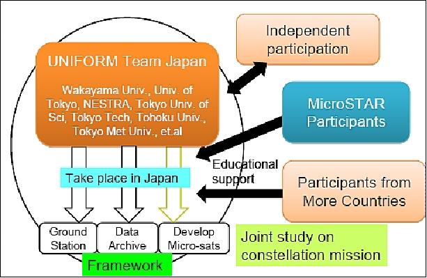
The UNIFORM project is a Japanese government-funded consortium of universities aiming to launch a constellation of scientific microsatellites. The project was initiated in the summer 2010 and formally announced at the APRSAF-17 (Asia-Pacific Regional Space Agency Forum) in Melbourne, Australia (Nov. 23-26, 2010). The UNIFORM project was approved by Japan's MEXT (Ministry of Education, Culture, Sports, Science and Technology) in October 2010. 1) 2) 3) 4) 5) 6) 7)
The overall objective of the UNIFORM project is to field a functional satellite constellation and ground station network that will yield usable data at a fraction of the price of commercially built satellites. More broadly, the project organizers expect UNIFORM to energize Japan's capacity for building microsatellites and spread that know-how throughout Asia through international cooperation. This network approach has the potential to change the space industry in the near future.
The UNIFORM consortium aims at initially launching groups of 50 kg class microsatellites in pairs or clusters in 2012 and 2014 to build a constellation capable of frequent revisits for Earth observation or atmospheric monitoring missions. - A major objective is to enrich the student training program on all levels, to stimulate interest in a problem-solving multi-disciplinary technical environment, to be imaginative and resourceful, and to take some risks – with ample and essential help from mentors and partners (industry, institutional, or otherwise). In general, a good amount of enthusiasm and lots of volunteer work by all parties involved are needed to bring such low‐cost program activities to maturity - an invaluable amount of professionalism is gained for all students in such programs.
The following Japanese universities and institutions are members of the UNIFORM consortium: Wakayama University (Wakayama, Japan), University of Tokyo, TITech (Tokyo Institute of Technology), University of Tohoku, Tokyo University of Science, Tokyo Metropolitan University, NESTRA (Next generation Space system Technology Research Association), Hokkaido University, Keio University, and JAXA.
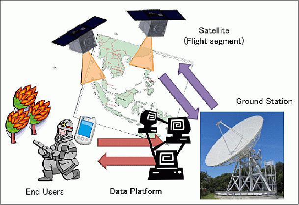
The overall theme selected for the UNIFORM-1 mission is forest fire monitoring. The yearly global emissions of CO2 amount to 29 billion tons and 15 billion tons of them are emitted by forest fire. Earth observation satellites can monitor the Earth globally; hence, the data from a mission like UNIFORM-1 can be used to help fighting those wild fires. This contributes not only for decreasing the amount of CO2 emission, but also saving people from disastrous fires. 8)
UNIFORM-1 system is comprised of four segments: Flight segment (satellite), ground segment, service segment and user segment. The data flow from satellite to end-user is shown on Figure 3. The process starts from the user segment requesting where and when to monitor, followed by the service segment to generate an operations plan based on the request. These two functions, as of now, have not been really developed so far as an automated system, but simply those who are interested in getting data request what to do and operation team discuss how to operate UNIFORM-1.
Spacecraft
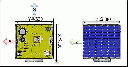
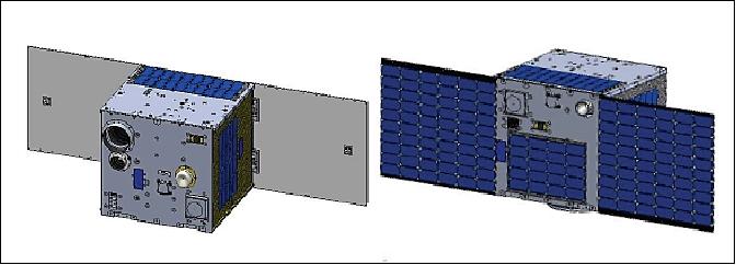
The microsatellite is based on a cubic bus structure of 50 cm side length with two deployable solar arrays and a launch mass of ~50 kg. The bus structure uses T-shaped panel supports providing accessibility to all of components and ease of integration. The microsatellite is designed to have a natural frequency of more than 100 Hz in the vertical direction of rocket (X-axis of satellite), and more than 50 Hz in the lateral direction of rocket (Y and Z axis of satellite).
There is no active thermal control function for the satellite body, although there are some heaters that locally control the temperature of components. Instead, MLI is attached on the ±X and ±Z panels to prevent the satellite from excessive heating or cooling loads, while the ±Y panel is blackened to release body heat to the outside (heated by components power consumption inside).
The microsatellite is 3-axis stabilized. The ADCS (Attitude Determination and Control Subsystem) uses four reaction wheels and 3 magnetic torquers as attitude control actuators; the attitude is sensed by sun sensors, a geomagnetic sensor, a fiber optic gyro, a star tracker and a GPS receiver.
Device name | Mass and size | Power | Specification |
NSAS (Non-Spin Sun Sensors) | 46 g, 31 x 50 x 22 mm | 5 V, 150 mW | RS422, ~1º accuracy |
GAS (Geomagnetic Sensor) | 320 g, 95 x 95 x 45 mm | 5 V, 30 mA | Analog out ±100000 nT range, 4000 nT/V |
FOG (Fiber Optic Gyroscope) | 1 kg, 135 x 150 x 45 mm | 28 V, 120 mA | RS422 and analog ±5º range, 400mV/º /s, <0.01º/s noise |
STT (Star Tracker) | 510 g, 147 x 80 x 77 mm | 28 V, 2.5 W | RS422, 2Hz output accuracy: 30 arcsec (Y, Z), 0.04º (X) |
GPSR (GPS Receiver) | 400 g, 98 x 98 x 22 mm | 5 V, 180 mA | RS422, 1 Hz |
RW (Reaction Wheels) | 1.1 kg, 120 x 120 x 64 mm | 28 V(motor), 5 V(controller) | RS422, >0.003 Nm @4000 rpm |
MTQ (Magnetic Torquers) | 375 g, 176 x 54 x 47 mm | 5 V, 70 mA | 5 AM2 ±20% |
There are four ADCS modes in addition to a mode that does nothing for control but telemetry and command handling. These are:
1) SSP (Spin Sun Pointing) mode
2) CSP (Coarse Sun Pointing) mode
3) CEP (Coarse Earth Pointing) mode
4) FEP (Fine Earth Pointing) mode.
After deployment of the microsatellite, the SSP mode is used. In terms of the power budget, it is planned to use the CSP mode as the nominal mode.
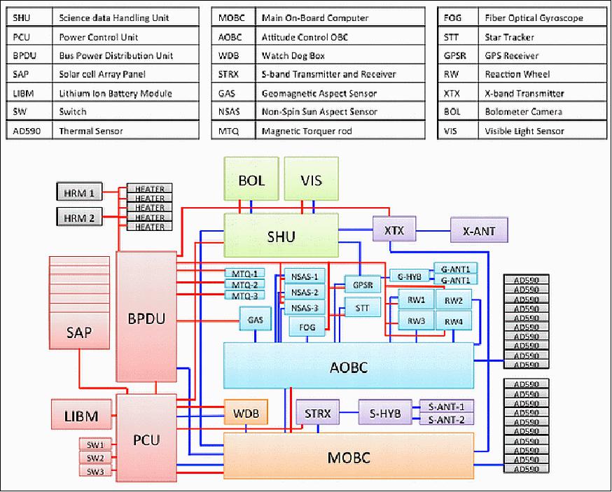
OBC (OnBoard Computers): There are three onboard computers: MOBC (Main On-Board Computer), AOBC (Attitude control On-Board Computer) and SHU (Science data Handling Unit).

C&DH (Command and Data Handling Subsystem) subsystem: The C&DH is comprised of MOBC, WDB (Watch Dog timer Box) and part of AOBC. The main functions of C&DH are to handle command from the ground, to collect data from other components, to manage the satellite mode, and to watch the under voltage control of the battery. The C&DH includes the platform software of both MOBC and AOBC, all tasks are managed by the realtime operating system. Onboard communications between the components are through RS-422 interfaces; the network structure of the OBC is implemented in a star configuration.
EPS (Electrical Power Subsystem): EPS is comprised of a PCU (Power Control Unit), BPDU (Bus Power Distribution Unit), a Li-ion battery module, and solar array panels. The battery module consists of 8series and 2 parallel cells and inner circuit controls, voltage balancing and an over-charge protection mechanism. The battery voltage and capacity are 23.0-33.2 V and 6200 mAh, respectively.
The solar cells are GaInP2/GaAs/Ge triple junction type; a single cell size is 80 x 40 mm with a mass of 2.6 g, generating 1 W at 2.0 V in 80ºC. There are 20 cells in series providing 33.2 V max. The solar cells are face-mounted to the satellite body and to the wings.
RF Communications: Use of an S-band and X-band communication system. The S-band is used for TT&C data with a data rate of 64 kbit/s (max). The X-band transmit the science data at a rate of 10 Mbit/s (max).
STRX (S-band Transmitter and Receiver) | Selectable data rate: 4, 16, 32, 64 kbit/s |
S-ANT (S-band Antenna) | 2 antennas, 74º beamwidth, mass: 107 g |
XTX (X-band Transmitter) | Selectable data rate: 1.25, 2.5, 5, 10 Mbit/s |
X-ANT (X-band Antenna) | Max gain at ±60º, mass: 151 g |
Spacecraft mass, size | ~49 kg, 50 cm x 50 cm x 50 cm |
Sensor complement | Microbolometer Array Sensor, Visible Light Camera |
OBC (OnBoard Computer) | SOI-SOC OBC, SH-4 processor |
EPS (Electrical Power Subsystem) | SAP generation: 140W (max) |
ADCS (Attitude Determination and Control Subsystem) | - GPS receiver, sun sensors, star tracker, fiber optics gyroscope, magnetometer |
RF communications | - S-band: downlink = 64 kbit/s, uplink = 4 kbit/s |
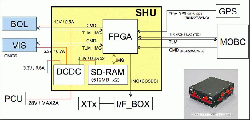
SHU (Science data Handling Unit): The objective of SHU is to control the BOL and VIS cameras, store the image data and send it via the X-band transmitter. Figure 9 shows the architecture of mission subsystem. SHU provides also power to cameras; the power is originally provided from the PCU (Power Control Unit). The image data is stored on SDRAM (512 MB) without compression. SHU stores not only image data but also HK data of SHU and that of the other computers.
Launch
The UNIFORM-1 microsatellite was launched as a secondary payload on May 24, 2014 (03:05:14 UTC) on a H-IIA F24 vehicle (No 24) from the Yoshinobu Launch Complex at TNSC (Tanegashima Space Center), Japan. The launch provider was MHI (Mitsubishi Heavy Industries, Ltd.). The primary payload on this flight was the ALOS-2 spacecraft of JAXA.
The secondary missions manifested on the ALOS-2 mission by JAXA are: 9)
• SPROUT (Space Research on Unique Technology), a nanosatellite of ~7 kg of Nihon University, Tokyo, Japan.
• Rising-2, a cooperative microsatellite (43 kg) project of Tohoku University (Sendai) and Hokkaido University, Sapporo, Japan.
• UNIFORM-1 (University International Formation Mission-1), a microsatellite (~50 kg) of Wakayama University, Wakayama, Japan.
• SOCRATES (Space Optical Communications Research Advanced Technology Satellite), a microsatellite (~ 50 kg) mission of NICT (National Institute of Information and Communications Technology), Koganei, Japan.
Orbit
Sun-synchronous near-circular sub-recurrent orbit, altitude = 628 km, inclination = 97.9º, period = 97.4 minutes, revisit time = 14 days, number of orbits/day = 15 3/14, LSDN (Local Sun time on Descending Node) = 12:00 hours ± 15 min.
Mission Status
• August 2015: The UNIFORM-1 program ended at the end of March 2015, but its operations continue with efforts of the project members. During and after the program period, by capturing various mission data around the world, UNIFORM-1 demonstrated that a microsatellite can perform the task in observing heat anomalies from the ground, by capturing useful data in several critical events such as wildfires and volcanic activities. It is expected that by increasing the number of microsatellites with similar specifications, more useful observations will be possible on those critical events by delivering more time-responsive information. The project members will continue the effort of constructing a constellation, while maintaining UNIFORM-1 operations. 10)
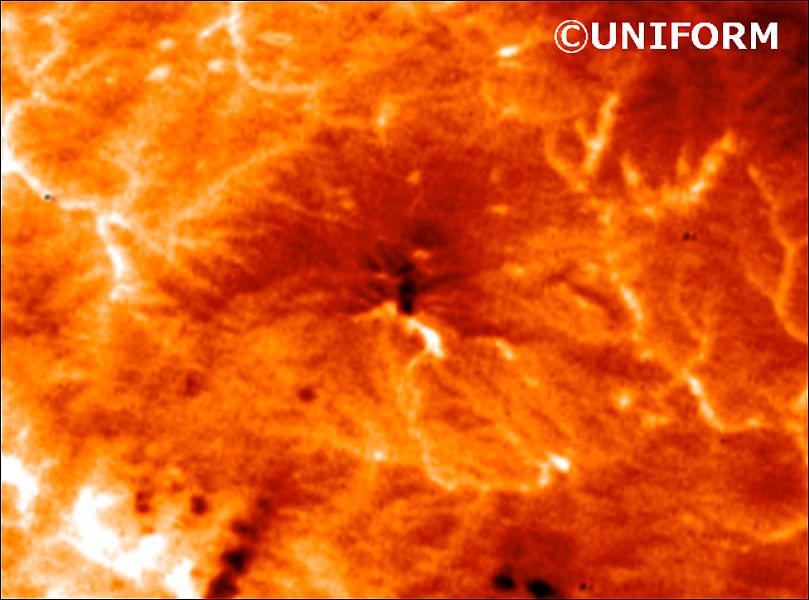
• A volcanic eruption of Mount Ontake, Nagano, Japan, took place on September 27, 2014, killing 57 people. Mount Ontake is a volcano located on the Japanese island of Honshu around 100 km northeast of Nagoya and around 200 km southwest of Tokyo.
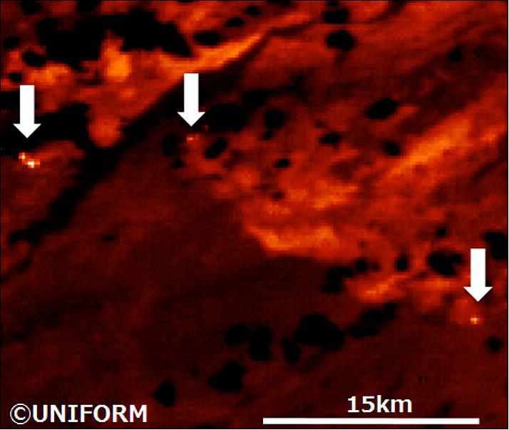
• On August 20, 2014, the UNIFORM-1 BOL instrument captured images of the Tetachuck lake area in British Columbia, Canada, and identified forest fire. This observation, as shown in Figure 12, was motivated by the knowledge of existing forest fire and was to verify the wildfire monitoring capability of UNIFORM-1.
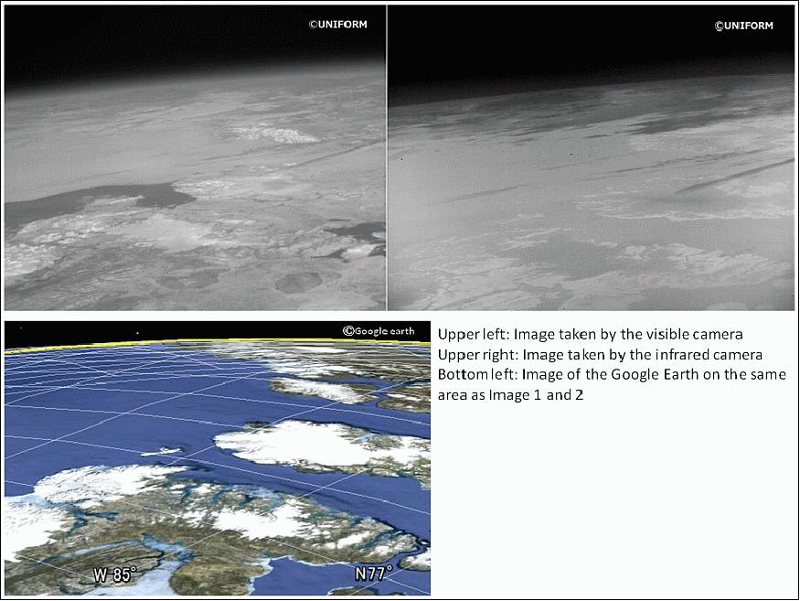
• On July 9, 2014 imagery was acquired at 12:04 PM JST (03:04 UTC) above the Arctic. The satellite cameras automatically took pictures at the scheduled time which was preset. Coburg Island, Canada, other islands and ice fields are seen in the pictures. 11)
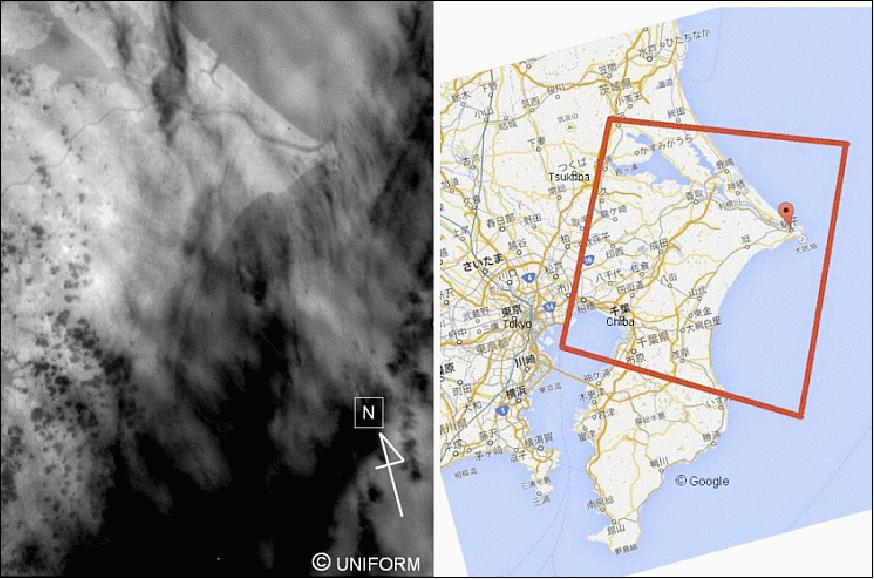
• On May 28, 2014, the first image of the BOL camera on UNIFORM-1 was acquired at 02:52 UTC, corresponding to 11:52 JST (Ref. 8).
• On May 26, 2014, the SAP (Solar Array Panel) wings of the microsatellite were deployed on command from the ground station. Next, the attitude control was activated by transitioning to the SSP (Spin Sun Pointing) mode.
• The first data acquisition at the Wakayama University ground station was 04:45:48 UTC on May 24, 2014. The information from the satellite was successfully received and all of the HK (Housekeeping) information was in a good state (Ref. 8).
Sensor Complement
The UNIFORM-1 microsatellite carries two cameras looking into the same target area; one is a microbolometer camera, which is an uncooled thermal infrared camera for detecting heat anomaly spot on the ground, and the other is visible light camera, which supports position identification of the ground image (Ref. 8).
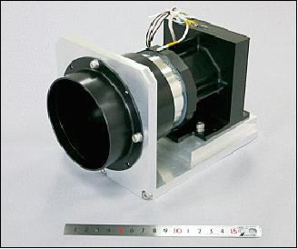
BOL (Bolometer Camera)
The camera features a microbolometer with an uncooled 2D array thermal infrared sensor. The objective is to detect thermal spots on the ground as distinguished from other surface imagery. However, forest fire identification is not computed on-board but rather on the ground, after imagery of the bolometer camera is received without any image corrections.
Detector | UL04171 (ULIS France) |
Spectral range | 8-14 µm |
Active pixels | 640(H) x 480 (V) |
Pixel size | 25 µm |
Detector size | 16.0 mm x 12.0 mm |
Data size | 614.4 kB |
Frame rate | 60 Hz |
NEDT (Noise Equivalent Differential Temperature) | 0.12 K@ 300 K, f/1 |
Absolute temperature accuracy | ±3 K |
Spatial resolution | 0.0143º/pixel, corresponding to 157 m/pixel @ 628 km |
FOV (Field of View) | 9.17º (H) x 6.88º (V), corresponding to 100.5 km x 75.4 km |
Power | 7.0 V, 1.8 A |
Camera size | 100.0 x 100.0 x 123.0 mm |
Camera mass | 800 g |
Ge lens | Ophir65148, F=100 mm, F/1.4 |
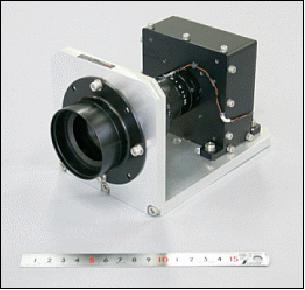
VIS (Visible Camera)
The VIS camera serves for position identification providing the some coverage as the BOL camera. The spatial resolution is < 100 m.
Detector | VITA1300 (on semiconductor) |
Spectral range | 400 - 1000 nm |
Active pixels | 1280 (H) x 1024 (V) |
Pixel size | 4.8 µm |
Detector size | 6.14 mm x 4.92 mm |
Data size | 2.63 MB |
Frame rate | 150 Hz |
Spatial resolution | 0.0079º/pixel, corresponding to 86.1 m/pixel @ 628km |
FOV (Field of View) | 10.6º (H) x 8.05º (V), corresponding to 110.2 km x 88.2 km |
Instrument mass, size | 580 g, 90.5 x 90.5 x 95.5 mm |
Ge lens | JHF50MK, F=35 mm, F/1.4 |
Ground Segment
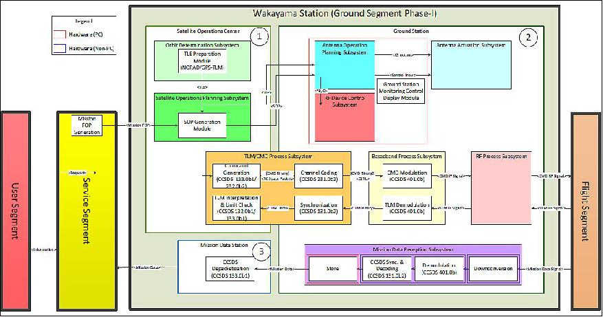
A dedicated ground station (GS) was developed at Wakayama University, Wakayama, Japan. The ground station has a 3 m antenna for S-band CMD/TLM communications and a 12 m antenna for X-band mission for data downlink.Figure 17 shows a small cabin next to a 12 m antenna for mission data downlink. Currently this is where the entire satellite operations are performed. There is also a 3 m antenna for S-band uplink/downlink, which is located adjacent to the 12 m antenna. 12)
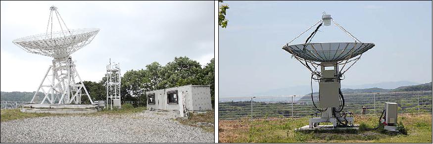
Figure 2 shows the four segments of UNIFORM-1 with the functional block diagram of the UNIFORM-1 ground station emphasized in the center.
References
1) Paul Kallender-Umezu, "Japan Advances University-led Microsatellite Constellation," Space News, Dec. 3, 2010, URL: http://www.spacenews.com/article/japan-advances-university-led-microsatellite-constellation
2) Kanenori Ishibashi, Shinichi Nakasuka, Hiroaki Akiyama, "MEXT's Program called UNIFORM;" APRSAF-17 (17th Session of the Asia-Pacific Regional Space Agency Forum), Melbourne, Australia, Nov. 23-26, 2010, URL: http://www.aprsaf.org/data/aprsaf17_data/D4-0940_4_S_NAKASUKA.pdf
3) Shigekazu Matsuura, "Overview of Japanese Activities for Education and Capacity Development in the Space Field," APRSAF-17 (17th Session of the Asia-Pacific Regional Space Agency Forum), Melbourne, Australia, Nov. 23-26, 2010, URL: http://www.aprsaf.org/data/aprsaf17_data/D4-0940_1_S_Matsuura.pdf
4) Masahiko Nagai, "JAXA's Present Capacity Building Activities for the Asia-Pacific Region," APRSAF-17 (17th Session of the Asia-Pacific Regional Space Agency Forum), Melbourne, Australia, Nov. 23-26, 2010, URL: http://www.aprsaf.org/data/aprsaf17_data/D4-0940_2_M_Nagai.pdf
5) Kyoichi Ito, "Remote Sensing Training & Capacity Building," APRSAF-17 (17th Session of the Asia-Pacific Regional Space Agency Forum), Melbourne, Australia, Nov. 23-26, 2010, URL: http://www.aprsaf.org/data/aprsaf17_data/D4-0940_3_K_Ito.pdf
6) http://www.wakayama-u.ac.jp/ifes/uniform/
7) Shusaku Yamaura, Robin Landzaat, Koki Kamiya, Kikuko Miyata, Seiko Sashirasaka, Kanenori Ishibashi, "Efficient Software Verification Process along with Newly Designed Software Architecture," Proceedings of the UN/Japan Workshop and The 4th Nanosatellite Symposium (NSS), Nagoya, Japan, Oct. 10-13, 2012, paper: NSS-04-0103
8) Shusaku Yamaura, Seiko Shirasaka, Takashi Hiramatsu, Miki Ito, Yuta Araki, Kikuko Miyata, Tomomi Otani, Naoko Sato, Hiroaki Akiyama, Tetsuya Fukuhara, Koji Nakau, Yoshihiro Tsuruda, Jun'ichi Takisawa, Shinichi Nakasuka, Kohei Tanaka, Keisuke Maeda, "UNIFORM-1: First Micro-Satellite of Forest Fire Monitoring Constellation Project," Proceedings of the AIAA/USU Conference on Small Satellites, Logan, Utah, USA, August 2-7, 2014, paper: SSC14-VI-2, URL: http://digitalcommons.usu.edu/cgi/viewcontent.cgi?article=3101&context=smallsat
9) Toshinori Kuwahara, Kazaya Yoshida, Yuji Sakamoto, Yoshihiro Tomioka, Kazifumi Fukuda, Nobuo Sugimura, Junichi Kurihara, Yukihoro Takahashi, "Space Plug and Play Compatible Earth Observation Payload Instruments," Proceedings of the 9th IAA Symposium on Small Satellites for Earth Observation, Berlin, Germany, April 8-12, 2013, Paper: IAA-B9-1502, URL: http://media.dlr.de:8080/erez4/erez?cmd=get&src=os/IAA/archive9/Presentations/IAA-B9-1502.pdf
10) Takashi Hiramatsu, Shusaku Yamaura, Hiroaki Akiyama, Naoko Sato, Katsumi Morita, Tomomi Otani, Kikuko Miyata, Toru Kouyama, Soushi Kato, Miki Ito, Yuta Araki, " Early Results of a Wildfire Monitoring Microsatellite UNIFORM-1," Proceedings of the 29th Annual AIAA/USU Conference on Small Satellites, Logan, Utah, USA, August 8-13, 2015, paper: SSC15-IX-2, URL: http://digitalcommons.usu.edu/cgi/viewcontent.cgi?article=3225&context=smallsat
11) http://www.wakayama-u.ac.jp/ifes/uniform/
12) Takashi Hiramatsu, Shusaku Yamaura, Tomomi Otani, Naoko Sato, Katsumi Morita,Toru Koyama, Kikuko Miyata, "UNIFORM-1 Ground System: Mission Planning, Scheduling, Control, and Data Processing," Proceedings of the 28th Annual AIAA/USU Conference on Small Satellites, Logan, Utah, USA, August 2-7, 2014, paper: SSC14-II-1, URL: http://digitalcommons.usu.edu/cgi/viewcontent.cgi?article=3022&context=smallsat
The information compiled and edited in this article was provided by Herbert J. Kramer from his documentation of: "Observation of the Earth and Its Environment: Survey of Missions and Sensors" (Springer Verlag) as well as many other sources after the publication of the 4th edition in 2002. - Comments and corrections to this article are always welcome for further updates (eoportal@symbios.space).
Overview Spacecraft Launch Mission Status Sensor Complement Ground Segment References Back to top