Aeolus / formerly ADM (Atmospheric Dynamics Mission)
EO
ESA
Lidars
Atmosphere
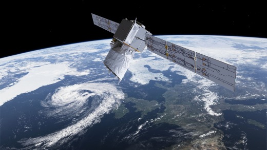
Aeolus (or ADM-Aeolus) was an Earth Observation mission, named after the ruler of winds from Greek mythology. The satellite was the first to acquire profiles of Earth’s wind on a global scale.
Quick facts
Overview
| Mission type | EO |
| Agency | ESA |
| Mission status | Mission complete |
| Launch date | 22 Aug 2018 |
| End of life date | 30 Apr 2023 |
| Measurement domain | Atmosphere |
| Measurement category | Cloud type, amount and cloud top temperature, Cloud particle properties and profile, Aerosols, Atmospheric Winds |
| Measurement detailed | Cloud top height, Cloud optical depth, Aerosol Extinction / Backscatter (column/profile), Wind profile (vertical) |
| Instruments | ALADIN |
| Instrument type | Lidars |
| CEOS EO Handbook | See Aeolus / formerly ADM (Atmospheric Dynamics Mission) summary |
Related Resources
Summary
Mission Capabilities
ADM-Aeolus carried onboard the Atmospheric Laser Doppler Instrument (ALADIN) developed by Airbus Defence and Space (Airbus DS). ALADIN provides global observations of wind profiles with a vertical resolution that satisfies the accuracy requirements of the World Meteorological Organization (WMO). The provision of accurate wind profiles in the troposphere and lower stratosphere eliminates a major deficiency in the Global Observing System and directly contributes to the study of Earth’s global energy budget.
Its secondary mission objectives related to the provision of data sets for model variation and short term wind climatologies. This enabled understanding of atmospheric dynamics, including the global transport of energy, water, aerosols, chemicals and other airborne materials, to be used to deal with many aspects of climate research, climate and weather prediction. ADM-Aeolus measurements were also assimilated into existing numerical forecasting models, in order to enhance the quality of operational short and medium-range predictions.
Performance Specifications
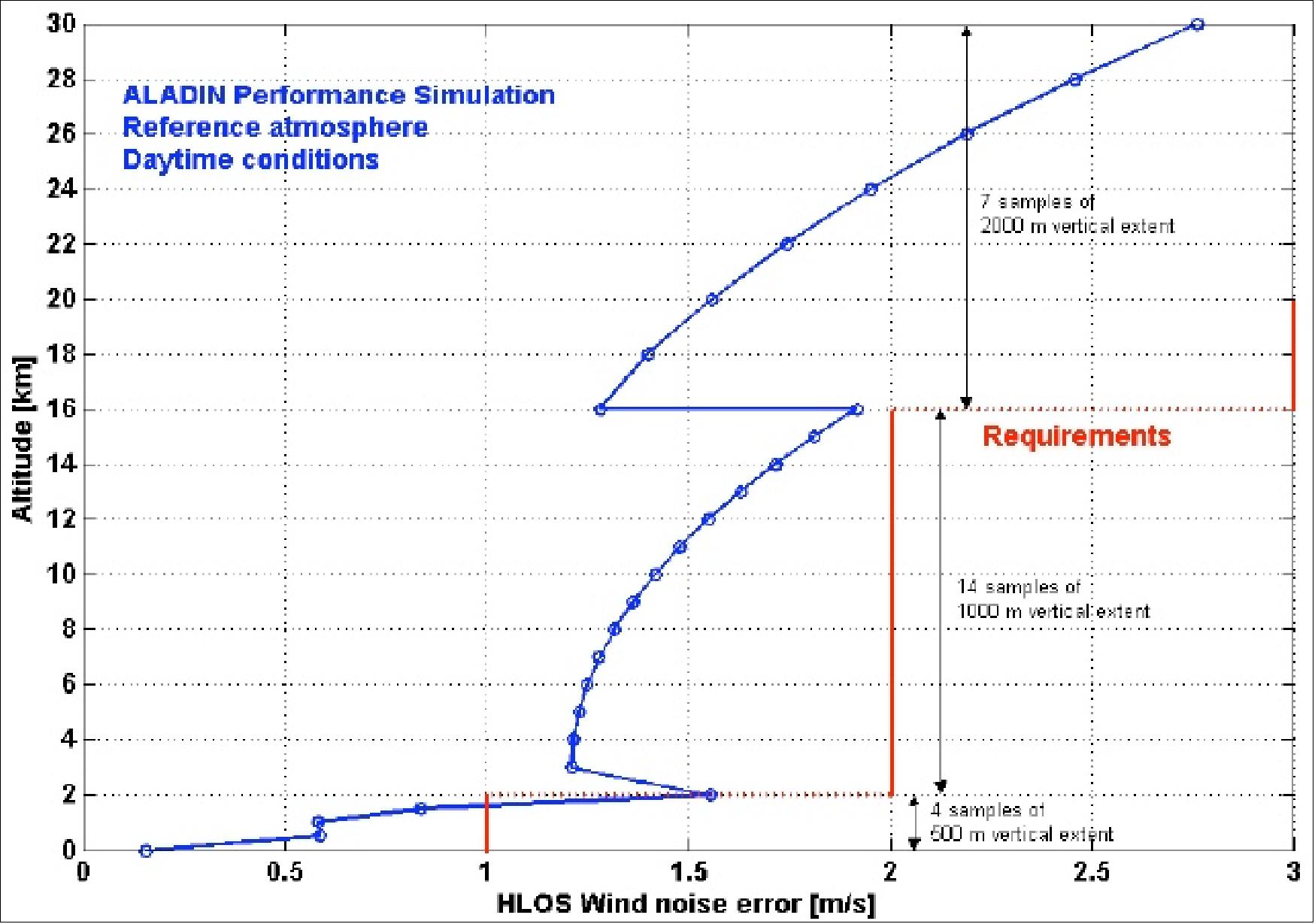
ALADIN was able to provide data for a wind velocity range of -150 to 150 m/s in three parameters; the Planetary Boundary Layer (PBL), troposphere and lower stratosphere. For the PBL, lying 0 - 2 km above Earth’s surface, ALADIN produced a vertical resolution of 0.25 km. In the troposphere, 2 - 16 km above Earth’s surface, and the stratosphere, 16 - 26 km above Earth’s surface, the instrument provides vertical resolutions of 1 km and 2 km respectively.
ALADIN could produce 100 profiles per hour, covering a horizontal domain of 80°S to 85°N. The excellent horizontal and vertical sampling capabilities of the instrument, combined with a continuous availability of its data products within three hours after sensing, enhanced the quality of current operational short- and medium-range predictions.
ALADIN employed the Doppler Wind Lidar measurement technique, where the retrieval of wind speed relied on direct measurement along the LOS (Line-of-Sight) by lidar using Doppler shift information from atmospheric molecules and particles advected by wind.
ADM-Aeolus underwent a sun-synchronous orbit at a mean altitude of 320 km with an inclination of 96.97°. The satellite had a period of 92.5 minutes, a repeat cycle of seven days and a local equator crossing time at 1800 hours on an ascending node and at 0600 hours for a dawn-dusk orbit.
Space and Hardware Components
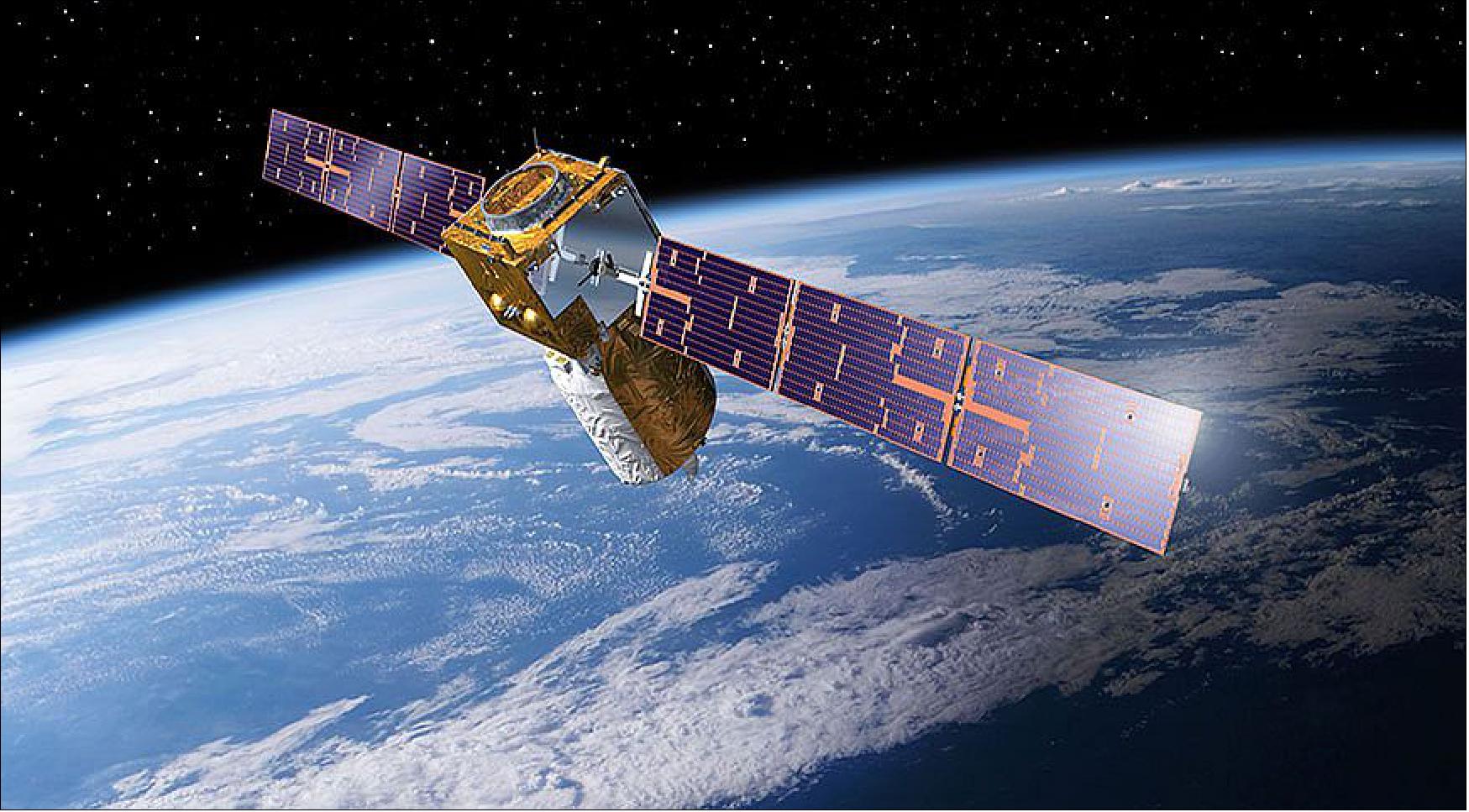
Developed by Airbus DS with a design life of four years, the ADM-Aeolus satellite bus was a new design based on a heritage from other Airbus DS developments including CryoSat and Rosetta.
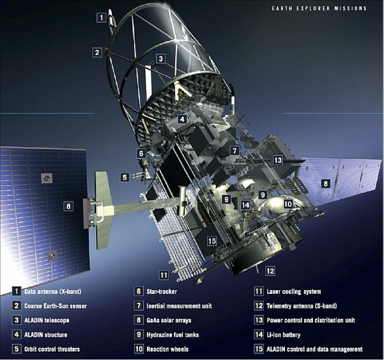
The spacecraft featured a conventional box-shaped bus consisting of aluminium honeycomb elements, upon which ALADIN was mounted via three isostatic bipods. The 1360 kg spacecraft was three-axis stabilised with an AOCS (Attitude and Orbit Control Subsystem). It used thrusters, reaction wheels and magnetorquers as actuators, and magnetometers, coarse Earth sun sensors, inertial measurement units, rate measurement units, AST (Autonomous Star Tracker) and a GPS receiver as sensors. The orbit was maintained by 5 N hydrazine thrusters.
Aeolus / formerly ADM (Atmospheric Dynamics Mission)
Spacecraft Launch Mission Status Sensor Complement Ground Segment References
Aeolus was an ESA (European Space Agency) Earth Explorer Core Mission -a science-oriented mission within its Living Planet Program.
The primary objective was to provide wind profile measurements for an improved analysis of the global three-dimensional wind field. The aim of the mission was to provide global observations of wind profiles with a vertical resolution that could satisfy the accuracy requirements of WMO (World Meteorological Organization).
Such knowledge was crucial to the understanding of the atmospheric dynamics, including the global transport of energy, water, aerosols, chemicals and other airborne materials - to be able to deal with many aspects of climate research and climate and weather prediction. ADM-Aeolus represented a demonstration project for the Global Climate Observing System (GCOS). 1) 2) 3) 4) 5) 6) 7) 8) 9) 10) 11) 12) 13)
The measurement data allowed achievement of the primary goals of Aeolus:
- Provision of accurate wind profiles throughout the troposphere and lower stratosphere eliminating a major deficiency in the Global Observing System
- Direct contribution to the study of the Earth's global energy budget
- Provision of data for the study of the global atmospheric circulation and related features, such as precipitation systems, the El Niño and the Southern Oscillation phenomena and stratospheric/tropospheric exchange.
The secondary mission objectives were related to the provision of data sets for model variation and short-term "windclimatologies" that allowed experts to:
- Validate climate models through the use of high quality wind profiles from a global measurement system
- Improve their understanding of atmospheric dynamics and the global atmospheric transport and cycling of energy, water, aerosols, chemicals and other airborne materials.
- Generate a number of derived products such as cloud top altitudes, aerosol properties and tropospheric height.
The ADM-Aeolus measurements were assimilated in numerical forecasting models, in order to enhance the quality of operational short- and medium-range predictions. Expected improvements were mainly due to the excellent horizontal and vertical sampling capabilities of the instrument, combined with a continuous availability of its data products within 3 hours after sensing.
Note: In the works of the Greek poet Homer, Aeolus is the controller of the winds and ruler of the floating island of Aeolia. In the Odyssey, he gave Odysseus a favorable wind and a bag in which the unfavorable winds were confined. Odysseus' companions opened the bag; the winds escaped and drove them back to the island. Although he appears as a human in Homer, Aeolus later was described as a minor god.
The ADM-Aeolus mission used a single observation instrument, namely ALADIN (Atmospheric Laser Doppler Instrument), employing the DWL (Doppler Wind Lidar) measurement technique. The retrieval of wind speed relied on direct measurement along the LOS (Line-of-Sight) by lidar using Doppler shift information from atmospheric molecules and particles advected by wind. The ALADIN observations served as input for NWP (Numerical Weather Prediction) models. An extensive pre-development evaluation and assessment program of ALADIN laser component technology was started in 2000.
ADM-Aeolus was seen as a pre-operational mission, demonstrating new laser technology and paving the way for future meteorological satellites to measure the Earth's wind.
Spacecraft
Although the ADM-Aeolus satellite was a new design, the platform was based on a heritage from other ESA missions developed by Airbus DS (former EADS Astrium) including CryoSat, and Rosetta. The aim was to build a spacecraft that was relatively simple to operate. This reduced the operating costs throughout its lifetime, and was also important for the future since similar Aeolus-type satellites were later envisaged for operational use.
The S/C structure, which consisted of aluminum honeycomb elements, used a conventional box-shaped spacecraft design (derived from Mars Express), upon which the observation instrument was mounted via three isostatic bipods. The electronic boxes of the bus and the associated satellite equipment were mounted on the side panels.
The spacecraft was three-axis stabilized with AOCS (Attitude and Orbit Control Subsystem), using thrusters, reaction wheels and magnetorquers as actuators, and magnetometers, coarse Earth sun sensors, inertial measurement units, rate measurement units, AST (Autonomous Star Tracker), and a GPS receiver as sensors. The orbit was maintained by 5 N thrusters. 14)
Type | Equipment | Nr. | Main characteristics | Technology | Redundancy | Use |
Sensors | Magnetometer | 2 | Three-axis | Anisotropic magneto-resistor | Cold redundancy | Nominal and safe mode |
Coarse Earth sun sensor | 1 | 4 pi steradian FOV | Thermal | Internal (2 of 3) | Nominal and safe mode | |
GPS receiver | 2 | C/A GPS receiver | RF ASIC and micro processor | Cold redundancy | Nominal mode | |
Autonomous star tracker (AST) | 2 | Large FOV | CCD | Cold redundancy | Nominal mode | |
Rate Measurement Unit | 1 | 3 measurement axes | Solid-state rate sensor | None | Safe mode | |
Inertial reference unit (IRU) | 1 | 3 measurement axes | Fiber Optic Gyro | Internal (3 of 4) | Nominal mode | |
Actuators | Reaction wheels | 4 | 10 Nms/0.1 Nm | Ball bearings | 3 of 4 | Nominal mode |
Magnetic torquers | 3 | 100 Am2 | Windings | Cold redundancy | Nominal and safe mode | |
Thrusters | 4 | 5 N | Hydrazine | Cold redundancy | Orbit control and safe mode |
Magnetometer: The magnetometer (developed at LusoSpace, Portugal) of the ADM-Aeolus spacecraft employed the AMR (Anisotropic Magneto Resistive) technology. The rationale for using the AMR detector for the magnetometer development was due to several advantages over fluxgate technology: 15)
- Detector production repeatability
- Lower cost
- Easier integration in a PCB (Printed Circuit Board)
- Possibility to generate external magnetic field in the chip by mean of built in coils.
The magnetometer was a small (credit card surface dimension) and robust unit that could be used for several LEO missions. Two flight models of the magnetometer were flown on ADM-Aeolus. In addition, a qualification model flied on PROBA-2 as a passenger to provide more flight heritage and in orbit data.
Dynamic field range | ±70 000 nT |
Noise (2σ) | < 40 nT |
Offset (after calibration), offset deviation (-10ºC to 50 ºC) | < 300 nT, < 200 nT |
Linearity | < 0.05 % (full scale: ±70 000 nT) |
Bandwidth | up to 40 Hz (adjustable) |
Design life | 4 years in LEO orbit |
Instrument mass, power, size | 300 g, 1 W, 85 mm x 53 mm x 60 mm (excl. connectors) |

EPS (Electric Power Subsystem): Electric power was provided by two deployable solar wings of 14.5 m2 of total surface area. The triple-junction GaAs cells of the solar arrays provided over 2.4 kW of power (with 1.4 kW of average power required). The solar arrays were articulated toward the sun to optimize their power output. Use of SADM (Solar Array Drive Mechanism) for attitude regulation of the wings. The design included a standard PCDU (Power Control and Distribution Unit) responsible for solar array power conditioning and distribution. A Li-ion battery of 64 Ah capacity was used for eclipse phases and LEOP (Launch and Early Orbit Phase). 16)
On-board autonomy: The spacecraft was designed to include a large amount of on-board autonomy in all mission phases such that ground contact was needed no more than once every 5 days even in the case of anomaly.
On-board data handling was performed by an ERC-32 radiation tolerant processor with 6 MByte system RAM. The subsystems were linked via MIL-STD-1533 data bus to the central processor. A solid-state memory provided a capacity of 8 Gbit on-board data storage.
Aeolus was conceived to allow simple in-flight operation. The satellite had a five-day autonomy in case of any single onboard failure, so that a single operator shift was sufficient to monitor the satellite. In addition, the orbit had a seven day repeat cycle, so that the complete operations timeline was repeated on a weekly cycle, thus minimizing the effort for mission planning.
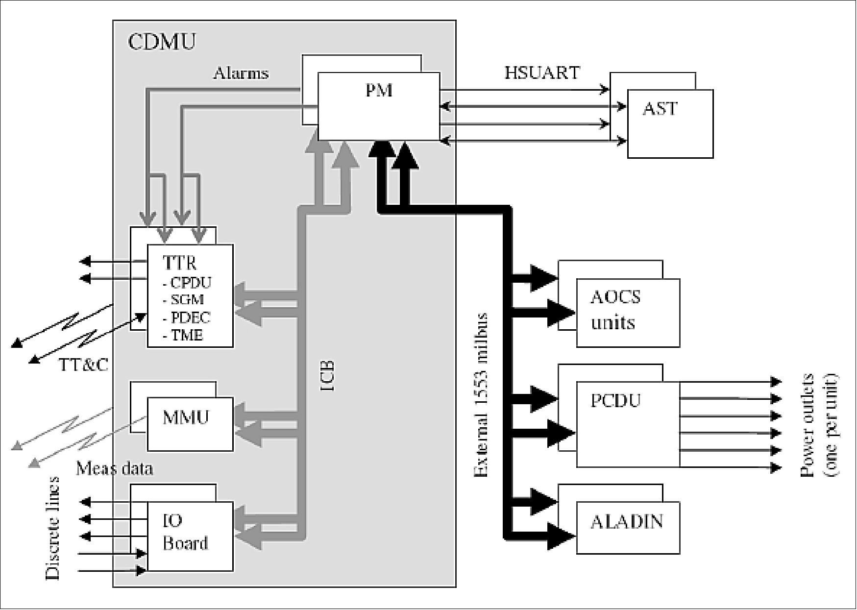
At the heart of the avionics architecture were the CDMU (Command and Data Management Unit) manufactured by RUAG, Sweden and the PCDU (Power Conversion and Distribution Unit) manufactured by Patria, Finland. 17) 18)
The CDMU included redundant processor modules interfaced by a MIL-STD-1553 bus protocol based ICB to IO boards providing input / output services including thruster drivers, mass memory units for measurement data storage and the TTR (Telemetry Telecommand and Reconfiguration) boards incorporating, telecommand packet decoders, telemetry encoders, RMs (Reconfiguration Modules) and SGM (Safe Guard Memory). The RMs monitor alarms generated autonomously within the PM (Processor Module) or from the APSW (Application Software) and performed reconfiguration and restart of the PMs accordingly.
The SGM was a permanently powered memory used to preserve data during PM reconfigurations and restarts. Each PM had two software images stored in non-volatile memory, a nominal mode image and a safe mode image. The RMs selected which image to download into RAM and execute.
Except for the AST (Autonomous Star Tracker) subsystem, the CDMU was interfaced to all external units either via discrete lines provided by the IO boards or via an external MIL-STD-1553 bus. Each PM included separate bus controllers allowing the active PM to control both the ICB (Internal Control Bus) and the external MIL-STD-1553 bus independently. The AST, manufactured by Terma in Denmark, was interfaced directly to each PM via an RS422 HSUART (High Speed Universal Asynchronous Receiver Transmitter).
The PCDU, which interfaced to the CDMU via the external Mil-STD-1553 bus, provided regulated and unregulated power outlets, shunt and battery charge control, solar array deployment thermal knife control and individually switched heater lines for thermal control.
The power outlets supplying the TT&C receivers and the reconfiguration units were non-switchable and were protected by FCLs (Foldback Current Limiters). All other outlets were switched and protected by LCLs (Latching Current Limiters). The shunt regulation and battery charge control were fully implemented in the PCDU electronics and required no involvement from ground or the on-board software under both nominal and failure conditions. Thermal knife drivers and deployment micro-switch status acquisition and conditioning were provided to support solar array deployment.
On-board autonomy architecture: One of the simplest methods to achieve on-board autonomy was to implement an on-board schedule that was loaded fully under ground responsibility.
Such an autonomy approach was straight forward to test and validate since only basic functionalities such as command insertion, command deletion and command execution at scheduled time had to be tested. In particular there was no need to develop and test any logic relating one command to another and there was no need to develop and test any logic for selecting which commands to schedule. This was the approach adopted for ADM-Aeolus with two simple schedules being implemented, one based on time and the other based on orbit position.
Although this approach worked well under nominal circumstances, it was not tolerant to failures that occur in the system such that, by the time the commands were due for execution, they were no longer valid or allowed. In particular such a system design approach was vulnerable to the following:
1) The scheduled commands addressing a physical unit that has failed and has been replaced by its redundant unit.
2) A scheduled command failing to execute successfully because a reconfiguration is occurring.
3) Commands to one unit being only allowable if another unit or subsystem is in a particular state and must not be executed if this condition is not met.
4) Scheduled commands being part of a functional sequence of commands and so dependending on the successful execution of previous scheduled commands.
5) Complex critical operations, such as solar arrays deployment, requiring the execution of decision branches and had to be executed even if the CDMU was reconfigured or restarted.
During the design stage the potential vulnerability of the AEOLUS scheduled operations to the above cases was assessed and the solutions taken to avoid them (Ref. 17).
FDIR (Failure Detection, Isolation and Recovery):
The overall FDIR concept adopted in Aeolus was driven by the objective to minimize ground intervention both during nominal operations and in failure scenarios.
The autonomous multi-layer FDIR architecture had to include monitors to identify all failures that:
- Directly endangered the unit itself or risk propagation to other units as identified in the Satellite and lower level FMECAs (Failure Modes and Effects Criticality Analysis)
- Corrupted or significantly degraded functions necessary for the correct functioning of the spacecraft in the current spacecraft mode / configuration [these failures might have been identified in the FMECAs and HSIAs (Hardware Software Interaction Analysis) or might have been "feared events"]
- Corrupted or significantly degraded functions necessary for data dissemination to the ground.
A high speed FDIR MIL-STD-1553 bus was established to monitor bus protocol status messages to identifying a loss of communication and allowing start of recovery within 1 second. For each unit, feared events were identified based on the function of the unit in the overall design and also based on the satellite and unit FMECA and HSIA documents (Ref. 17).
The Aeolus FDIR concept was built around top-down onboard control architecture: (Ref. 12)
• At the highest level hot redundant TTR(TM, TC and Reconfiguration) boards within the CDMU contained Reconfiguration Modules which oversaw the health and function of the CDMU and flight software by monitoring hardware alarm inputs and performing CDMU resets, reconfigurations and switches to Safe Mode as appropriate.
• At the next level the CDMU application software monitored and controlled the spacecraft units by monitoring on board parameters and autonomously sending control commands in response to parameter out of range events.
• At the lowest level some units performed their own built-in health checks and reported this through the TM to the CDMU software.
For the platform functions, the FDIR needed to ensure that the spacecraft could safely recover from single level failures either by resuming operations autonomously or by switching to predefined redundant configurations. For ALADIN, the FDIR needed to ensure instrument safety by both stopping scheduled operations and switching the instrument into a safe and stable configuration or by switching ALADIN into Survival mode.
Redundancy princple: In case of on-board failure detection during any of the mission phases, the on-board control system could attempt to recover operational status by switching to redundant units. In order to avoid the loss of platform functions mandatory for the mission, the redundancy concept had to be such that a single failure did not cause permanent loss of essential platform functions. All units had to therefore be independent of their redundant alternatives. This included provisions to prevent malfunction or elimination of redundant units by a common cause.
The S/C mass at launch was about 1360 kg of which 266 kg were allocated to the payload. Its size was 1.74 m x 1.9 m x 2.0 m in launch configuration, limited by the payload envelop. The solar arrays of 13 m span had three panels on each side. The design life was 3 years. The prime spacecraft contractor was EADS Astrium Ltd., Stevenage, UK (contract award in Oct. 2003). Further Astrium sites in Germany and France were involved in the spacecraft development. 19) 20) 21) 22)
RF communications: TT&C communications were based on standard S-band links, the uplink data rate was 2 kbit/s the downlink data rate was up to 8 kbit/s. The measurement data were dumped via an X-band transmitter with 10 Mbit/s data rate. S/C operations were performed at ESOC (Darmstadt, Germany) using the Kiruna TT&C station. - The measurement data were received nominally by the ground station in Svalbard (Spitzbergen). Additional X-band receiving stations (antenna diameter as small as 2.4 m) could easily be added to provide a shorter data delivery time.
Launch
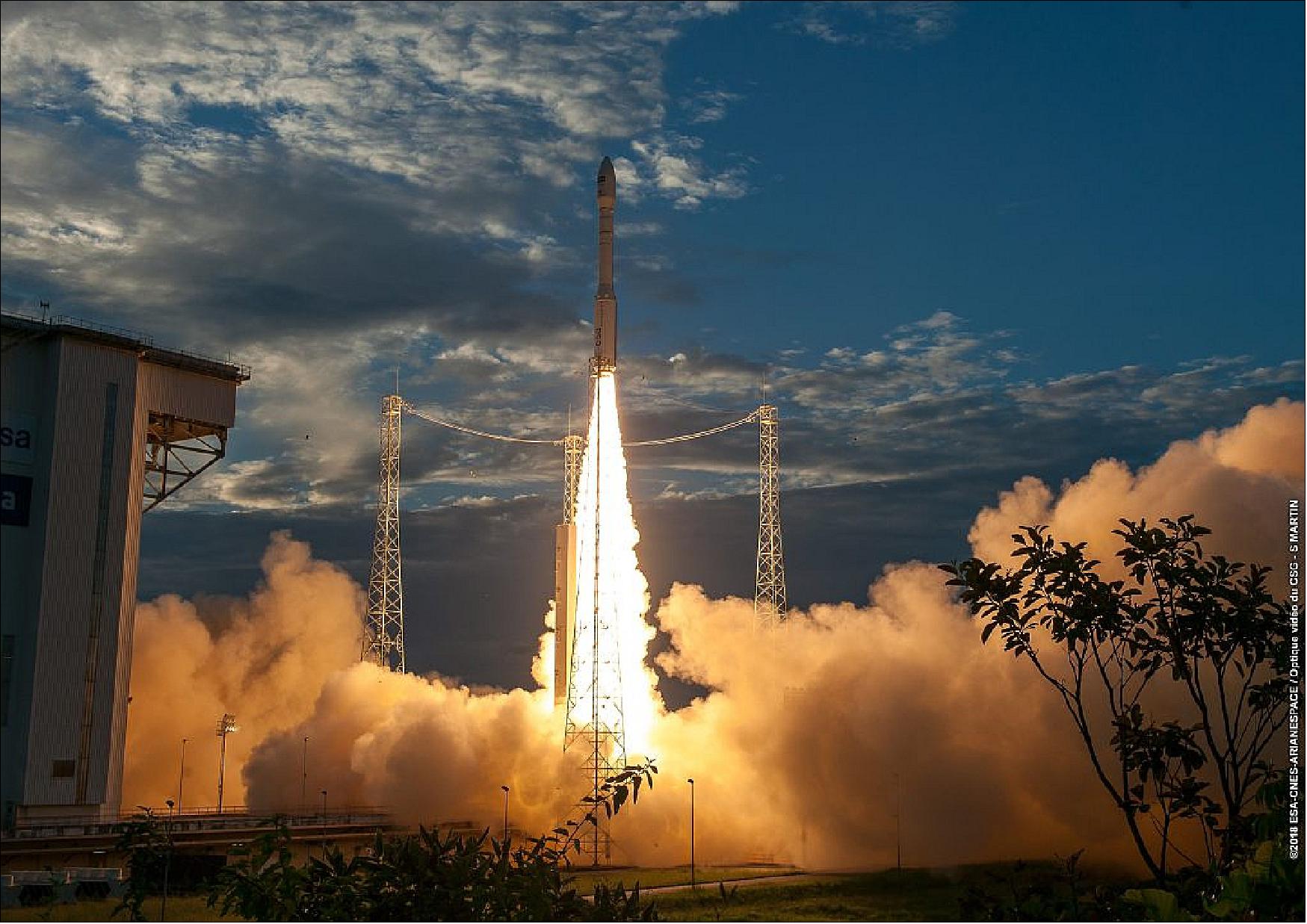
The Aeolus spacecraft was launched on 22 August 2018 (21:20 GMT) on a Vega vehicle, designated VV12, from Kourou, French Guiana. Some 55 minutes later, Vega's upper stage delivered Aeolus into orbit and contact was established through the Troll ground station in Antarctica. The satellite was controlled from ESA's ESOC (European Space Operations Center) in Darmstadt, Germany. Controllers spent the next few months carefully checking and calibrating the mission as part of its commissioning phase. 23) 24) 25)
On September 7, 2016, ESA and Arianespace signed a contract to secure the launch of the Aeolus satellite. With this milestone, a better understanding of Earth's winds was another step closer. With the main technical hurdles resolved and the launch contract in place.
In 2015, a launch of ADM-Aeolus was expected in 2017 (the original launch date was 2007, then in 2011). The launch vehicle was Vega and the launch site was Kourou. 26) 27)
An in-depth review of the ALADIN laser, involving independent laser experts, identified the need to make some substantial modifications to the current design in order to regain adequate performance margins for the three years of in-orbit operation. The most significant modification was a change of the operational principle, from ‘burst' to ‘continuous' mode. A requirement review was completed to define the associated requirements mode.
Stable and complete versions of the end-to-end simulator and ground payload data processing software were available, but they needed to be upgraded to support the new continuous mode of the ALADIN instrument. These significant changes to the instrument design delayed the planned launch date to mid-2013. 28) 29) 30)
Orbit
Sun-synchronous orbit, altitude = 320 km (mean), inclination = 96.97º, local equator crossing time at 18:00 (on ascending node) and at 06:00 hours (dawn-dusk orbit), 7-day repeat cycle (111 orbits).
Mission Status
• July 28, 2023: ESA’s wind mission, Aeolus, reentered Earth’s atmosphere on 28 July at around 21:00 CEST above Antarctica, confirmed by US Space Command.
The reentry comes after a series of complex manoeuvres that lowered Aeolus’ orbit from an altitude of 320 km to just 120 km to reenter the atmosphere and burn up.
These manoeuvres formed the first assisted reentry of its kind, and positioned Aeolus so that any pieces that may not have burned up in the atmosphere would fall within the satellite’s planned Atlantic ground tracks. As no regulations regarding satellite reentry were in place when Aeolus was designed in the late 1990s, this assisted reentry was designed by ESA to improve the safety of the end of life procedure. 106)
• May 8, 2023: Engineers and industry partners have strategically planned the reentry of the Aeolus satellite to minimize the risk of debris falling over land by targeting open ocean waters. Over the next few months, Aeolus will gradually descend from its current altitude of 320 km to 280 km, after which ESA’s mission control will lower it further to 150 km. The satellite is expected to burn up as it reaches approximately 80 km above Earth. The exact reentry date depends on solar activity, but Aeolus is anticipated to disintegrate by the end of August. 105)
• April 18, 2023: ESA announced that on April 30, 2023, all nominal operations of Aeolus, the first mission to observe Earth’s wind profiles on a global scale, will conclude in preparation for a series of end-of-life activities. Despite recent upgrades that maintained the satellite's performance, diminishing fuel reserves and heightened solar activity reqiured the mission to end. Scientists and industry specialists have developed a detailed plan for the satellite's re-enter into Earth's atmosphere. Although Aeolus will cease gathering new operational data after April 30, its existing data will remain accessible for research purposes. 104)
• April 26, 2022: The Aeolus satellite has exceeded its 36-month design life, continuing to deliver valuable wind profile data for global weather forecasting and climate modeling. Utilizing the ALADIN laser, Aeolus measured wind speeds and directions by analyzing Doppler shifts from scattered ultraviolet light, making it the first satellite to provide comprehensive wind profiles. Despite increasing instrument noise, its data remained crucial for numerical weather predictions, with experts at the Aeolus Third Anniversary Conference highlighting its significant impact on weather models. The mission also proved instrumental in tracking real-time events, such as the Hunga Tonga volcanic eruption, demonstrating the satellite's broad utility and ongoing importance.
At the conference in Taormina, Sicily, ESA announced an extension of Aeolus's mission for another year, thanks to a successful switch of the laser. Experts noted that Aeolus's data continued to improve weather forecasts and tracking of atmospheric phenomena, with agencies like the UK Met Office and Météo France integrating its data operationally. The conference also sparked discussions on potential follow-on missions, underscoring Aeolus's scientific, economic, and societal value. ESA's Director of Earth Observation Programmes, Simonetta Cheli, emphasized the growing support for future Doppler wind lidar missions in space, building on the success and critical contributions of Aeolus. 31)
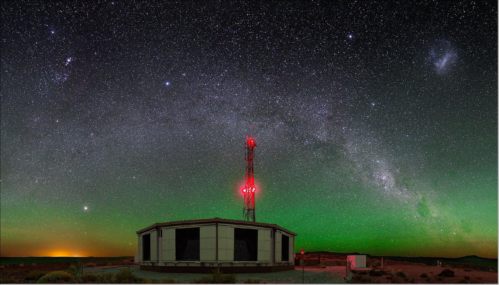
• December 14, 2021: As part of ESA's FutureEO programme, the Aeolus satellite continues to deliver valuable wind data for global weather forecasting and climate research through its advanced Doppler wind lidar technology. The data is rapidly distributed to weather services and fills in the gaps left by reduced aircraft measurements during the COVID-19 pandemic. Beyond meteorology, Aeolus' laser has also contributed to cosmic ray research, aiding in the calibration of cosmic-ray observatories. The mission's success highlights the potential for future Doppler wind lidar satellites and underscores its broader scientific and practical impact. 32)
• September 20, 2021: A team of scientists and technicians from Europe and the US have embarked on an international experiment in the Cabo Verde islands to analyse data from ESA's Aeolus wind mission. The campaign, involving multiple organizations such as ESA, NASA, and the German Aerospace Center, aims to ensure data accuracy, especially in the tropics, by comparing Aeolus' measurements with ground and airborne observations. This collaborative effort also supports upcoming missions like EarthCARE and the development of new concepts like Wivern, despite challenges posed by the COVID-19 pandemic and the recent loss of a key NASA colleague. 34)
• February 4, 2021: As extreme Arctic weather affects parts of the northern hemisphere, scientists are using data from Aeolus to better understand the polar vortex—a massive frigid air mass above the North Pole surrounded by strong winds that can weaken and cause unusual cold weather further south. Recent "sudden stratospheric warming" events, where the polar vortex's boundary winds weaken or reverse and temperatures rise rapidly, have led to dramatic weather changes in North America and Europe. Aeolus has provided crucial insights into these events, helping researchers understand their triggers and the potential impact of climate change on their frequency. 35)
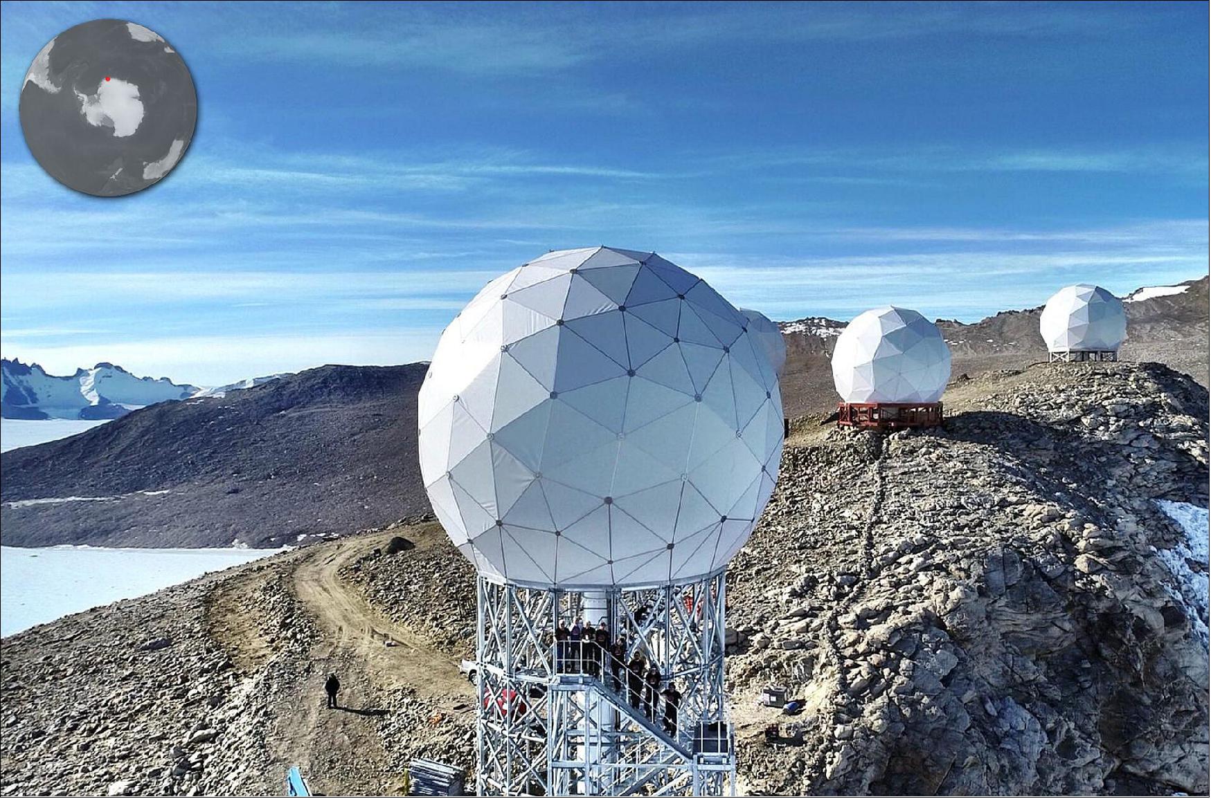
• May 12, 2020: With a new receiving antenna in Antarctica complementing the Svalbard ground station, Aeolus now delivers data to forecasting services and scientists in less than three hours. This near-real-time data distribution has enhanced numerical weather prediction, thanks to data validation and bias correction efforts by relevant experts. The ECMWF has been integrating Aeolus data into their forecasts since January, underscoring the mission's impact on weather prediction and scientific understanding. 36) 37)
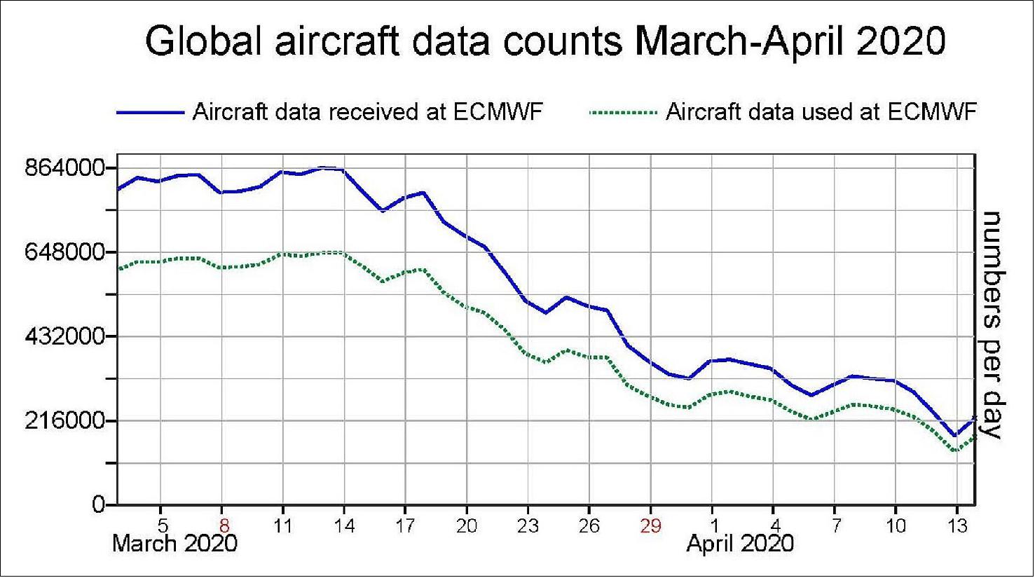
• April 21, 2020: The COVID-19 pandemic has significantly disrupted industries worldwide, notably the travel industry, resulting in a 90% drop in air traffic and a consequent reduction in atmospheric data from commercial aircraft, which are crucial for accurate weather forecasts. Despite this, ESA's Aeolus satellite mission has compensated the data gap, using its laser technology to profile Earth's winds and provide measurements. This has allowed meteorologists to maintain the reliability of weather forecasts during the crisis, with Aeolus data now being used operationally by organizations like ECMWF. Additionally, increased releases of radiosondes are helping to ensure forecast accuracy. 38)
![Figure 26: Impact of aircraft and Aeolus data in ECMWF forecasts before and after the COVID-19-related reduction in air traffic. Forecast Sensitivity to Observation Influence (FSOI) measures how various observing systems influence the ECMWF numerical weather forecast quality. The figure shows the total impact [Mega J/kg] of aircraft data and Aeolus data for two weeks before and after the reduction in aircraft data owing to COVID-19. The impact of Aeolus has increased by 23% (image credit: ECMWF)](https://eoportal.org/ftp/satellite-missions/a/Aeolus_260422/Aeolus_Auto37.jpeg)
• January 10, 2020: ESA's Aeolus satellite has achieved a new milestone as its data is now used by the European Centre for Medium-Range Weather Forecasts (ECMWF) in weather forecasts. This rapid integration is possible thanks to the satellite's novel Doppler wind lidar technology, which emits ultraviolet laser pulses to measure wind shifts. After extensive testing and quality checks, Aeolus has proven to enhance forecasts, particularly in tropical regions and the southern hemisphere. The success of Aeolus not only fills a crucial gap in wind-profile measurements but also sets the stage for future operational Doppler wind lidar satellites. 39)
• November 12, 2019: Aeolus has improved weather forecasts through its innovative wind profile observations using Doppler wind lidar technology. Despite initial biases in its data, collaborative efforts between ESA, ECMWF, DLR, DoRIT, KNMI, and Météo-France have successfully identified and corrected these inconsistencies. Tests conducted at ECMWF demonstrated that integrating Aeolus data into short-range forecasts through data assimilation markedly enhances forecast accuracy, particularly in regions with fewer conventional observations like the southern hemisphere and tropics. This achievement highlights Aeolus's role in advancing meteorological science and lays the groundwork for future missions aimed at refining wind measurements from space. 41)
• October 2019: ESA's Aeolus satellite has achieved significant milestones since its launch with the primary mission of demonstrating the Doppler Wind Lidar (DWL) technology for global wind profile measurements from space. Aeolus provides Horizontal Line-Of-Sight (HLOS) wind profiles spanning from the Earth's surface up to 30 km altitude. The satellite's Level 2A products also include detailed profiles of cloud and aerosol optical properties, enhancing atmospheric research and climate modeling evaluations. Despite encountering initial challenges such as fluctuations in laser energy and "hot" pixels affecting data quality, Aeolus implemented effective in-orbit corrections to maintain data integrity. The satellite's operational readiness was confirmed with the release of its first public wind data in Q1 2020, facilitating its assimilation into Numerical Weather Prediction (NWP) models and demonstrating significant positive impacts, particularly in regions with sparse wind observations like the tropical troposphere and southern hemisphere. 42)
Throughout its mission, Aeolus has provided consistent and reliable wind observations, fulfilling stringent precision and bias requirements across various atmospheric layers. Its integration into NWP models worldwide has shown substantial improvements in forecast accuracy, validating the effectiveness of DWL technology for operational meteorological applications. Lessons learned from Aeolus, including the need for robust optical coatings to prevent laser-induced contamination and improvements in telemetry acquisition rates for future missions, underscore its role in advancing satellite-based atmospheric monitoring capabilities. As efforts continue to optimize instrument calibration and data processing, Aeolus remains a cornerstone in global efforts to enhance weather forecasting and deepen understanding of atmospheric dynamics.
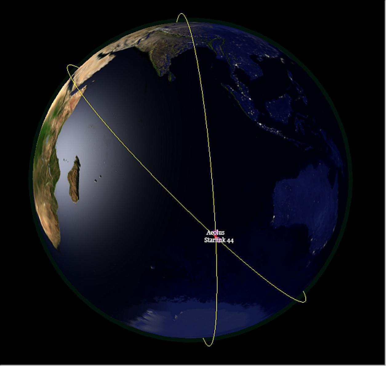
• September 3, 2019: ESA conducted its first-ever collision avoidance maneuver to protect the Aeolus satellite from a potential collision with a Starlink satellite from SpaceX's constellation. As the number of satellites in orbit increases, such close approaches will become more frequent, requiring automated systems for collision avoidance. ESA's maneuver, triggered by a calculated collision probability exceeding 1 in 10,000, involved raising Aeolus' altitude to safely pass over the other satellite. Despite initial challenges in coordinating with Starlink, the maneuver was successfully executed, affirming the need for enhanced space traffic management and automated protocols to ensure the sustainability and safety of Earth's orbital environment amidst the burgeoning satellite constellations. 43)
• July 23, 2019: ESA's Aeolus satellite has successfully transitioned to its second laser after the first began to lose energy. This switch has restored the mission's ability to provide high-quality wind data crucial for meteorological forecasts and scientific research. Despite the initial challenge with declining laser energy, Aeolus accumulated significant data with its first laser, setting a record for space-based ultraviolet lasers. Now, with the second laser operational and showing stable energy levels, the mission is poised to continue delivering insights into global wind patterns and their impact on weather forecasting and climate studies. 44)
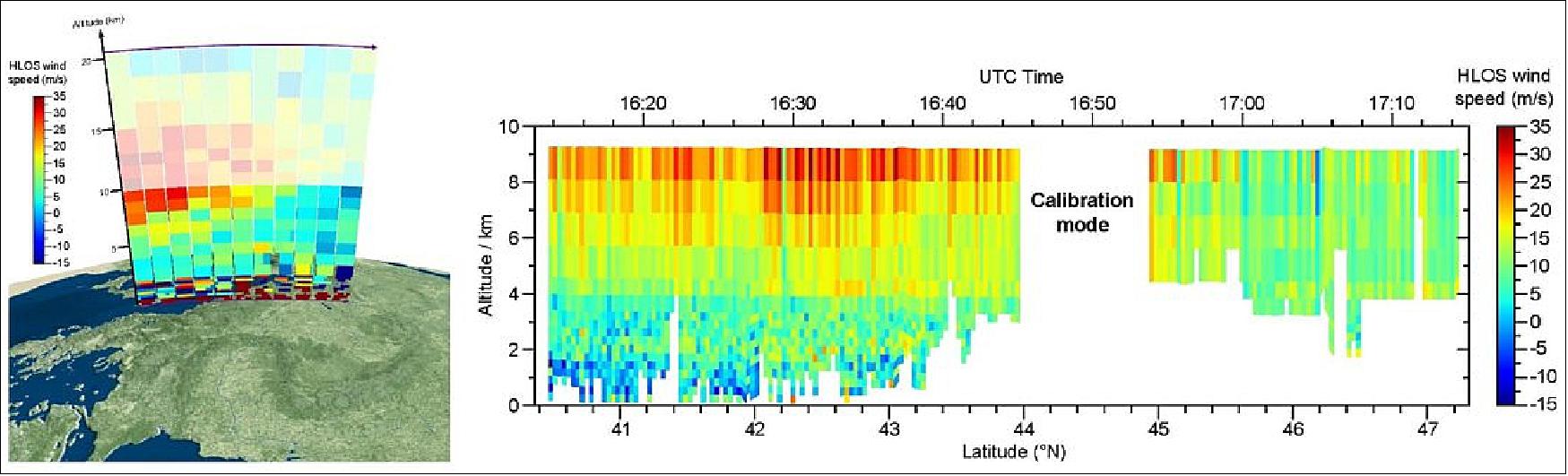
• April 5, 2019: Engineers and scientists have dedicated significant effort over the past months to assess and validate the accuracy of wind data collected by the Aeolus satellite, equipped with pioneering laser technology. After thorough calibration against ground, aircraft, and satellite measurements, preliminary analyses from ECMWF and DWD indicate that Aeolus winds are already improving forecasts, particularly in the troposphere. These findings were presented at a recent workshop gathering international experts. 45)
• February 11, 2019: Since its launch, Aeolus has undergone rigorous assessment to validate its ability to measure global wind patterns from space. Engineers and scientists have been comparing the satellite's data with modelled forecasts from ECMWF, noting significant improvements in forecast accuracy. As Aeolus transitions from its commissioning phase, efforts are focused on refining data processing methods tailored to its unique instrumentation. Field campaigns worldwide, including a recent effort by DLR in Germany, further contribute to calibration and validation efforts, ensuring that Aeolus delivers reliable wind measurements crucial for advancing meteorological predictions. 46) 47)
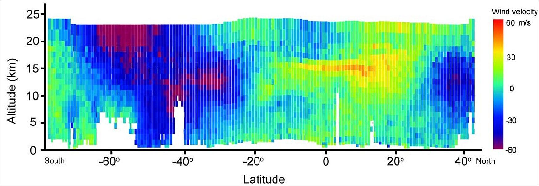
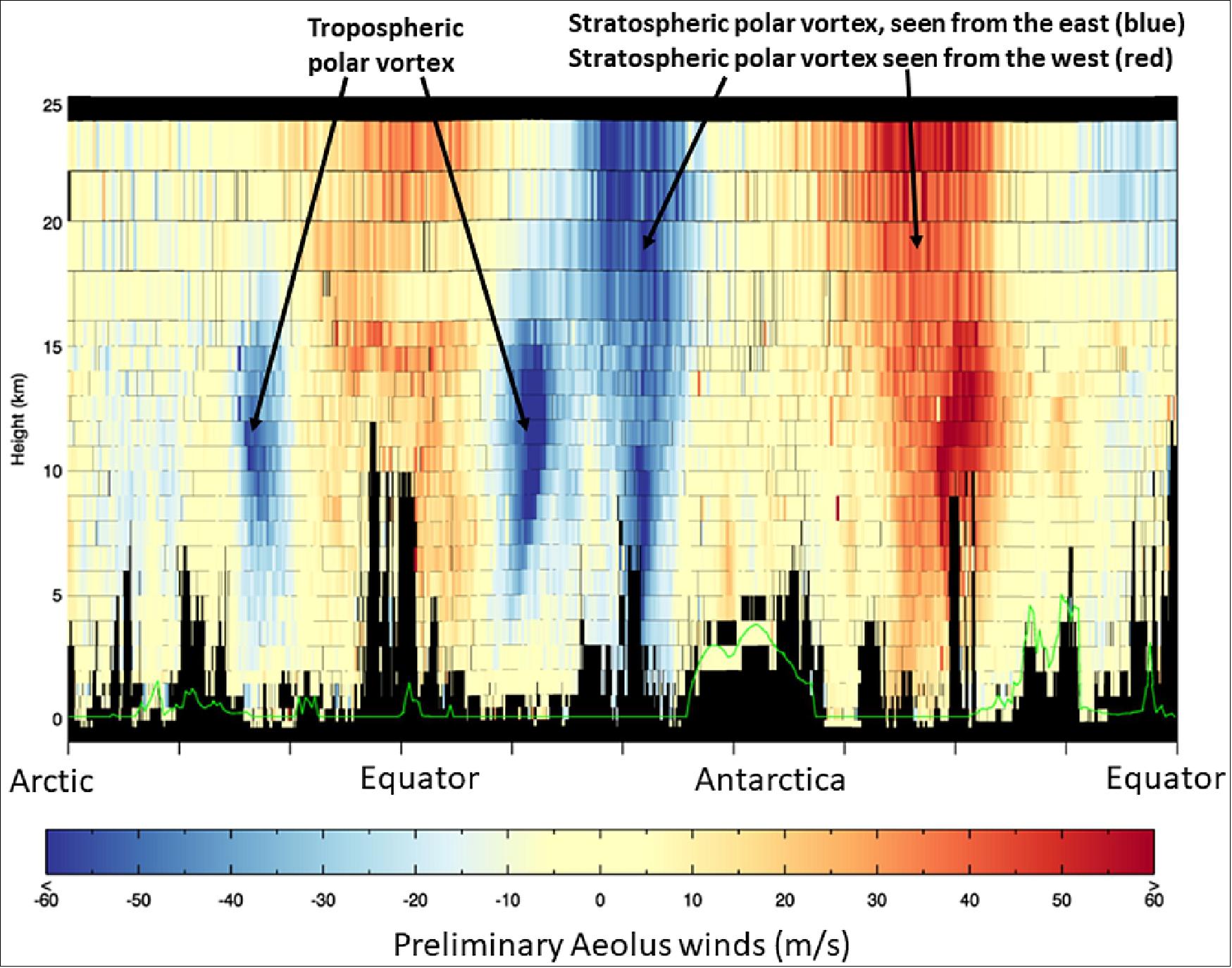
• September 12, 2018: Aeolus has proven its capability by delivering high-quality wind data within just weeks of its launch. Aeolus has already exceeded expectations by providing detailed wind profiles from Earth's surface to the lower stratosphere, including significant features like jet streams and the Stratospheric Polar Vortex. 48)
• September 5, 2018: ESA's Aeolus satellite has successfully activated its ALADIN instrument, marking a significant milestone in its mission to measure Earth's wind patterns using revolutionary laser technology. This phase of commissioning, expected to last approximately three months, commenced with the critical task of verifying the laser's functionality. According to ESA officials and partners like Airbus Defence and Space, Aeolus has already surpassed expectations by providing initial wind data within days of activation. This achievement underscores the mission's importance in addressing global meteorological data gaps and its potential to enhance weather forecasting and climate research once fully operational. 49)
• August 24, 2018: Following its successful separation from the Vega launcher, Aeolus established communication with ground stations in Australia and Antarctica, confirming operational status. Flight controllers at ESOC are now guiding Aeolus through its commissioning phase, aimed at optimizing its orbit and thoroughly testing onboard systems. The primary objective during this phase is to verify and calibrate the ALADIN instrument, laying the groundwork for precise wind measurements crucial for enhancing meteorological forecasts and advancing climate research. 50)
The DWL (Doppler Wind Lidar) Operation Principle of ALADIN
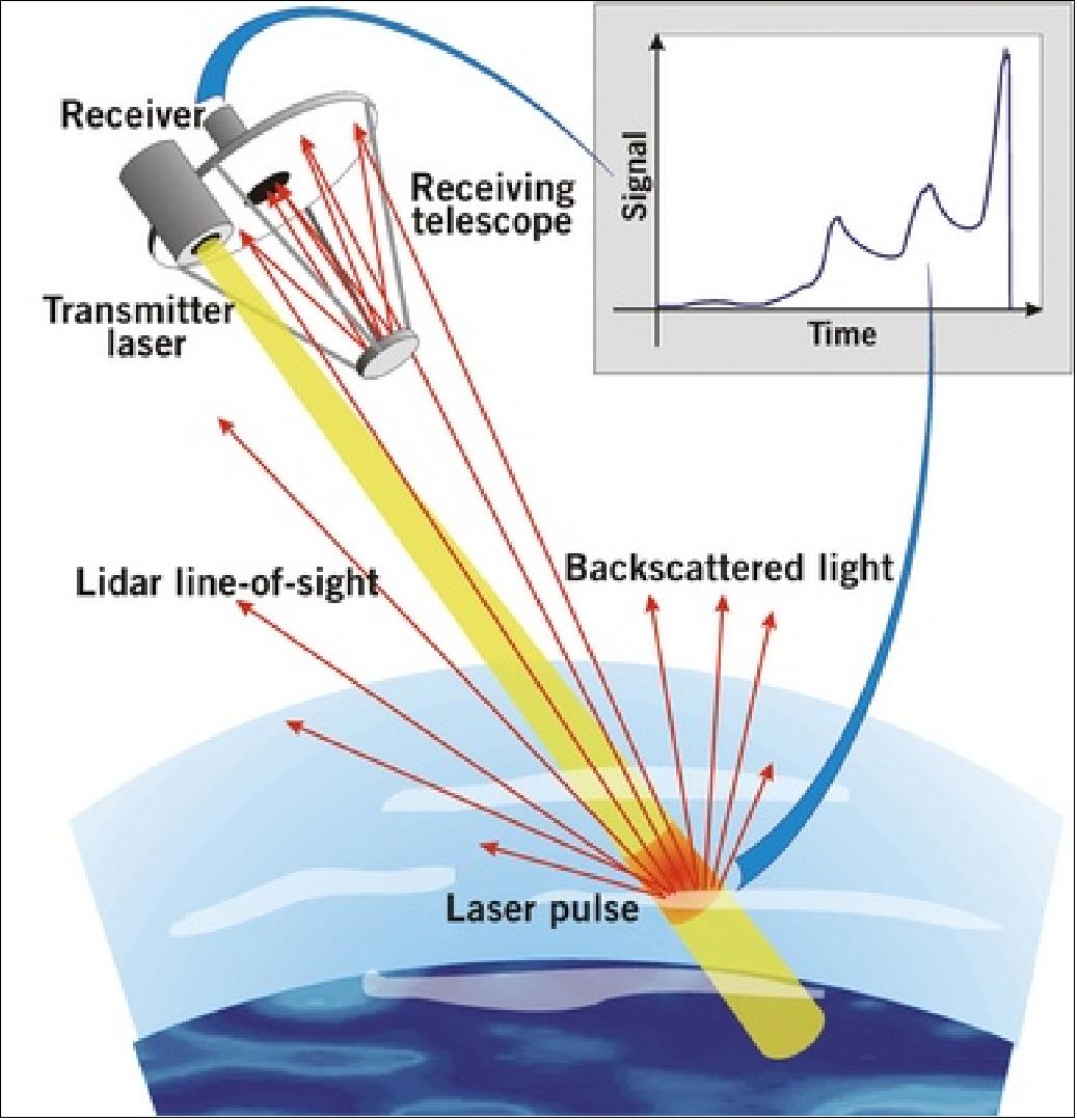
DWL is an active observation technique; the instrument fires laser pulses towards the atmosphere and measures the resulting Doppler shift of the return signal, backscattered at different levels in the atmosphere. The frequency shift results from the relative motion of the scatter elements along the sensor line of sight. This motion relates to the mean wind in the observed volume (cell). The measurement volume is determined by the ground integration length of 50 km (sample size), the required height resolution and the width of the laser footprint. The measurements are repeated at intervals of 200 km.
Light is scattered either by interaction with aerosol or cloud particles (Mie scattering) or by interaction with air molecules (Rayleigh scattering). The two scattering mechanisms exhibited different spectral properties and different wavelength dependencies such that instruments evaluating only one signal type or both in separate processing chains can be constructed.
To improve the detection of the Rayleigh signal, the laser emits light pulses in the UV spectral region (355 nm). Detection of the backscatter light and analysis of the Doppler shift is done with high-resolution spectrometers (about 5 x 10⁸ resolving power).
For lidar techniques where the shape of the backscattered light couldn't be directly measured in detail, it was important to know what shape was expected in order to calculate the speed, abundance, temperature or chemical composition of molecules in the atmosphere. - The shape of the backscattered light was described by ‘Rayleigh-Brillouin scattering theory', where the Rayleigh scattering was related to the temperature and Brillouin scattering was related to pressure fluctuations in the atmosphere. The shape of the Rayleigh-Brillouin backscattered light was described by the ‘Tenti' model, which was created in the early 1970s. This model was used worldwide to interpret atmospheric lidar measurements. 51)
Although early ESA studies showed this model to be suitable for interpreting data from the Agency's satellites carrying lidars, it was decided to launch a new laboratory experiment, through ESA's General Studies Program, to see if there was still room for improvement. An advanced model would have led to even better accuracy in lidar measurements.
The study was led by Wim Ubachs of the Laser Centre at the VU University Amsterdam in the Netherlands. The team included participants from the VU University Amsterdam, the University of Nijmegen, Eindhoven University of Technology, the KNMI (Royal Netherlands Meteorological Institute) and the German Aerospace Center, DLR. 52)
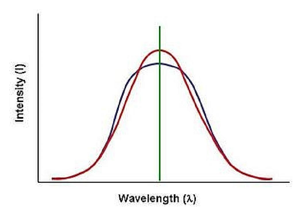
Measurements of Rayleigh-Brillouin scattering were taken for a range of pressures and gases, representative of Earth's atmosphere. The measurements were compared to the Tenti model, and as a result the model could be improved. The experiment concluded that the updated Tenti model described the shape of the backscattered light from nitrogen and oxygen to within an accuracy of 98%. It was also confirmed that atmospheric water vapor did not affect the Rayleigh-Brillouin line shape. In addition, the scattering profiles from nitrogen, oxygen and air were shown to be the most accurate ever measured worldwide and will now form the basis for further scientific research into Rayleigh-Brillouin scattering.
The study has delivered a wide variety of profiles that are important, not only to ESA's lidar missions, but also to other scientists working with lidar instruments. Some important issues dealing with the understanding of the profiles related to wavelength, scattering angle and temperature dependencies and polarization effects are still open and will be further studied in a follow-on activity with ESA.
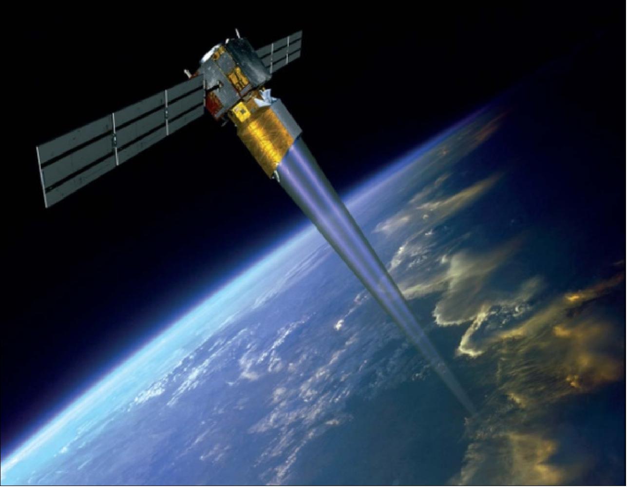
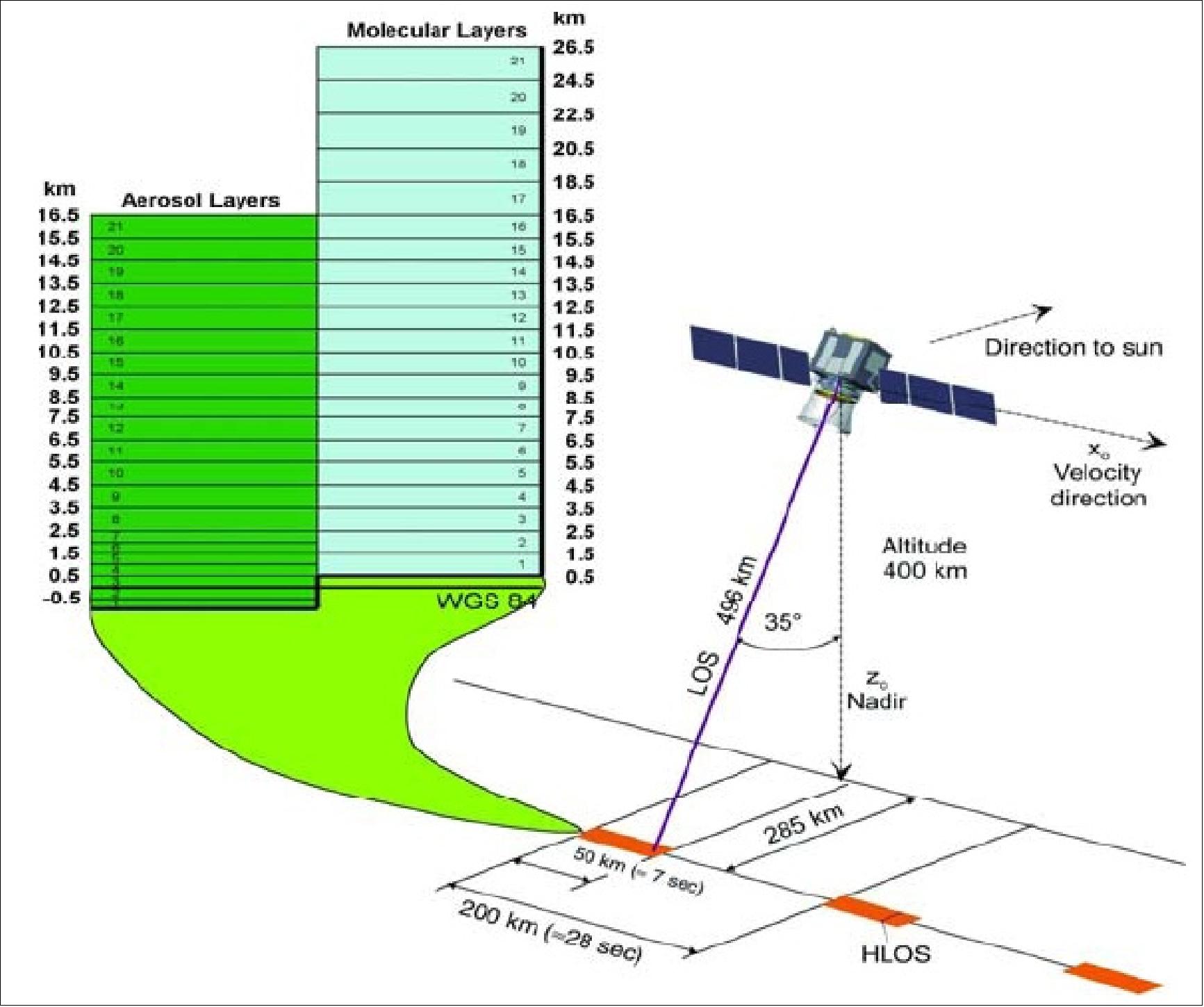
Observation Configuration
The satellite is flown with the ALADIN instrument pointing toward Earth in a plane quasi-perpendicular to the flight path and 35º offset from nadir in the anti-sun direction. The LOS was oriented such that the relative velocity at the intersection with the Earth is zero (yaw steering). All measurements were taken along the LOS. The Doppler shift of the backscatter signal reflects the relative wind speed along the LOS and has to be processed to a horizontal wind speed component, HLOS (Horizontal Line-of-Sight), referenced to the ground.
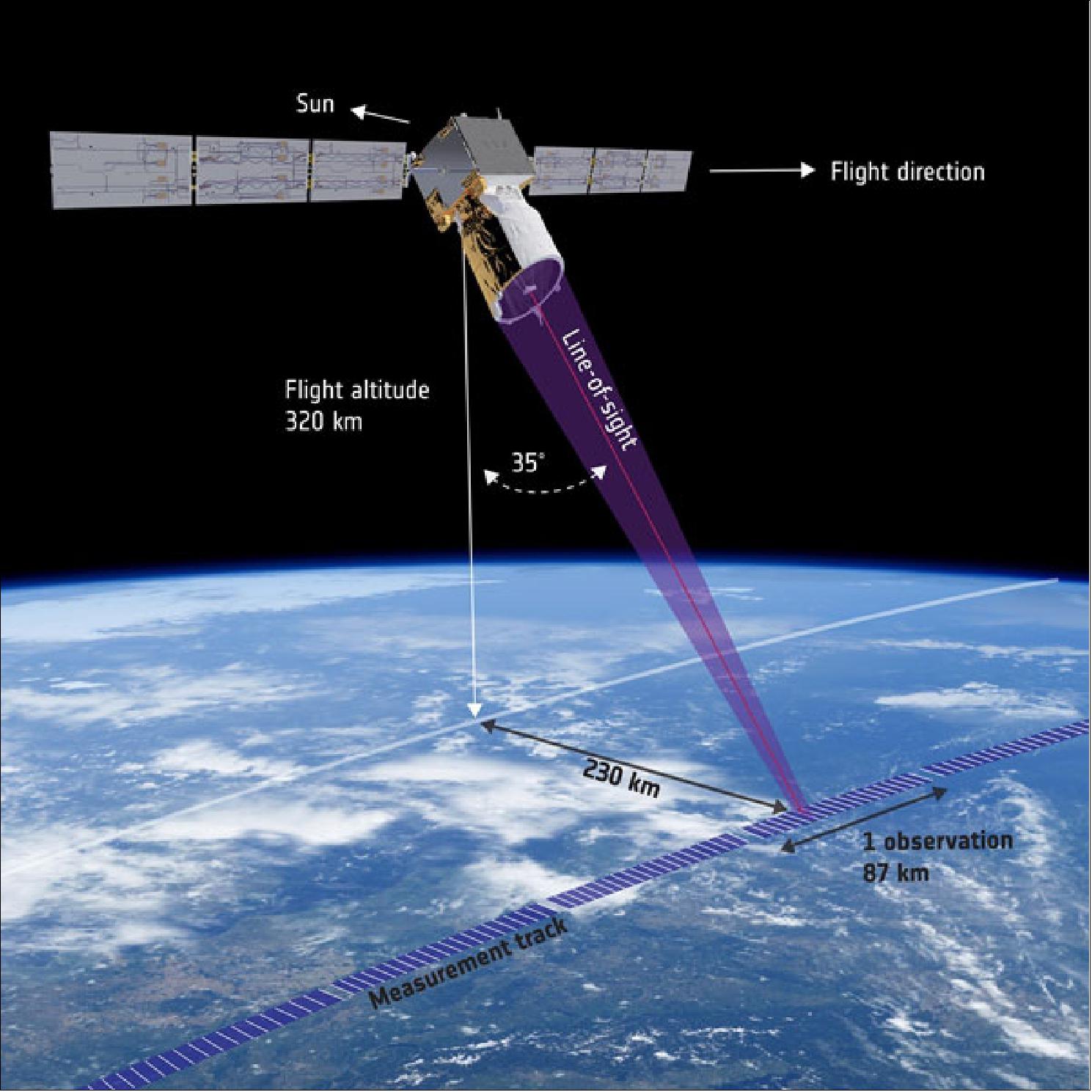
The measurement volume of the return signal from a single shot was defined by the lateral extension of the transmitted beam (a few meters in diameter) and the time gating of the receiver, which is adapted to the desired vertical resolution (250 m to 2 km or more). Due to the fact that the signal from a single shot was too weak for the evaluation, 700 shots along a ground measurement track of 87 km have to be accumulated and integrated.
Measurement profile: The onboard instrument is operated at a duty cycle of 25% to obtain wind profile separation. An active operation cycle lasts 7 seconds (equivalent to about 87 km ground track), followed by a gap in observations of 21 seconds (equivalent of nearly 150 km ground track). Winds can be measured in clear air (i.e., above or in the absence of thick clouds), and within and through thin clouds (e.g., cirrus).
Sensor Complement
ALADIN (Atmospheric Laser Doppler Instrument)
The instrument was developed by Airbus DS (former EADS Astrium SAS), Toulouse, France as prime contractor of an industrial consortium.
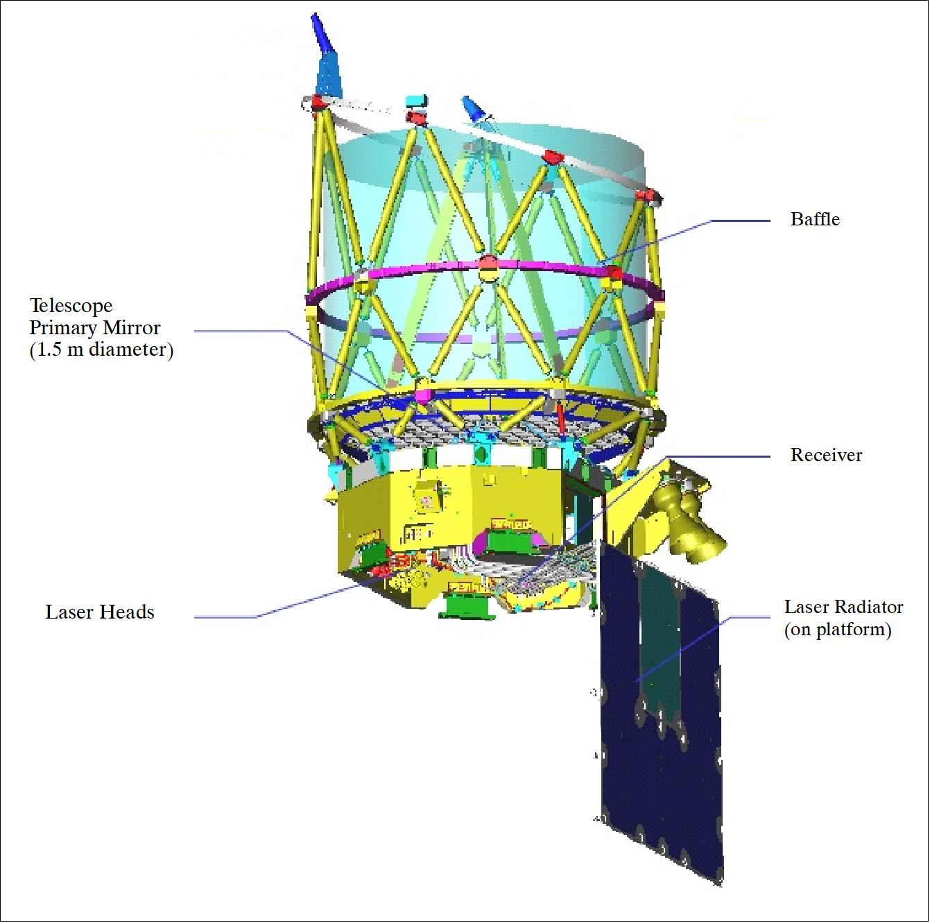
ALADIN was an incoherent direct detection lidar incorporating a fringe-imaging receiver (analyzing aerosol and cloud backscatter) and a double-edge receiver (analyzing molecular backscatter). The lidar emitted laser pulses towards the atmosphere, then acquired, samples, and retrieved the frequency of the backscattered signal.
The overall ALADIN instrument architecture was based on a 60 mJ diode-pumped frequency-tripled Nd:YAG laser operating in the ultraviolet (solid-state laser technology). The instrument consisted of three major elements: a transmitter, a combined Mie and Rayleigh backscattering receiver assembly, and the opto-mechanical subsystem (a telescope with a 1.5 diameter). After integration, the telescope wavefront error was measured within the specification (better than half a wavelength). This was a key parameter for minimizing the bias error on the wind speed. 53) 54) 55) 56) 57) 58) 59) 60) 61) 62) 63) 64) 65) 66) 67) 68)
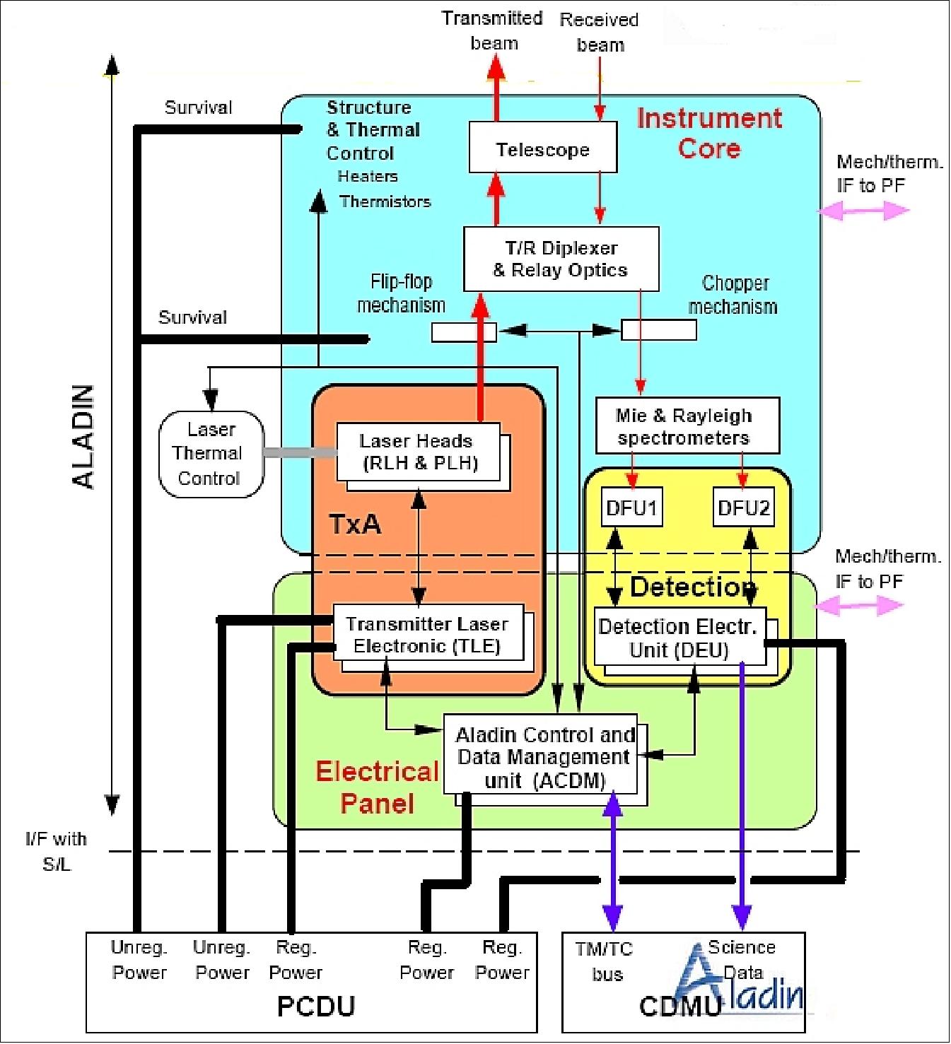
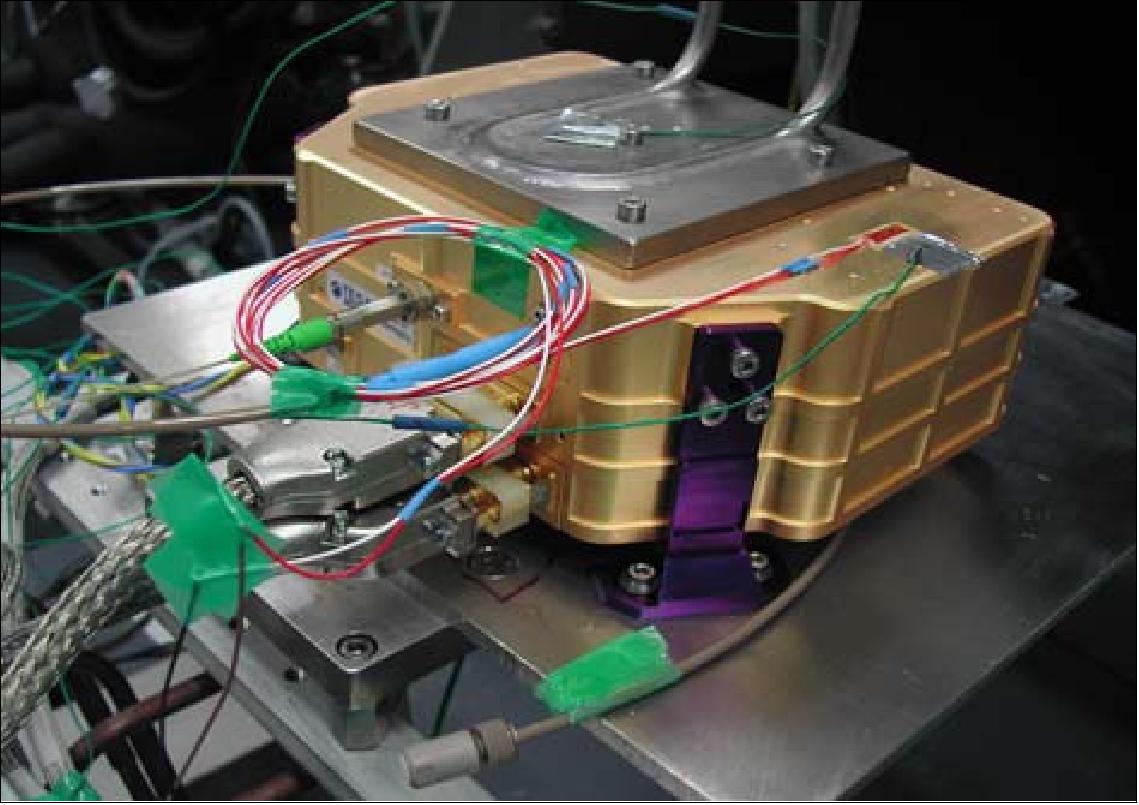
TxA (Transmitter Laser Assembly). The transmitter laser is a diode pumped solid state laser (Nd:YAG). The TxA was composed of:
• PLH (Power Laser Head)
- Diode-pumped Nd-YAG laser
- Emits 60 mJ pulses @355 nm
- Pulse repetition frequency of 100 Hz
- 12 s “bursts” every 28 s
• RLH (Reference Laser Head) 69)
- Highly stable seed laser (a few MHz)
- Tunable over 7 GHz
• PLH and RLH are being conductively cooled
• TLE (Transmitter Laser Electronics)
- High current and voltage driver
- Transmitter control and synchronization.
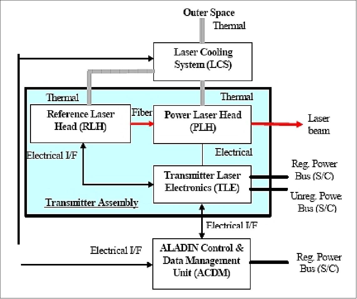
The power laser was composed of a low power oscillator (10 mJ output energy) and two power amplifiers to generate light pulses with 150 mJ energy at the fundamental wavelength of Nd:YAG (1064 nm). This was converted to 60 mJ pulses in the UV (355 nm) by a frequency tripler. The oscillator was actively Q-switched by a Pockels cell. A seed laser was used as frequency reference. The injection seeding technique was used to achieve a single frequency mode with a low-power continuous wave (CW) single frequency laser. The power laser was conductively cooled via heat pipes. The transmitter assembly will be operated in burst mode with 100 Hz PRF during 7 seconds (plus a 5 second warm-up time), in intervals of 28 seconds. There were two fully redundant transmitters, each including two laser heads (Power Laser Head and Reference Laser Head), and a TLE (Transmitter Laser Electronics) module.
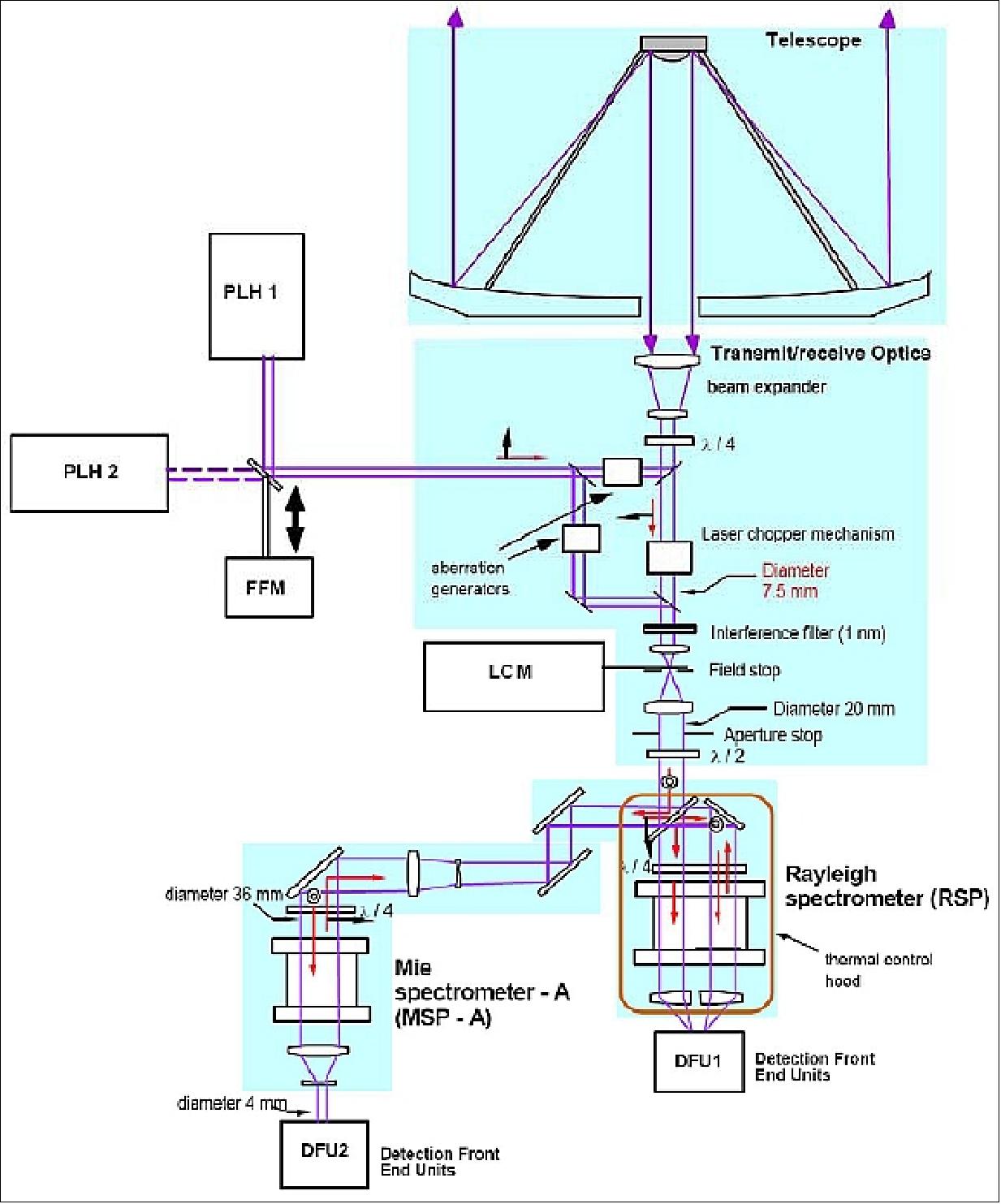
Receiver assembly: A combined Mie and Rayleigh backscattering receiver was implemented. The receiver assembly included the transmit/receive switch (polarization-based), a set of relay optics and diplexers for beam transport and laser reference calibration, a blocking interference filter, the Mie and Rayleigh receivers (spectrometers), and two DFU (Detection Frontend Units).
• The Mie receiver consisted of a Fizeau spectrometer. The received backscatter signal produced a linear fringe whose position was directly linked to the wind velocity. The resolution of the Fizeau interferometer was 100 MHz (equivalent to 18 m/s). The wind value was determined by the fringe centroid position to better than a tenth of the resolution. The backscattered signals were detected by a thinned back-illuminated silicon CCD detector working in an accumulation mode which allowed photon counting. In the Mie channel, the Doppler shift was estimated by measuring the displacement of straight fringes produced by either a Fizeau or a two-wave interferometer.
• The Raleigh receiver employed a dual-filter (also referred to as double-edge) Fabry-Perot interferometer (where the Doppler shift was estimated from the variation of the signal transmitted through two filters located on both sides of the broad Rayleigh spectrum) with a 2 GHz resolution and 5 GHz spacing. It analyzed the wings of the Rayleigh spectrum with a CCD. The etalon was split into two zones, which were imaged separately on the detector. The wind velocity was proportional to the relative difference between the intensities of the two etalons.
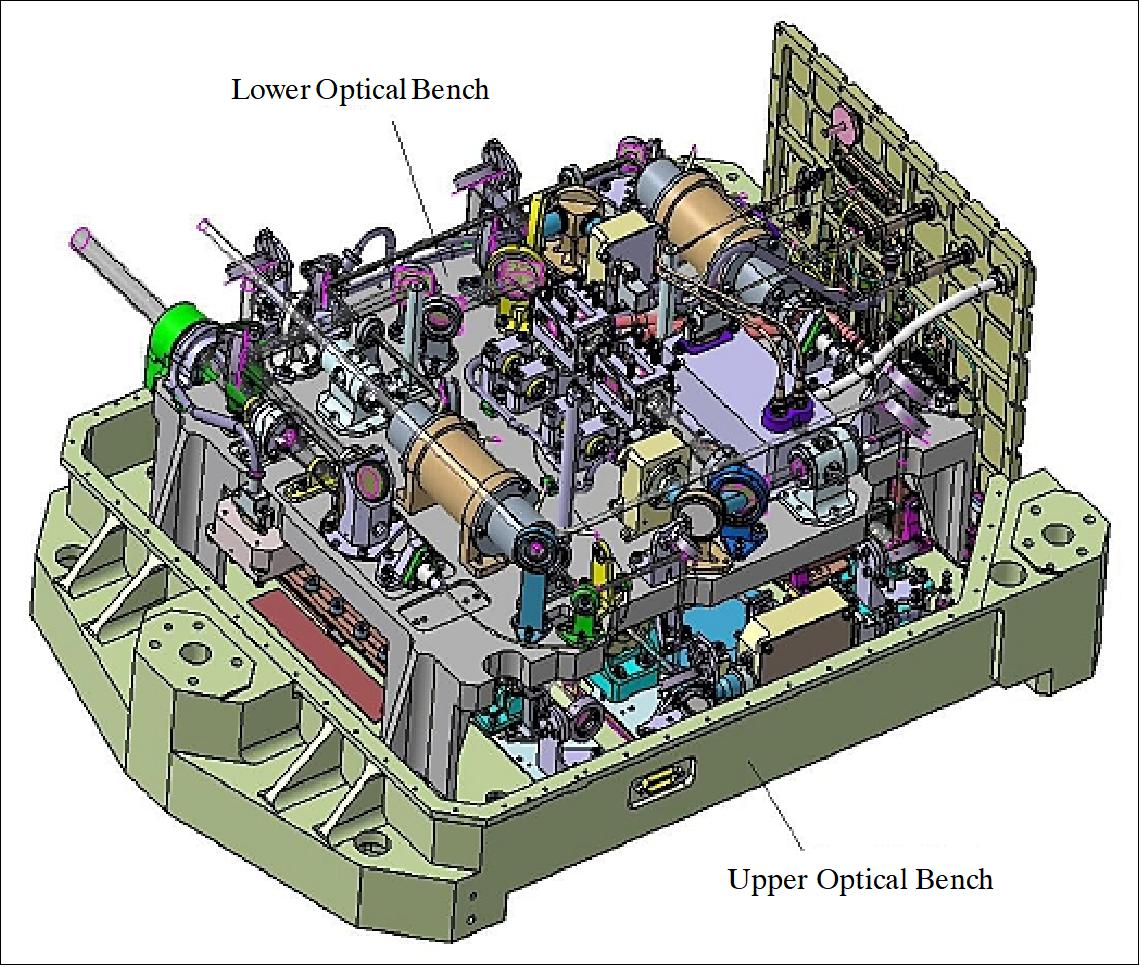
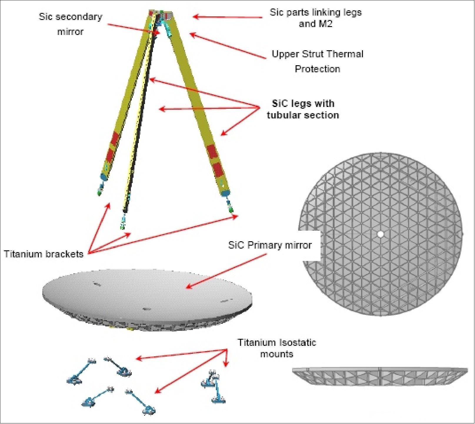
The optomechanical subsystem of ALADIN used a Cassegrain afocal telescope for both functions of laser emission and backscatter reception. The optomechanical architecture employd the monostatic observation concept: i.e., the transmit and receive beams propagated through the same telescope.
This architecture allowed to limit the instrument FOV: to ameliorate for instance the daytime performance, and to relax the telescope and optics stability requirements. TRO (Transmit-Receive Optics) was a major subsystem of ALADIN, directing the laser pulses towards the atmosphere, generating internal reference signals and feeding the atmospheric return signal into the subsequent optical analyzers. 70)
The telescope design employed isothermal and lightweight techniques based on SiC (Silicon Carbide) type ceramic mirrors and structures. This concept provided the needed optical quality and stability without a focusing or alignment mechanism. Star trackers for attitude sensing were mounted on the telescope structure to minimize the misalignment between the optical axis and the telescope's line-of-sight.
The instrument transmitted raw source data consisting of the accumulated spectra from the Mie receiver and the flux intensities from the Rayleigh receiver. These data were provided for strips of 50 km length and a horizontal resolution down to 3.5 km. In the vertical direction, many layers or volume cells of the various altitude bins (nominally -1 km to 16.5 km height for the Mie channel, and 0.5 km to 26.5 km for the Rayleigh channel, but other scenarios can be uplinked in flight) were measured; the instrument looks into a fixed direction (quasi perpendicular to the flight path and 35º away from nadir) and provided a vertical wind profile along the line of sight.
In addition to these source data, laser internal calibration and attitude data were transmitted, as well as the receiver response calibration data.
The instrument performance considered the SNR error for each channel at the indicated altitude range. In addition, systematic bias errors were taken into account. When no ground echo was retrieved, the measurement bias was not cancelled; the total measurement error was slightly deteriorated. - For the Mie channel, the LOS (Line-of-Sight) wind error was below the requirement of 0.6 m/s for altitudes from 0 to 2 km in height. For the Rayleigh channel, the LOS wind error was below the requirement (except a marginal performance around 16 km).
| Aeolus requirements | Aeolus predicted performances | ||||
Parameter | Planetary Boundary Layer (PBL) | Troposphere | Stratosphere | PBL | Troposphere | Stratosphere |
Wind velocity range |
| ±150 m/s | ||||
Vertical domain | 0-2 km | 2-16 km | 16-20 km | 0 - 2 km | 2 - 16.5 km | 16.5-26.5 km |
Vertical resolution | 0.5 km | 1.0 km | 2.0 km | 0.25 km | 1.0 km | 2.0 km |
Horizontal domain | global coverage | 80º S to 85º N | ||||
Number of profiles/hour | 100 | 100 | ||||
Profile separation | > 200 km | > 200 km | ||||
Temporal sampling | 12 hours | 12 hours | ||||
Accuracy of wind velocity | 2 m/s | 2-3 m/s | 3 m/s | < 1 m/s | < 2 m/s | 2 m/s |
Horizontal integration | 50 km | 50 km | ||||
Bias error | 0.4 m/s | 0.35 m/s | ||||
Slope error | 0.7% | 0.7% | ||||
Reliability | 95% | > 95% | ||||
Timeliness of data availability | 3 hours | > 3 hours | ||||
Length of observational data set | 3 years | 3 years | ||||
Instrument type | Diode-pumped Nd:YAG lidar with active Q-switch |
Transmitter (emitter) |
|
Receiver |
|
Signal processing capabilities |
|
Opto-mechanical subsystem |
|
Instrument mass, power | 500 kg, 840 W average power (25% duty cycle) |
Instrument data rate | 11 kbit/s (max) |
Technology Introduction
The ALADIN instrument on ADM-Aeolus employed several novel technologies, like:
- Fizeau interferometer for aerosol return
- Sequential Fabry-Perot interferometer for molecular return
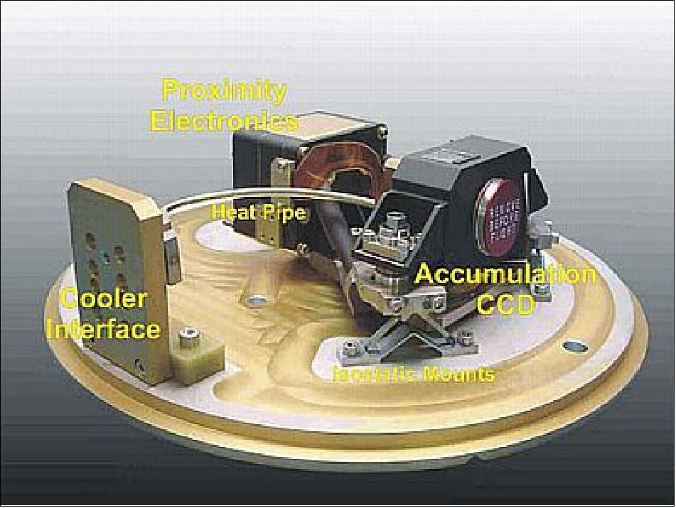
- Accumulation CCD as detector (also referred to as ACCD).
Parameter | PBL (Planetary Boundary Layer) | Troposphere | Stratosphere |
Vertical domain | 0-2 km | 2-16 km | 16-20 km (30) |
Vertical resolution | 0.5 km | 1.0 km | 2.0 km |
Horizontal domain | global | ||
No of profiles | > 100 /hour | ||
Profile separation | > 200 km | ||
Horizontal integration length | 50 km | ||
Horizontal sub-sample length | 0.7 to 50 km | ||
Accuracy (HLOS component) | 1 m/s | 2 m/s | 3 m/s (5) |
Data reliability | 95% | ||
Data availability | 3 hours (0.5) | ||
Length of observational data set | 3 years | ||
A programmable sequencer was implemented for the detector permitting configuration changes with regard to vertical altitude resolution and range coverage. The vertical resolution could vary from 250 m to 2 km or more. However, the measurement accuracy was only obtained for the nominal vertical resolution of 1 km. The altitude range was limited to 30 km. The horizontal (along-track) onboard accumulation length could also be changed between a distance of 1.0 km and 3.5 km.
In addition to the horizontal line-of-sight (HLOS) velocity measurements, ALADIN was able to provide information on cloud characteristics over the depth of the atmosphere, as well as aerosol measurements in the troposphere. These included:
• Cloud top height (notably cirrus top and base)
• Cloud cover
• Cloud and aerosol extinction and optical thickness
• Identification of multi-layer clouds
• Lower troposphere aerosol stratification
• The height of the tropopause
• The height of the PBL (Planetary Boundary Layer).
Change of operational principle (change from burst mode to continuous mode for ALADIN laser):
The change of operational principle of the laser transmitter had minor impact on the other sub-systems of ALADIN and on the platform. Exchange of FPGA (Field Programmable Gate Arrays) in the TLE (Transmitter Laser Electronics), the DEU (Detection Electronics Units) and the ALADIN Control & Data Management unit (ACDM) as well as minor modifications of the operation software and the ground processing software are required (Ref. 67).
The laser transmitter continued to be the greatest development challenge. Delays in the transmitter program resulted from two main problem areas, namely LIC (Laser-Induced Contamination) caused by the interaction of the high power UV beam with outgassing materials in the vicinity of optics, and LID (Laser-Induced Damage) due to the fact that some of the optics are near the “state of the art” in terms of surviving the high fluences of the laser, particularly in the UV section. 71)
One of the most extensive test programs for LID was undertaken by DLR Stuttgart, on each of the coating lots of all flight optics, along with a number of endurance tests, in order to demonstrate sufficient LIDT margins for the duration of the mission.
The first flight model of ALADIN laser had been integrated and the second flight model integration was prepared. Once the lasers were fully characterized and delivered, the integration of ALADIN resumed.
Ground Segment
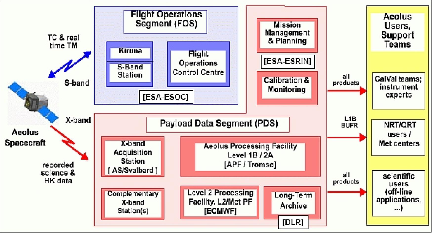
Spacecraft operations were performed at ESOC (Darmstadt, Germany) using the Kiruna TT&C station. The instrument data was received nominally by the ground station in Svalbard (Spitzbergen). Additional X-band receiving stations (antenna diameter as small as 2.4 m) could easily be added to provide a shorter data delivery time.
The two primary components of the Ground Segment were the FOS (Flight Operations Segment) and the PDS (Payload Data Segment). The Aeolus ground segment at ESOC was scheduled to use the latest version of the SCOS-2000 mission control system (version 5).
For the complete mission duration (launch up to the end of mission, when ground contact to the spacecraft/payload was terminated), facilities and services were provided to the PDS (Payload Data Segment) located at ESA/ESRIN (Frascati, Italy) for planning of scientific data acquisition. This included the uplink of instrument operation timelines as well as the provision of scientific data downlink schedules based on the predicted spacecraft orbit. The PDS was responsible for measurement data acquisition via the X-band station network, the preprocessing of scientific data, and the scientific data archiving and distribution to the Meteorological Centers and general scientific community. 72) 73)
The FOCC (Flight Operations Control Center) operated from a dedicated control room at ESOC. Data processing was done at ESA/ESRIN, while wind profile retrieval was done by the ECMWF (European Centre for Medium-Range Weather Forecasts), UK. Data ground processing would have been completed within five minutes after reception. 74)
The key operational requirements for Aeolus driving the overall mission operations concepts were:
• Aeolus should have returned near global measurements of wind speed
• Data measurements should have been collected with an availability of 0.95
• The collected data should have been delivered to the Data Center in less than three hours from the time of measurement
• Full 5 day autonomy including a sustainable safe mode
• Orbit related driven specifications for repeat periods, orbit period, pattern of ground station passes, and frequency of orbit control maneuvers.
Operational automation in the ground segment: ADM-Aeolus opted to be one of the first missions to utilize the mission automation systems developed as part of ESOC infrastructure, namely MATIS (Mission Automation System) and SMF (Services Management Framework). An initial simple automation approach had been taken to allow Aeolus to set automation targets which would have had no impact on FOCC readiness for flight. Two simple initial targets had been set:
- Automation of Control Center to TT&C station link configuration pre-pass and post-pass
- Automation of playback of the X-band HK data dumps.
A further automation phase would have covered TM monitoring, analysis and reporting.
The PDS would have been in charge of the science data reception via X-band and of various processing, archiving and product dissemination tasks. It would have included the X-band acquisition station located in Svalbard (Norway), the APF (Aeolus Processing Facility ) located in Tromsø (Norway) for the processing and dissemination of the Level 1B and Level 2A products, and the Level 2 Processing Facility (L2/Met PF) hosted by the ECMWF (European Centre for Medium Range Weather Forecast) in Reading (UK).
Data Products
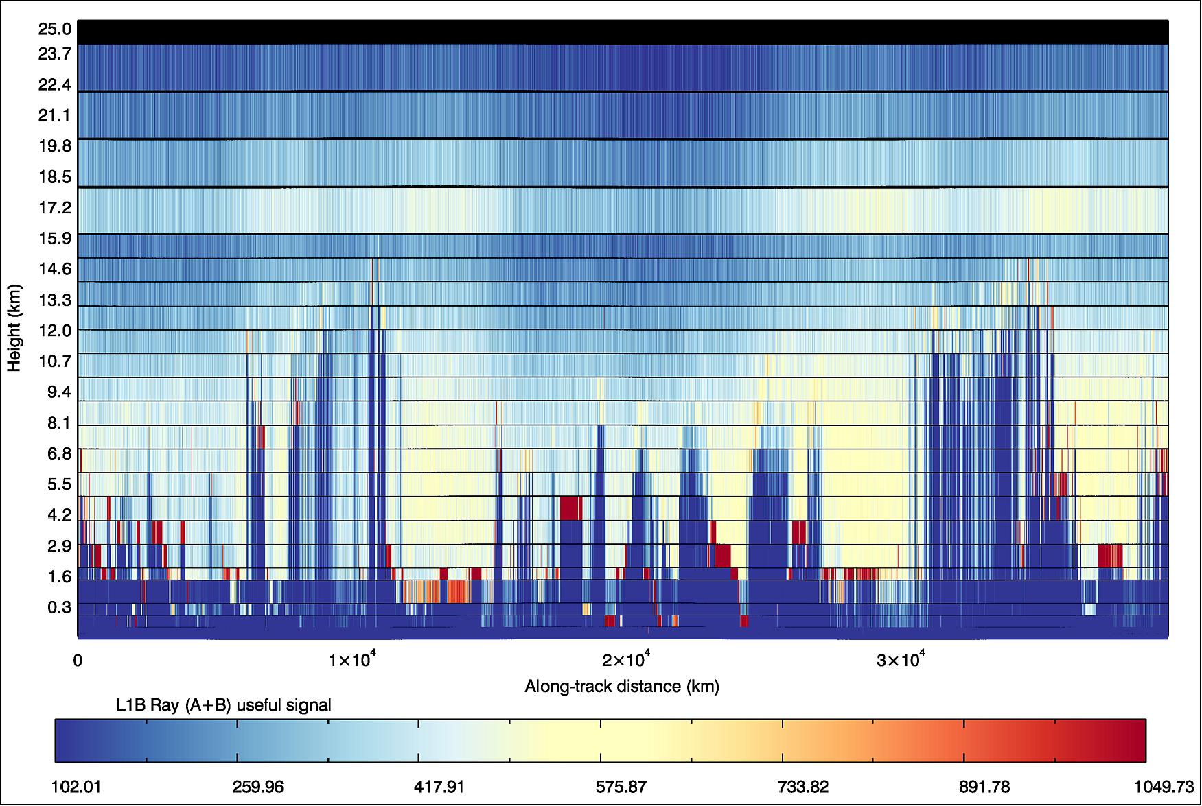
The primary data product of the mission was the Level 1B data set, comprising calibrated wind velocity observations for both Mie and Rayleigh channels, with various additional annotation parameters.
With the continuous mode laser operation, each observation profile was constructed by the averaging of N on-board accumulated measurements of P consecutive pulses. Typical figures for N and P are, respectively, 30 and 20, leading to an observation horizontal integration length of 90 km, with less than 1% data gap between successive observations (instead of 50 km in burst mode with 150 km data gap between observations). The different values provided in Table 3 corresponded to the horizontal integration length that needed to be considered in order to meet the wind velocity random error requirement.
The Level 1B products were going to be globally delivered to a number of meteorological service centers within 3 hours after sensing (NRT service) and for selected regions within 30 minutes after sensing (QRT service, e.g. within 30 minutes).
Higher level products included information on clouds and aerosols optical properties (Level 2A), as well as consolidated horizontal line-of-sight wind observations (Level 2B), after temperature/pressure corrections and scene classification of the measurements within one observation. The assimilation of Level 2B data in the ECMWF operational forecast model provided the so-called Aeolus assisted wind products (Level 2C).
Product | Contents | Typical size/orbit |
Level 0 | Raw ‘science’ source packets including unprocessed instrument and platform telemetry, packet quality parameters | ~60 MByte |
Level 1B | Engineering calibrated wind velocity data (preliminary one component wind observations), including viewing geometry, scene geolocation and ground echo data | ~87.5 MByte |
Level 2A | Supplementary data product for cloud and aerosol optical properties (layer backscatter and extinction coefficient, top /base heights, optical depth....), including viewing geometry, scene geolocation data and error quantifiers | ~ 20 MByte |
Level 2B | Consolidated geolocated wind observations after atmospheric corrections and scene classification, including additional geophysical parameters and error quantifiers | ~ 42 MByte |
Level 2C | Aeolus assisted wind data, result of NWP assimilation processing, including vertical wind vector profiles (u & v components) and supplementary geophysical parameters | ~ 46 MByte |
Preparatory Campaigns for the Verification of the Measurement Principle
An A2D (Aladin Airborne Demonstrator) instrument was developed by EADS Astrium SAS to demonstrate and validate the capability of ALADIN. Installation and testing of the A2D on ground was performed with first atmospheric signal in October 2005. The two functional test-flights (Oct. 18 and 20, 2005) were performed with signal from clear atmosphere, clouds and ground. The measurements demonstrated that the aircraft integration and testing was successful. These were probably the first flights of an airborne, direct-detection Doppler wind lidar worldwide. 77) 78) 79) 80) 81) 82) 83) 84)
Campaign | Location | Period | Duration |
AGC-1 (Aeolus Ground Campaign-1) | DWD-MOL, | October 2006 | 4 weeks (+1 week) |
AGC-2 | DWD Lindenberg, Germany | July 2007 | 2 weeks (+1 week) |
Aeolus flight campaign 1 | DLR Oberpfaffenhofen, | November 2007 | 15 days / 25 hours |
Aeolus flight campaign 2 | DWD Lindenberg, Germany and other European sites | Spring 2008 | 2 weeks (25 hours) |
• In August 2009, DLR performed a campaign on Germany’s highest mountain, the Zugspitze. The clean mountain air was needed to provide the right conditions to investigate what effects the atmosphere would have on the return signal of the satellite's core instrument. The objective was to accurately measure the spectrum of the backscattered laser light from a lidar to further improve the measurements of wind speed. The experiments were carried out by DLR at the Environmental Research Station Schneefernerhaus observatory, which is located 2650 m above sea level. The science measurements were done with the A2D. 85)
• In March 2010, a DLR team conducted a flight campaign of 2 weeks in Iceland, performing a total of six flights over Iceland, over the ocean between Iceland and Greenland and over the Greenland glacier plateau. The aim of this DLR-led campaign with A2D was to investigate details of the instrument operations strategy and to refine the ADM-Aeolus data processors that will provide the mission's wind products. 86) 87)
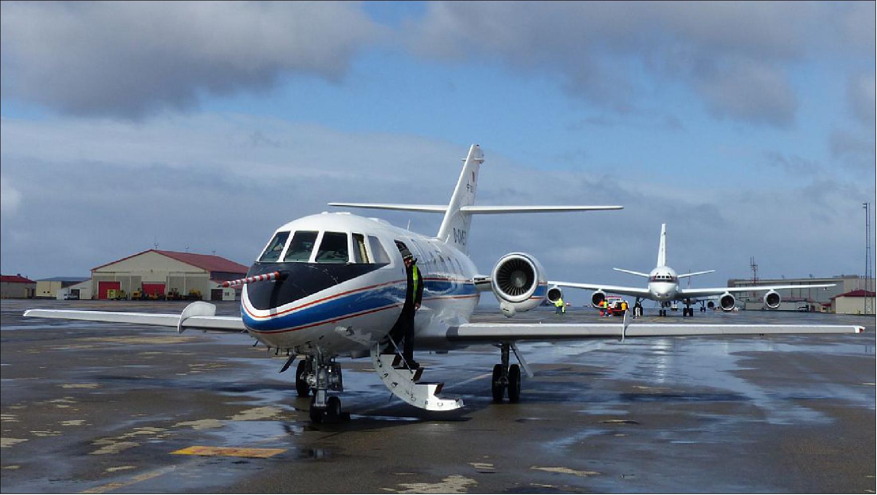
Two different wind lidar instruments – the A2D (ALADIN Airborne Demonstrator), and a reference wind lidar operating at an infrared wavelength of two microns – were operated onboard DLR's Falcon 20E aircraft, and both performed well throughout the campaign.
• In May 2015, DLR is using its Falcon research aircraft to test an aircraft-based version of the wind measurement laser technology. From their temporary base in Iceland, the researchers are flying over the ice sheets of southern Greenland. As they do so, another proven wind lidar that was used over Iceland to take volcanic ash measurements during the eruption of Eyjafjallajökull in 2010 was used as a reference and comparison instrument on board the Falcon. The United States aerospace agency, NASA, is also in Iceland, supporting the campaign with its own research aircraft and measurement equipment. 88)
- Windiest place on Earth: Europe's weather systems are formed in the arctic polar region around Iceland and Greenland. Small anomalies that occur where cold air masses from the polar regions meet warmer air masses can lead to the development of weather systems. The Icelandic depressions here are well known. In addition, the polar region of Greenland is of particular interest in climate research because of the rising temperatures in the Arctic and the associated retreat of polar ice sheets. "In the current research flight campaign, we are calibrating the new wind lidar above the extensive ice fields of Greenland – testing our algorithms in the process – to make sure that, later on, everything runs smoothly in space," says Oliver Reitebuch from the DLR Institute of Atmospheric Physics. In particular, the southern tip of Greenland – the windiest place in the world – is the perfect testing ground for the new wind measurement technology, as it is especially challenging, with pronounced tip jets and strong jet streams.
- NASA and DLR joint flights: "We are conducting several flights per day above the permanent ice of Greenland and, in doing so, are acquiring comparative data from a summit station operated by our US research colleagues at an altitude of 3200 m," says DLR test pilot Philipp Weber. After taking off from Iceland, the Falcon crew makes a refuelling stop at Kangerlussuaq in Greenland and then spends two hours crisscrossing Greenland. In total, some 10 test flights above Greenland are planned, which will mostly take place in coordination with the NASA DC-8 research aircraft. The data from the NASA DC-8 and the DLR Falcon will then be compared. Two lidar instruments are being used on board the NASA DC-8, in addition to measurement probes that are ejected from the aircraft via a chute.
- Scattered light makes wind fields visible: At present, the major wind fields over the oceans are still detected optically by weather satellites tracking cloud movements, or measured indirectly using radar signals reflected by the wave motion on the surface of oceans. "The wind lidar measurements will enable the project team to directly measure wind speeds from ground level up to an altitude of 20 km with significantly greater accuracy. Depending on the altitude, the project can achieve a resolution of between 500 to 1000 m while doing so," explains Reitebuch. "With the Doppler lidar –a laser pulse sequence is emitted into a wind field at a precisely defined wavelength. Depending on the movement of the wind field, the light is reflected back with a very small change in wavelength. From this, the team can determine the wind speed," continues Reitebuch. Using this technology, the DLR researchers will be capable of accurately determining changes as small as one ten billionths of a wavelength.
- Small anomalies with large effects on the weather: In addition to testing the wind lidar above Greenland, the DLR atmospheric researchers are acquiring data on the formation and development of Icelandic depressions. The researchers hope to better understand how low-pressure systems arise from small anomalies over Iceland, Greenland and the North Atlantic in a short time. "From Iceland, measurements can be performed in the strong jet streams over the North Atlantic. Detailed knowledge of the wind distribution is particularly important because a lack of wind data very quickly leads to errors in weather forecasting models," says Reitebuch. "These errors affect the accurate forecasting of the development of low-pressure systems, which often move towards Europe and, due to their high winds and heavy rainfall, have a significant effect on our daily lives."
- The DLR ADM (Atmospheric Dynamics Mission) research flight campaign over Iceland and Greenland is a DLR contribution to the ESA ADM-Aeolus mission. Involved in this mission are the DLR Institute of Atmospheric Physics, DLR Flight Experiments, ESA and the University of Leeds, which has a wind lidar installed at the summit station in Greenland for the mission to perform comparison measurements from the ground. This mission is being carried out in cooperation with NASA. For the first time in the world, four wind lidar instruments on two aircraft are being used at the same time.
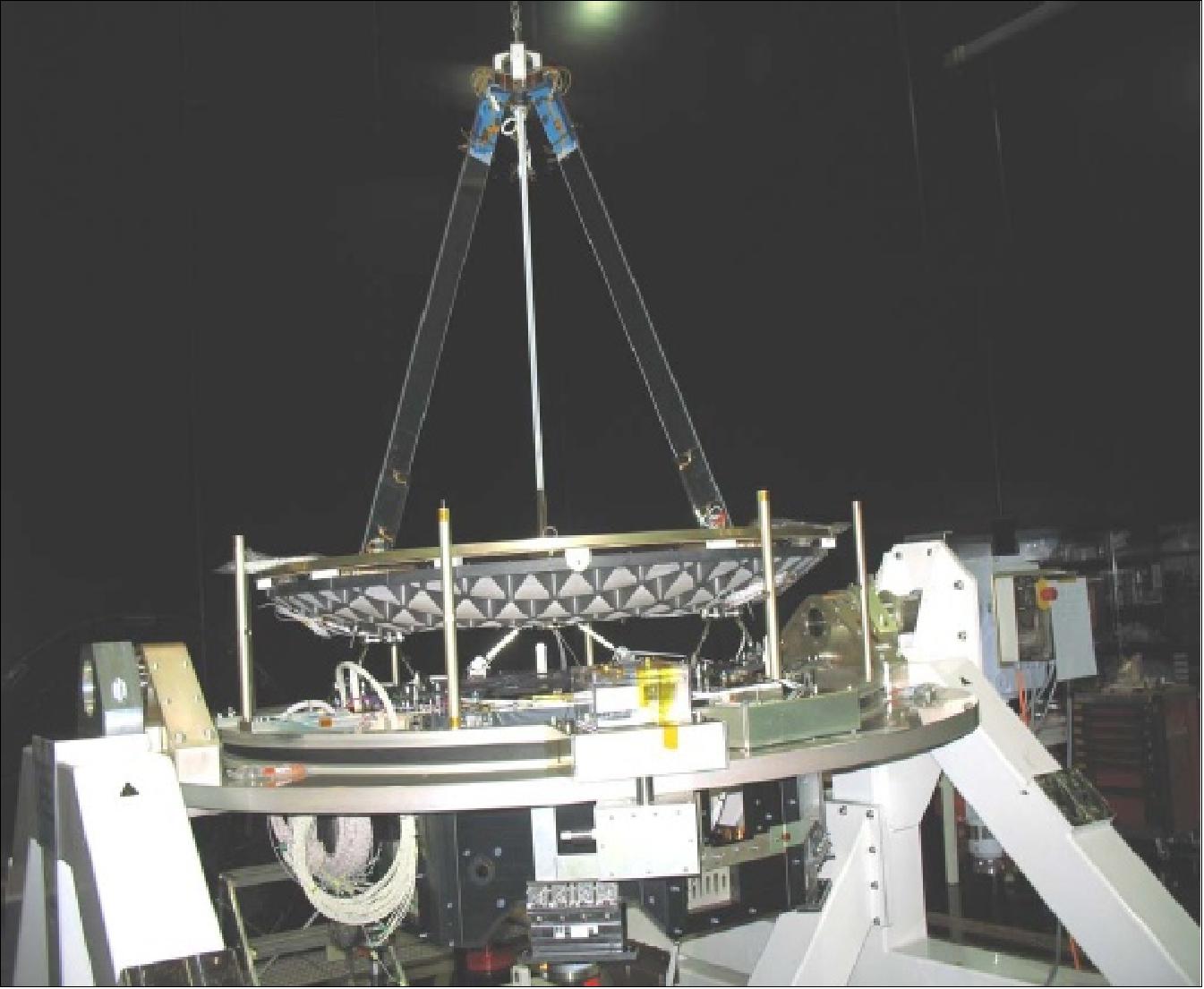
Design and Setup of the ALADIN Airborne Demonstrator
The core of the A2D was based on the ALADIN receiver and transmitter from the pre-development program of ESA and was therefore representative of the actual satellite instrument. The optical receiver of the A2D was space qualified with respect to its thermal vacuum and vibration environment during the pre-development phase.
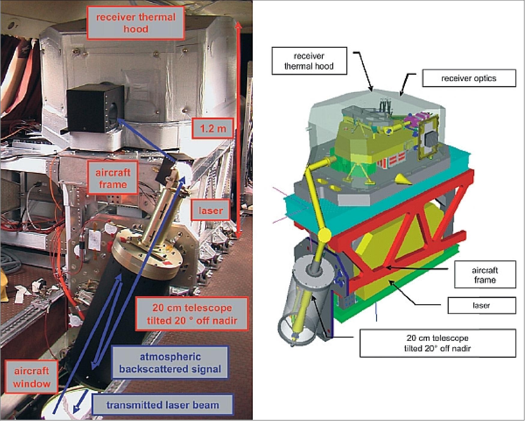
The A2D was a nonscanning lidar as the satellite instrument. Thus, only one LOS component of the three-dimensional wind vector is measured in contrast to most other direct-detection wind lidars, which are equipped with a scanning device. The LOS wind was measured perpendicular to the aircraft roll axis, with an off-nadir angle of 208. The A2D was designed to be operated on the DLR Falcon 20 aircraft, a twin-engine jet with a pressurized cabin allowing a maximum payload of 1.1 ton, a flight altitude of up to 12 km, and range of up to 3700 km.
The installation of the A2D inside the Falcon aircraft is shown in Figure 42 with the telescope, the mechanical aircraft frame, and the thermal hood of the receiver system. The mechanical frame holding the telescope, receiver, and laser was mounted via vibration-damping shock mounts to the seat rails of the aircraft. The mechanical frame of the 10.6 µm heterodyne wind infrared Doppler lidar, which has proven its aircraft vibration-damping behavior needed for coherent detection, was adapted to hold the A2D laser, optical receiver, and telescope.
The laser beam was directed toward the atmosphere via a window in the bottom fuselage of the aircraft cabin. The electronic units operating the A2D are installed in 19 inch aircraft racks and are controlled by two operators. The total volume of the system was 3 m3, the mass is 550 kg, and the mean power consumption was 2.5 kW. Finite element simulations were performed to minimize the overall weight, providing high stiffness for the transmit and receive optical path, and to prove airworthiness.
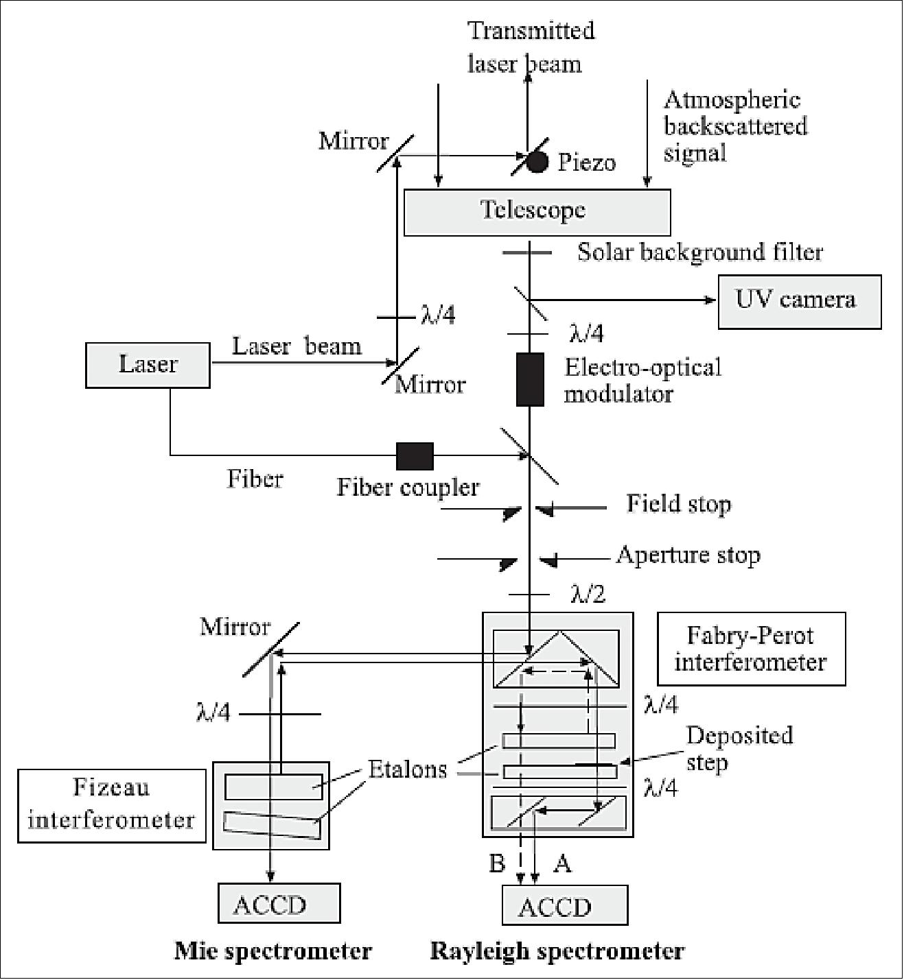
Optical design overview: The narrowband single-frequency laser pulses at 354.89 nm vacuum wavelength were generated by an Nd:YAG laser. The circularly polarized laser pulses were transmitted via three reflecting mirrors through the aircraft window (or one reflecting mirror in case of ground operation) toward the atmosphere. The last reflecting mirror was placed on the telescope optical axis and thus a coaxial transmit–receive system was obtained.
The backscattered photons from the atmosphere were collected by a 20 cm aperture Cassegrain telescope and directed to the optical receiver via an optical relay with two lenses and two mirrors. After passing the front optic with field and aperture stop, the light was directed toward the two spectrometers. The Rayleigh spectrometer used the double-edge technique with a sequential Fabry–Perot interferometer, whereas the Mie spectrometer was based on a Fizeau interferometer. For both the Rayleigh and the Mie spectrometer, an ACCD (Accumulation CCD) detector was used, and the electronic signal was digitized after preamplification. The sequential implementation of the Fabry–Perot interferometer and the ACCD are patented by Astrium.
The optical beam path with about 60 optical elements and the alignment sensitivities were studied in detail with an optical ray-tracing model. The principle layout of the A2D optical design is shown in Figure 43. The main instrument parameters for the satellite ALADIN and the A2D are summarized in Table 8.
Parameter | ALADIN on Aeolus | A2D |
Platform | Satellite | Container or DLR Falcon aircraft |
Altitude | 320 km | Ground or 8–12 km flight altitude |
LOS pointing | 37.6º off nadir | 0º, 15–20º off zenith (ground) |
Minimum vertical resolution | 250 m for 2.1 µs at 37.6º off nadir | 315 m for 2.1 µs at 0º zenith |
Laser transmitter | Nd:YAG, frequency-tripled, diode-pumped | |
Wavelength | 354.9 nm | 354.89 nm |
Operation | Burst mode | Continuous |
Pulse repetition rate | 100 Hz | 50 Hz |
Energy per pulse | 129 mJ | 55–65 mJ |
Laser line width | < 50 MHz (FWHM) | 45 MHz (FWHM) |
Pulse-to-pulse frequency stability in the UV | < 4 MHz rms over 7 s | < 1.8 MHz rms over 14 s |
Laser divergence | 12 µrad | 80–90 µrad for ±3σ, 99.7% |
Laser beam diameter | 1.5 m | 16 mm (99.7%) |
Laser output polarization | Circular left | |
Laser internal reference path | Free path with aberration generator | Multi mode fiber with polarizer |
Telescope and receiver | Transceiver telescope; | Receiver Cassegrain telescope |
Telescope diameter | 1.5 m | 0.2 m |
Receiver FOV | 19 µrad | 100 µrad |
Background blocking filter bandwidth FWHM | 1 nm | 2.6 nm |
Mie spectrometer | Fringe-imaging Fizeau interferometer, 16 spectral channels | |
Rayleigh spectrometer | Double-edge Fabry–Perot interferometer, 2 filters, sequential | |
Detector | ACCD (Accumulation CCD), quantum efficiency 0.85 | |
Development Status of the Spacecraft and ALADIN
• August 16, 2018: Measuring 4.5 m across, this relatively small antenna in Australia, dubbed NNO-2, will be the first to hear from the soon-to-be-launched Aeolus satellite, the first ever to measure winds on Earth from Space. 89)
- Aeolus’ first steps after separation will include the automatic unfolding of its solar ‘wings’ and turning its antenna to face Earth to start sending signals. Only then will teams on the ground be able to get any sign from the satellite that all is well.
- Since 2015, NNO-2 has been pointing to space, listening for signals from rockets and newly launched satellites and transmitting instructions and commands to them from engineers on Earth.
• August 9, 2018: As preparations for the launch of ESA’s latest Earth Explorer continue on track, the team at Europe’s Spaceport in French Guiana had bid farewell to the Aeolus satellite as it was sealed from view in its Vega rocket fairing. Liftoff was set for 21 August at 21:20 GMT (23:20 CEST). 90)
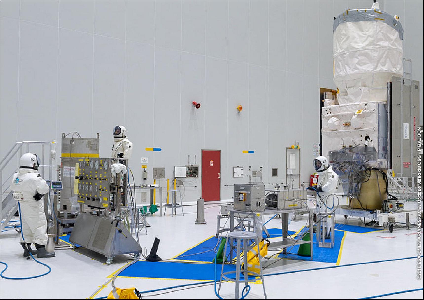
- Since its arrival at the launch site in early July, Aeolus was thoroughly tested and fuelled with hydrazine.
- Like all of ESA’s Earth Explorer missions, Aeolus filled a gap in our knowledge of how our planet works and showed how novel technology could be used to observe Earth from space.

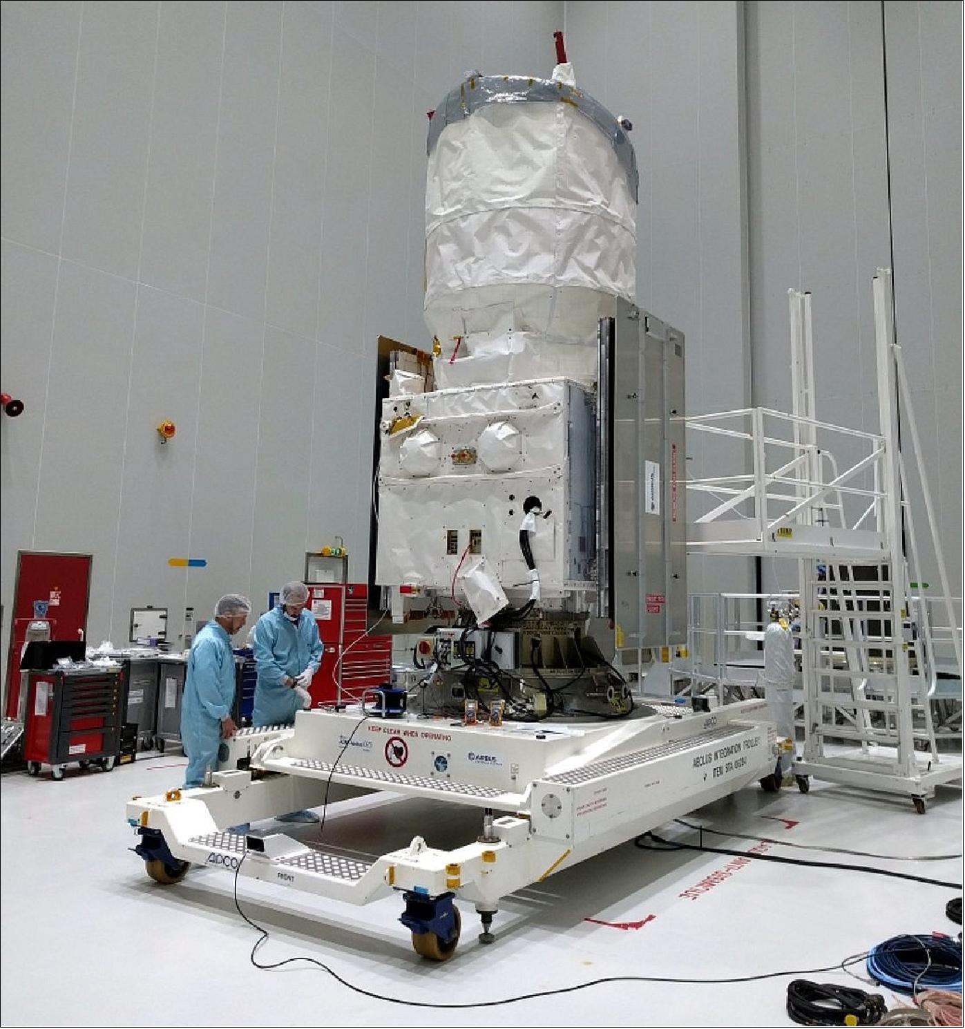
• August 2, 2018: With liftoff less than three weeks away, ESA’s Aeolus satellite had been fuelled and was almost ready to be sealed within its Vega rocket fairing. 91)
• July 24, 2018: The launch of Aeolus — ESA’s mission to map Earth’s wind in realtime — was getting close, with the satellite due for lift-off on 21 August from Europe’s Spaceport in Kourou, French Guiana. With the wind in their sails, mission teams are busily preparing this unique satellite for its upcoming journey. 92)
- Aeolus carried a sophisticated atmospheric laser Doppler instrument, dubbed ALADIN. Combining two powerful lasers, a large telescope and extremely sensitive receivers, it was one of the most advanced instruments ever put into orbit.
- Currently one of the biggest challenges in making accurate weather predictions is gathering enough information about Earth’s wind. Aeolus was the first-ever satellite to directly measure winds from space, at all altitudes, from Earth's surface through the troposphere and up 30 km to the stratosphere — providing information that significantly improved the quality of weather forecasts.
- Paolo Ferri, Head of Mission Operations at ESA adds, “The Aeolus mission will be a wonderful addition to our fleet of satellites that continually observe Earth bringing us incredible insights into our planet, in particular into the complex world of atmospheric dynamics and climate processes — systems that not only affect our everyday lives but also have huge consequences for our future.”
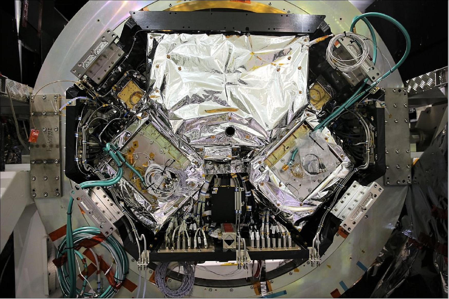
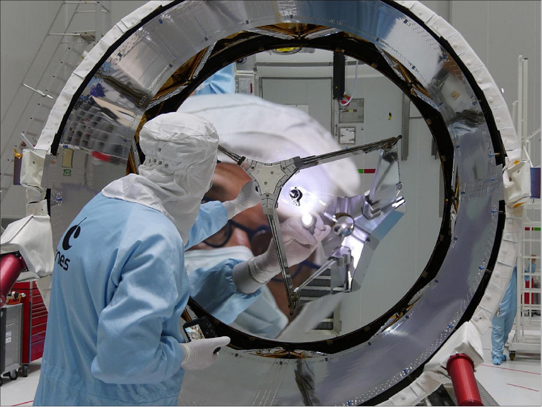
• July 10, 2018: With the campaign to launch ESA’s Aeolus wind satellite on 21 August well underway, the satellite’s telescope had been opened and inspected to make sure it was perfectly clean and shiny. 93)
- While Aeolus’ novel laser technology was arguably the sexy part of the instrument, its telescope, which measured around 1.5 m across, was pretty dominant and equally important. It was used to collect backscattered light from the atmosphere and direct it to the receiver. In short, the laser system generated a series of short pulses of ultraviolet light which were beamed down into the atmosphere. The telescope collected the light backscattered from particles of gas and dust in the atmosphere. The time between sending the light pulse and receiving the signal back determined the distance to the ‘scatterers’ and therefore the altitude above Earth. As the scattering particles were moving in the wind, the wavelength of the scattered light was shifted by a small amount as a function of speed. The Doppler wind lidar measured this change so that the velocity of the wind could be determined.
- It was clearly important to make sure that the instrument was absolutely spotless, so engineers at the launch site in Kourou had first turned to the telescope and given it a close inspection.
• July 6, 2018: Having set sail from France on 15 June - Global Wind Day, ESA’s Aeolus wind satellite arrived safe and sound at the launch site in French Guiana. - While almost all satellites travel by aircraft, Aeolus’ journey was rather different – it travelled all the way across the Atlantic from Saint Nazare, western France to the Port of Cayenne, French Guiana by ship. 94)
- Aeolus carried one of the most sophisticated instruments ever to be put into orbit. A 12-day journey was undertaken to avoid potential damage caused by air re-pressurization during descent had the satellite travelled by air – a quicker but decidedly riskier option.
- Upon its long-awaited arrival, the team unloaded Aeolus and its support equipment. The containers were then carefully positioned on a truck to be transported to the launch site about 60 km away, where the satellite container was moved into the airlock, to stabilize after its long journey.
- The satellite was then removed from its container, placed on its integration trolley for testing and connected to its electrical support equipment. Initial checks indicate that Aeolus has withstood its journey from France in good condition.
- ESA’s Aeolus project manager, Anders Elfving, said, “We are obviously all extremely pleased that Aeolus has now arrived at the launch site. An awful lot of work and planning went into making sure it arrived safe and sound – now it’s full steam ahead for preparing the satellite for liftoff on 21 August.”
- A range of checks were carried out on the satellite in the cleanroom before the scheduled liftoff on a Vega rocket on 21 August at 21:20 GMT (23:20 CEST) from Europe’s spaceport near Kourou.
• June 15, 2018: Today was Global Wind Day, which couldn’t have been more apt for ESA’s Aeolus wind satellite to begin its voyage to the launch site in French Guiana. And, while almost all satellites journey by aircraft, Aeolus was different, it travelled by ship. 95)
- Since the ALADIN instrument is sensitive to pressure change, ESA and Airbus Defence and Space engineers decided that the safest way for it to journey from France, where it had been going through testing, to French Guiana would be by ship.
- Denny Wernham, ESA’s Aeolus instrument expert, explains, “Going by ship may seem a little strange, after all it will take around 12 days to get there instead of a matter of hours, but if, for whatever reason, the aircraft had to descend rapidly and there was a sudden increase in air pressure, Aeolus’ instrument could be damaged."
- “It was designed, of course, to allow for the pressure drop during launch ascent so that it could be taken into orbit, but not for a fast descent. So basically, once it’s up, it’s up."
- “So, today we see our beloved satellite and all of its support equipment being loaded onto a ship in Saint Nazaire in western France and set forth across the Atlantic. And, indeed, it is kind of ironic: our high-tech wind satellite is travelling by a means that many years ago relied on the wind.”
- Aeolus had, without doubt, been a challenging satellite mission to develop. Nevertheless, this long-awaited mission was now set to not only improve our understanding of how the atmosphere works and contribute to climate change research, but has also helped to predict extreme events such as hurricanes. It has also helped to better understand and model large-scale wind patterns driving weather such as El Niño.
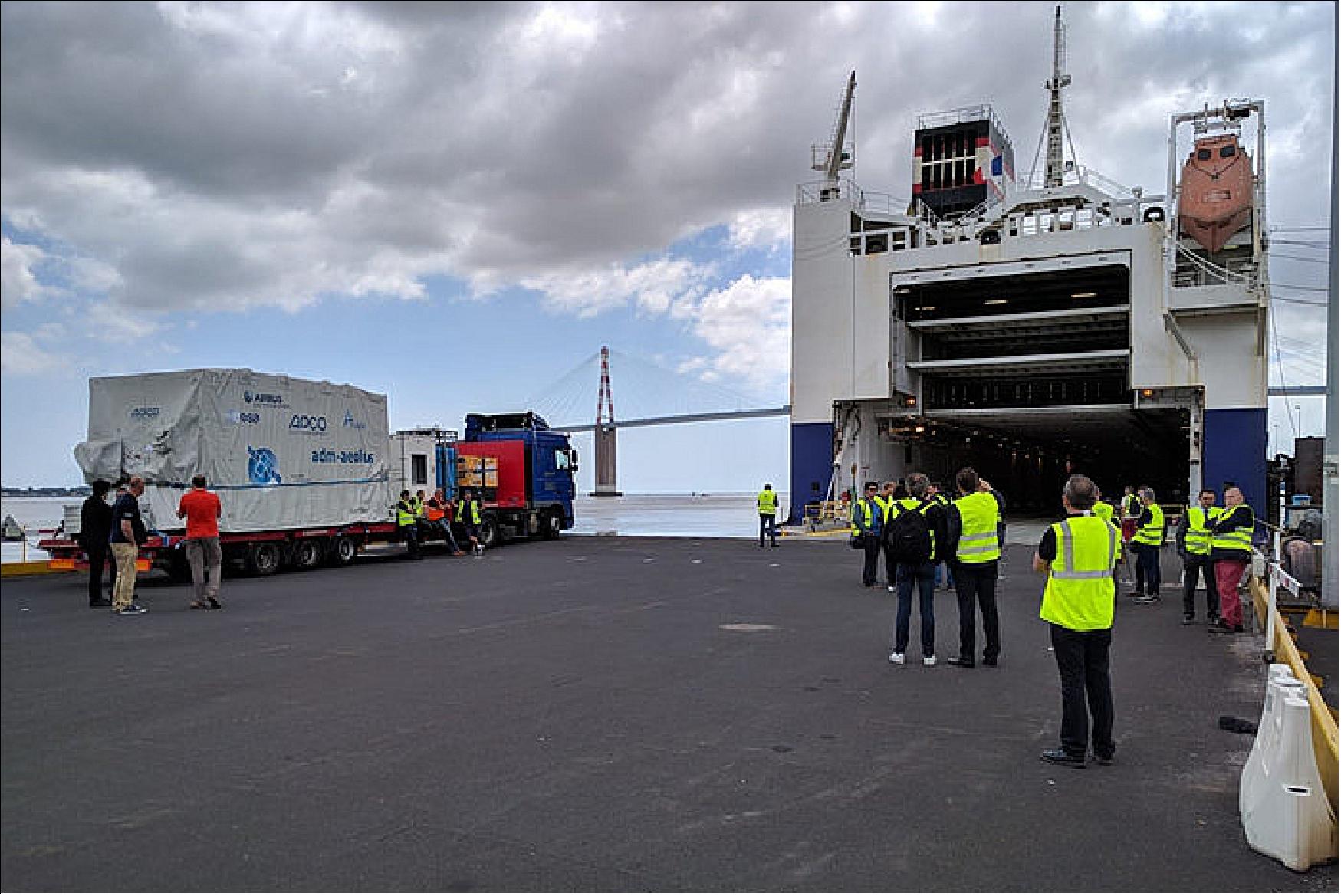
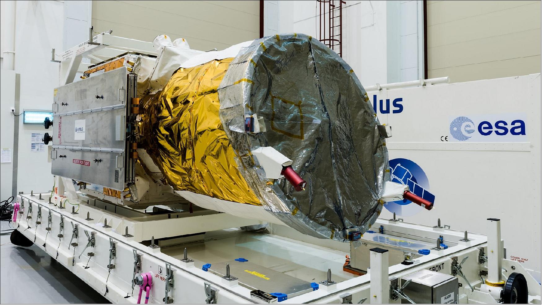
• June 5, 2018: Like all of the Earth Explorers, Aeolus was built to show how cutting-edge space technology can shed new light on the intricate workings of our planet. This pioneering satellite used powerful laser technology that probes the lowermost 30 km of our atmosphere to yield vertical profiles of the wind as well as information on aerosols and clouds. This not only improved our understanding of how the atmosphere works and contributed to climate change research, but also helped to predict extreme events such as hurricanes and El Niño. 97)
• February 7, 2018: ESA’s Aeolus satellite was particularly tricky to build. One of the main stumbling blocks was getting its lasers to work in a vacuum, but recent tests on the satellite showed that the vacuum or temperature of space wouldn't have gotten in the way of Aeolus measuring Earth’s winds. 98)
- The ALADIN instrument shot pulses of ultraviolet light down into the atmosphere and measured the backscattered signals from molecules and aerosols to profile the world’s winds.
- “This will be the first time that we will be able to directly measure profiles of the global wind field from space in cloud-free conditions. It has been a major challenge for us all – our ESA engineers, industry, our Member States – to overcome many technical and programmatic challenges. I am grateful to everyone for having gone through this and for having trust in ESA to finally make it happen. We are now very close to seeing the fruits of a long endeavor,” said Josef Aschbacher, ESA’s Director of Earth Observation Programs.
- These vertical slices through the atmosphere, along with information on aerosols and clouds, advanced our knowledge of atmospheric dynamics and contributed to climate research.
- Since Aeolus delivered measurements almost in realtime, it was also set to provide much-needed information to improve daily weather forecasts.
- The satellite’s novel technology was under development for some years, but issues with the laser component of the instrument and with the optics, which have to survive exposure to the high-intensity laser pulses, were eventually resolved, and in 2016 the instrument was finally ready.
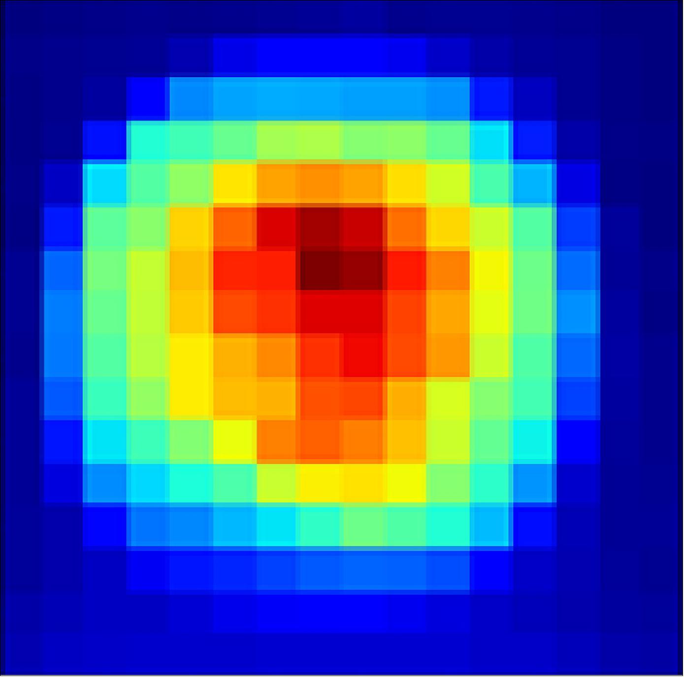
- ALADIN was then added to the satellite in the UK, after which the assembly was moved to France where it was shaken to simulate the rigors of liftoff.
- The last round of tests was carried out in CSL (Centre Spatial de Liège), Belgium, and involved putting the satellite in a thermal–vacuum chamber for almost two months (Figure 52).
- Once the satellite was safely inside, the air was pumped out and the chamber cooled by liquid nitrogen to simulate the environment of space – and then Aeolus was put through its paces.
- ESA’s Aeolus project manager, Anders Elfving, said, “The test was exceptionally complex, not only because it was a tight fit with the satellite filling up most of the space in the chamber, but also because we had to make sure that the whole instrument’s performance is tip-top. It was an extremely technical and delicate undertaking that included firing ALADIN’s lasers at full power. The satellite as a whole came through with flying colors, and we are particularly pleased that the two laser transmitters performed brilliantly.”
- With this milestone behind it, Aeolus was returned to France where it had a few final tests before being shipped across the Atlantic to Europe’s Spaceport in French Guiana for launch on a Vega rocket in the autumn.
- ALADIN was built by Airbus SAS in Toulouse, France, the satellite by Airbus Ltd. in Stevenage, UK, and the laser transmitters by Leonardo SpA in Florence and Pomezia, Italy.
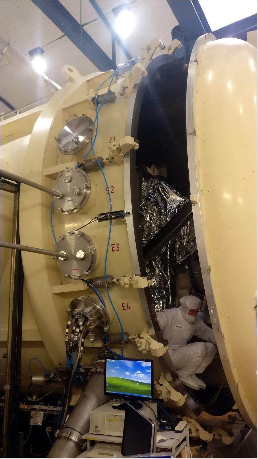
• November 2, 2017: With liftoff on the horizon, ESA’s Aeolus satellite was going through its last round of tests to make sure that this complex mission was going to work in orbit. Over the following month, it was sitting in a large chamber that had all the air sucked out to simulate the vacuum of space. 99)
- With these difficulties in the past, the satellite is now undergoing final testing in Belgium before it is shipped to French Guiana for liftoff, which is scheduled for the middle of next year.
- After having spent this spring at Airbus Defence and Space in Toulouse, France, where it was checked that it could withstand the vibration and noise liftoff and its ride into space, Aeolus was at the Centre Spatial de Liège since May. - There, it had just been enclosed in the thermal–vacuum chamber for the next 30 days or so.
- With the satellite safely inside, the chamber door was closed a few days later and the air was pumped out to create a vacuum.
- Denny Wernham, ESA’s Aladin instrument manager, said, “It takes some time for the air and outgassing from the satellite to be pumped out of the chamber, but Aeolus finally faced ‘hard vacuum’ on 31 October."
- “Tests are scheduled to run continuously over the next 33 days. We are particularly keen to see how well the laser transmits its pulses of ultraviolet light and the alignment of the instrument in this environment."
- Once these tests were done, the satellite was transported back to Toulouse for final checks before being shipped across the Atlantic to Europe’s Spaceport in French Guiana for launch on a Vega rocket.
• January 30, 2017: The road to realizing ESA’s Aeolus mission may have been long and bumpy, but developing novel space technology is, by its very nature, challenging. With the satellite equipped with its revolutionary instrument, the path ahead was much smoother as it headed to France to begin the last round of tests before being shipped to the launch site at the end of 2017. 100)
- Aeolus carried one of the most sophisticated instruments ever to be put into orbit: ALADIN, with two powerful lasers, a large telescope and very sensitive receivers. It shot pulses of ultraviolet light down into the atmosphere to profile the world’s winds. This was a completely new approach to measuring the wind from space, which usually involved tracking cloud movement, measuring the roughness of the sea surface or inferring wind from temperature readings.
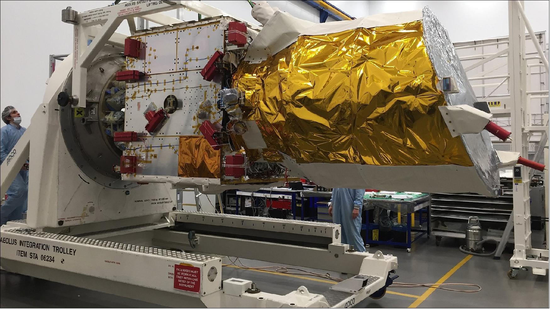

The ADM-Aeolus mission did not only advance our understanding of atmospheric dynamics, but also provided much-needed information to improve weather forecasts.
The satellite carried the first wind lidar in space, which could probe the lowermost 30 km of the atmosphere to provide profiles of wind, aerosols and clouds along the satellite’s orbital path.
The laser system emitted short powerful pulses of ultraviolet light down into the atmosphere. The telescope collected the light that was backscattered from air molecules, particles of dust and droplets of water.
The receiver analysed the Doppler shift of the backscattered signal to determine the speed and direction of the wind at various altitudes below the satellite.
These near-realtime observations improved the accuracy of numerical weather and climate prediction and advanced our understanding of atmospheric dynamics and processes relevant to climate variability.
- Aeolus was built mainly to advance our understanding of Earth. These vertical slices through the atmosphere, along with information on aerosols and clouds, advanced our knowledge of atmospheric dynamics and contribute to climate research. - However, Aeolus also had a very important practical role to play because its measurements were delivered rapidly, improving weather forecasts. After its long development, ALADIN was finally ready to join the satellite at Airbus Defence and Space in Stevenage in the UK in August last year.
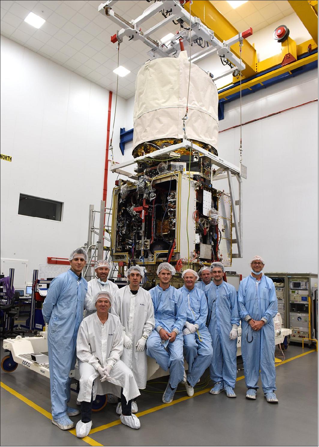
- With the satellite complete, it was time move it to Toulouse where it would have been tested to make sure that it can withstand the vibration and noise of liftoff. — After this, ADM-Aeolus was going to Liege in Belgium to be checked in a thermal–vacuum chamber.
• August 2, 2016: After many years in development, ALADIN – the Doppler wind lidar to be carried on the Aeolus satellite – was ready to be shipped from Toulouse, France, to the UK to be installed on the satellite in preparation for liftoff by the end of 2017. Aeolus was the first satellite mission to probe the wind globally. These vertical slices through the atmosphere, along with information on aerosols and clouds, were going to advance our knowledge of atmospheric dynamics and contributed to climate research. 101)
- Its state-of-the art ALADIN instrument incorporated two powerful lasers, a large telescope and very sensitive receivers. The laser generated ultraviolet light that was beamed towards Earth. This light bounced off air molecules and small particles such as dust, ice and droplets of water in the atmosphere. The fraction of light that was scattered back towards the satellite was collected by ALADIN’s telescope and measured.
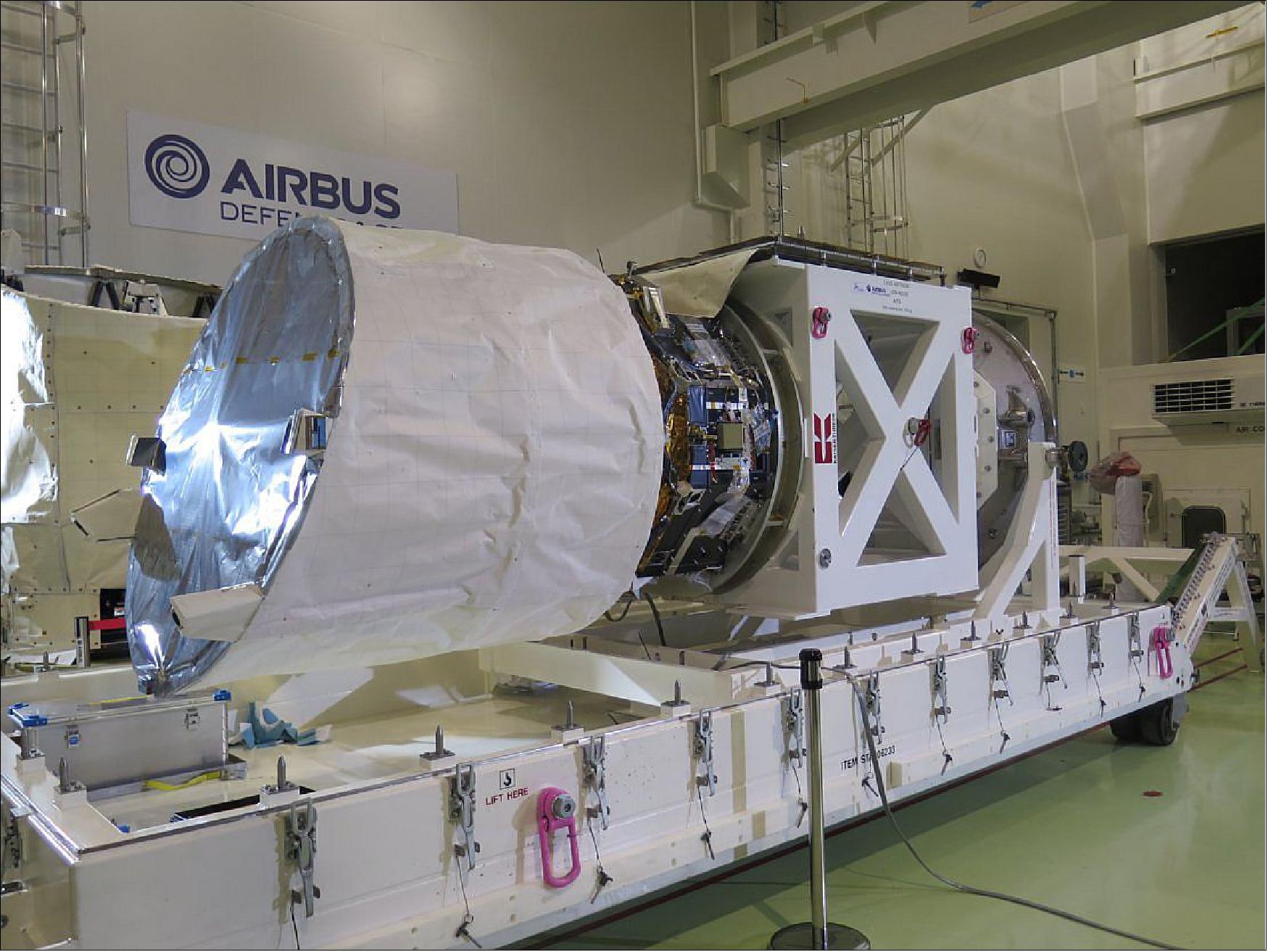
• 2016: The ALADIN instrument was fully integrated and both laser transmitters were aligned for optimal performance. The In-situ Cleaning Subsystem was tested together with the latest satellite flight software. The satellite platform was finalized and checked out in preparation for mating with the ALADIN PLM. The Payload Data Ground Segment facilities were being prepared and undergoing tests. The Flight Operations Segment facilities was also being readied. 102)
• April 22, 2015: A lot of time has gone into developing the technology involved and testing both lasers. Despite numerous setbacks, in particular issues associated with them working properly in a vacuum, engineers at Selex-ES in Italy persevered. Thanks to their dedication and ingenuity, a major milestone for the mission had been achieved. Both lasers had then been delivered to Airbus Defence and Space in Toulouse, France, ready to be integrated into the rest of ALADIN. 103)
- Despite a number of setbacks, this cutting-edge piece of technology is now ready to be integrated into the rest of the satellite’s instrument – a Doppler wind lidar called ALADIN. — ADM-Aeolus will provide profiles of the world’s winds as well as information on aerosols and clouds. These profiles will not only advance our understanding of atmospheric dynamics, but will also offer much-needed information to improve weather forecasts.
- Thanks to these collective efforts, the project can now focus on the instrument and satellite integration and testing. This means a launch of ADM-Aeolus spacecraft can be done in 2016.
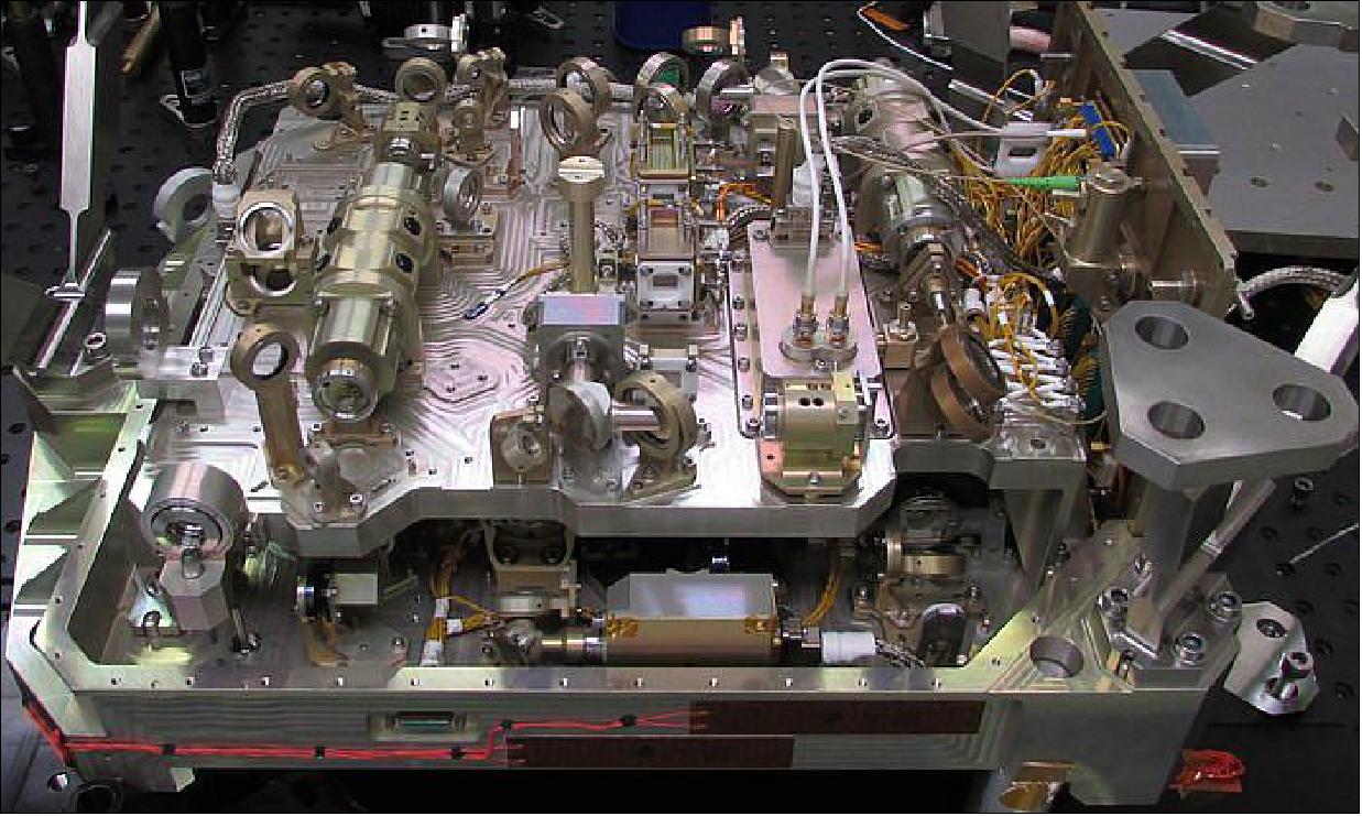
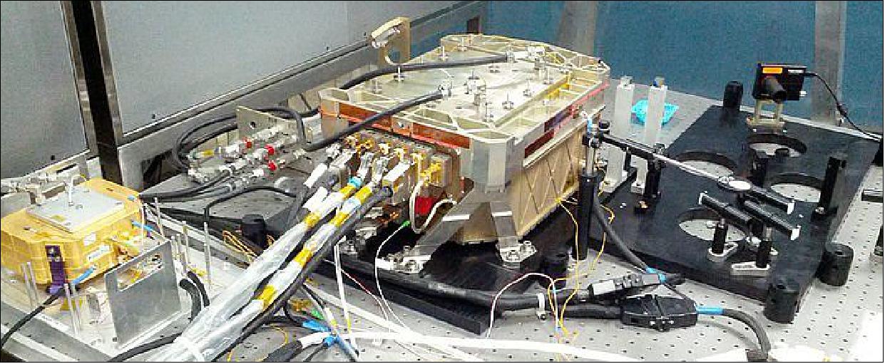
References
1) A. Heliere, E. Armandillo, Y. Durand, A. Culoma, R. Meynart, “Lidar Instruments for ESA Earth Observation Missions,” Proceedings of 22nd ILRC (International Laser Radar Conference), Matera, Italy, July 12-16, 2004, ESA SP-561, Vol. I, pp. 11-14
2) M. Endemann, P. Dubock, P. Ingmann, R. Wimmer, D. Morancais, D. Demuth, “The ADM-Aeolus Mission - the first wind-lidar in space,” Proceedings of 22nd ILRC (International Laser Radar Conference), Matera, Italy, July 12-16, 2004, ESA SP-561, Vol. II, pp. 953-956
3) P. Ingmann, J. Fuchs, J. Pailleux, A. Stoffelen, “The Atmospheric Dynamics Mission,” ESA Earth Observation Quarterly, No 66, July 2000, pp. 12-17
4) “Atmospheric Dynamics Mission,” ESA publication SP-1233 (4), July 1999
5) A. G. Straume-Lindner, P. Ingmann, M. Endemann, “Status of the Doppler Wind Lidar Profiling Mission ADM-Aeolus,” Proceedings of the 8th International Winds Workshop, Beijing, China, April 24-28, 2006, URL: http://www.eumetsat.int/groups/cps/documents/document/pdf_conf_p47_s5_01_straume_v.pdf
6) R. Wimmer, S. Willis, D. Morancais, F. Fabre, D. Demuth, “The ADM-Aeolus Mission - the first wind-lidar in space,” Proceedings of the 57th IAC/IAF/IAA (International Astronautical Congress), Valencia, Spain, Oct. 2-6, 2006, IAC-06-B1.2.08
7) Y. Durand, “Assessment Test Programme for the ALADIN Pump Laser Diodes,” 2nd ESA-NASA Working Meeting on Optoelectronics: Qualification of Technologies and Lessons Learned from Satellite LIDAR and Altimeter Missions,” June 21-22, 2006, ESA/ESTEC, Noordwijk, The Netherlands
8) A. G. Straume-Lindner, P. Ingmann, the members of the Aeolus Mission Advisory Group, “ADM-Aeolus: The First Space-Based High Spectral Resolution Doppler Wind Lidar,” Proceedings of IGARSS 2007 (International Geoscience and Remote Sensing Symposium), Barcelona, Spain, July 23-27, 2007
9) ADM-Aeolus Brochure, BR-236, Feb.2005, http://www.esa.int/esapub/br/br236/br236.pdf
10) D. Morançais, F. Fabre, M. Schillinger, Jean-Claude Barthès, M. Endemann, A. Culoma, Y. Durand, “ALADIN: The First European Lidar in Space,” Proceedings of the 5th International Conference on Space Optics, March 30 - April 2, 2004 ,Toulouse, France
11) “ADM-Aeolus Science Report,” ESA, SP-1311, April 2008, URL: http://esamultimedia.esa.int/docs/SP-1311_ADM-Aeolus_FINAL_low-res.pdf
12) K. Adamson, P. Bargellini, T. Nogueira, H. Nett, C. Caspar, “ADM-Aeolus: Mission Planning, Re-use Autonomy and Automation,” Proceedings of the SpaceOps 2010 Conference, Huntsville, ALA, USA, April 25-30, 2010, paper: AIAA 2010-1968
13) Anne Grete Straume, Paul Ingmann, Tobias Wehr, “ESA's Spaceborne Lidar Missions: Candidate and Selected Concepts for Wind, Aerosols and CO2 Monitoring,” Proceedings of the 26th International Laser Radar Conference (ILRC 26), Porto Heli, Peloponnesus, Greece, June 25-29, 2012
14) A M. Prezzavento, M Neal, “Aeolus AOCS Performance and Functional Validation,” roceedings of the GNC 2011, 8th International ESA Conference on Guidance, Navigation & Control Systems, Carlsbad (Karlovy Vary), Czech Republic, June 5-10, 2011
15) I. Vieira, C. Félix, C. Borda, C. Pepe, D. Temperanza, G. Furano, J. Edwards, Aeolus Magnetometer for Attitude Determination,” Proceedings of the 7th International ESA Conference on Guidance, Navigation & Control Systems (GNC 2008), June 2-5, 2008, Tralee, County Kerry, Ireland
16) S. Riva, E. Ferrando, R. Contini, R. Blok, R. vd Heijden, A. Caon, G. Labruyere, G. Strobl, W. Köestler, W. Zimmermann, “The ADM Aeolus Solar Array,” Proceedings of the 8th European Space Power Conference, Constance, Germany, Sept. 14-19, 2008, ESA SP-661, Sept. 2008
17) D. Pecover, “Functional Verification Of the ADM-AEOLUS Autonomy Requirements,” Proceedings of the SpaceOps 2010 Conference, Huntsville, ALA, USA, April 25-30, 2010, paper: AIAA 2010-2013
18) P. Bargellini, P. P. Emanuelli, S. Mejnertsen, R. Gessner, David Pecover, “ADM-Aeolus: an Innovative Operations Concept,” Proceedings of the SpaceOps 2006 Conference, Rome, Italy, June 19-23, 2006, paper: AIAA 2006-5506
19) http://www.esa.int/esaLP/LPadmaeolus.html
20) “The ADM-Aeolus Workshop Summary,” Sept. 26-28, 2006, ESA/ESTEC, Noordwijk, The Netherlands, http://esamultimedia.esa.int/docs/ADM-Aeolus_Workshop_Summary.pdf
21) M. Endemann, “The Aeolus Mission,” The 2nd ESA-NASA Working Meeting on Optoelectronics: Qualification of Technologies and Lessons Learned from Satellite LIDAR and Altimeter Missions,” June 21-22, 2006, ESA/ESTEC, URL: https://escies.org/webdocument/showArticle?id=356&groupid=6
22) Phil McGoldrick, Richard Wimmer, Steven Willis, Didier Morancais, Frederic Fabre, Dietmar Demuth, “The ADM-Aeolus Mission – the first wind-lidar in space,” Proceedings of the 59th IAC (International Astronautical Congress), Glasgow, Scotland, UK, Sept. 29 to Oct. 3, 2008, IAC-08.B1.I.8
23) ”ESA’s Aeolus wind satellite launched,” ESA, 23 August 2018, URL: http://m.esa.int/Our_Activities/Observing_the_Earth/Aeolus/ESA_s_Aeolus_wind_satellite_launched
24) Stephen Clark, ”Launch Schedule,” Spaceflight Now, 4 June 2018, URL: https://spaceflightnow.com/launch-schedule/
25) ”Vega to launch ESA’s wind mission,” ESA, September 7, 2016, URL: http://m.esa.int/Our_Activities/Observing_the_Earth/The_Living_Planet_Programme/Earth_Explorers/ADM-Aeolus/Vega_to_launch_ESA_s_wind_mission
26) ”ADM-Aeolus operations,” ESA, April 6, 2016, URL: http://www.esa.int/Our_Activities/Operations/ADM-Aeolus_operations
27) Peter B. de Selding, “Cost, Schedule Woes on 2 Lidar Missions Push ESA To Change Contract Procedures,” Space News, May 22, 2015, URL: http://spacenews.com/cost-schedule-woes-on-2-lidar-missions-push-esa-to-change-contract-procedures/
28) “ADM-Aeolus,” ESA Bulletin No 144, Nov. 2010, pp. 74-75
29) “ADM-Aeolus mission overview,” ESA, Nov. 4, 2010, URL: http://www.esa.int/export/esaLP/ESAEPG2VMOC_LPadmaeolus_0.html
30) T. Wehr, P. Ingmann, A.G. Straume, A. Elfving, M. Eisinger, D. Lajas, A. Lefebvre, T. Fehr, “ADM-Aeolus and EarthCARE - ESA’s Earth Observation Lidar Missions,” Second GALION Workshop, WMO Headquarters, Geneva, Switzerland, 20-23 September 2010
31) ”Keeper of the winds shines on,” ESA Applications, 26 April 2022, URL: https://www.esa.int/Applications/Observing_the_Earth/FutureEO/Aeolus/Keeper_of_the_winds_shines_on
32) ”Aeolus paves the way for future wind lidars in space,” ESA Applications, 14 December 2021, URL: https://www.esa.int/Applications/Observing_the_Earth/Aeolus/Aeolus_paves_the_way_for_future_wind_lidars_in_space
33) N. Žagar, M. Rennie, L. Isaksen, ”Uncertainties in Kelvin Waves in ECMWF Analyses and Forecasts: Insights From Aeolus Observing System Experiments,” Geophysical Research Letters, Volume48, Issue22, 28 November 2021, e2021GL094716, First published: 06 November 2021, https://doi.org/10.1029/2021GL094716, URL: https://agupubs.onlinelibrary.wiley.com/doi/epdf/10.1029/2021GL094716
34) ”Joining forces for Aeolus,” ESA Applications, 20 September 2021: URL: https://www.esa.int/Applications/Observing_the_Earth/Aeolus/Joining_forces_for_Aeolus
35) ”Aeolus shines a light on polar vortex,” ESA Applications, 04 February 2021, URL: https://www.esa.int/Applications/Observing_the_Earth/Aeolus/Aeolus_shines_a_light_on_polar_vortex
36) New Antarctic ground station for Aeolus increases data flow,” ESA Applications, 12 May 2020, URL: https://www.esa.int/About_Us/Week_in_images/Week_in_images_11-15_May_2020
37) ”Aeolus goes public,” ESA / Applications / Observing the Earth / Aeolus, 12 May 2020, URL: http://www.esa.int/Applications/Observing_the_Earth/Aeolus/Aeolus_goes_public
38) ”COVID-19: Aeolus and weather forecasts,” ESA / Applications / Observing the Earth / Aeolus, 21 April 2020, URL: http://www.esa.int/Applications/Observing_the_Earth/Aeolus/COVID-19_Aeolus_and_weather_forecasts
39) ”Aeolus winds now in daily weather forecasts,” ESA / Applications / Observing the Earth / Aeolus, 10 January 2020, URL: http://www.esa.int/Applications/Observing_the_Earth/Aeolus/Aeolus_winds_now_in_daily_weather_forecasts
40) ”Aeolus improves weather forecasts,” ESA Applications, 10 January 2020, URL: http://www.esa.int/Applications/Observing_the_Earth/Aeolus/Aeolus_winds_now_in_daily_weather_forecasts
41) ”Improving new Aeolus wind data for forecasts,” ESA / Applications / Observing the Earth / Aeolus, 12 November 2019, URL: http://www.esa.int/Applications/Observing_the_Earth/Aeolus/Improving_new_Aeolus_wind_data_for_forecasts
42) Danilo Muzi, Anne Grete Straume, Denny Wernham, Anders Elfving, Alain Lefebvre, Michael Fehringer, ”Aeolus and the future Earth Explorer Missions of the European Space Agency,” Proceedings of the 70th IAC (International Astronautical Congress), Washington DC, USA, 21-25 October 2019, paper: IAC-19-B 1.2.2, URL: https://iafastro.directory/iac/proceedings/IAC-19/IAC-19/B1/2/manuscripts/IAC-19,B1,2,2,x49779.pdf
43) ”ESA spacecraft dodges large constellation,” ESA, 3 September 2019, URL: http://www.esa.int/Our_Activities/Space_Safety/ESA_spacecraft_dodges_large_constellation
44) ”Second laser boosts Aeolus power,” ESA, 23 July 2019, URL: http://m.esa.int/Our_Activities/Observing_the_Earth/Aeolus/Second_laser_boosts_Aeolus_power
45) ”Aeolus well on the way to improving forecasts,” ESA, 5 April 2019, URL: http://m.esa.int/Our_Activities/Observing_the_Earth/Aeolus/Aeolus_well_on_the_way_to_improving_forecasts
46) ”Taking Aeolus to the next level,” ESA,
47) ”Flying under Aeolus,” ESA, 7 February 2019, URL: http://m.esa.int/spaceinvideos/Videos/2019/02/Flying_under_Aeolus
48) ”Aeolus wows with first wind data,” ESA, 12 September 2018, URL: http://m.esa.int/Our_Activities/Observing_the_Earth/Aeolus/Aeolus_wows_with_first_wind_data
49) ”Aeolus laser shines light on wind,” ESA, 5 September 2018, URL: http://m.esa.int/Our_Activities/Observing_the_Earth/Aeolus/Aeolus_laser_shines_light_on_wind
50) ”Wind mission ready for next phase,” ESA, 24 August 2018, URL: http://m.esa.int/Our_Activities/Operations/Wind_mission_ready_for_next_phase
51) “New findings benefit future lidar missions,” ESA General Studies Program, Feb. 10, 2010, URL: http://www.esa.int/SPECIALS/GSP/SEMJ8RVJ15G_0.html
52) W. Ubachs, E.-J. van Duijn, M. O. Vieitez, W. Van de Water, N. Dam, J. J. ter Meulen, A. S. Meijer, J. de Kloe, A. Stoffelen, E. A. A. Aben, “A spontaneous Rayleigh-Brillouin scattering experiment for the characterization of atmospheric ladar backscatter,” Executive Summary, ESA - AO/1-5467/07/NL/HE, URL: http://esamultimedia.esa.int/docs/gsp/completed/C21396ExS.pdf
53) D. Morancais, “ALADIN Instrument: Key Issues & Technical Challenges,” 2nd ESA-NASA Working Meeting on Optoelectronics: Qualification of Technologies and Lessons Learned from Satellite LIDAR and Altimeter Missions,” June 21-22, 2006, ESA/ESTEC, Noordwijk, The Netherlands
54) M. Endemann, A. Cosentino, “Transmitter Laser Design for ALADIN,” 2nd ESA-NASA Working Meeting on Optoelectronics: Qualification of Technologies and Lessons Learned from Satellite LIDAR and Altimeter Missions,” June 21-22, 2006, ESA/ESTEC, Noordwijk, The Netherlands
55) D. Morancais, F. Fabre, M. Schillinger, J.-C. Barthes, M. Endemann, A. Culoma, “ALADIN: The First European Lidar in Space,” Proceedings of 22nd ILRC (International Laser Radar Conference), Matera, Italy, July 12-16, 2004, ESA SP-561, Vol. I, pp. 127-129
56) Y. Durand, R. Meynart, D. Morancais, F. Fabre, M. Schillinger, “Results of the Pre-Development of ALADIN, the Direct Detection Doppler Wind Lidar for ADM/Aeolus,” Proceedings of 22nd ILRC (International Laser Radar Conference), Matera, Italy, July 12-16, 2004, ESA SP-561, Vol. I, pp. 247-250
57) F. Fabre, A. Heliere, et al., “Direct Detection Doppler Wind Lidar Prototype: Design and Preliminary Results,” Proceedings of the 2000 EUMETSAT Meteorological Satellite Data Users' Conference, Bologna, Italy, May 29-June 2, 2000, pp. 239-242
58) D. Morancais, F. Fabre, “Incoherent Doppler Wind Lidar ADM Concept and Related Prototype,” Proceedings of the EUMETSAT Meteorological Satellite Data User's Conference, Copenhagen, Denmark, Sept. 6-10, 1999, pp. 85-92
59) M. Schillinger, D. Morancais, F. Fabre, A. Culoma, “ALADIN: the LIDAR instrument for the AEOLUS mission,” Proceedings of SPIE, Vol. 4881, Crete, Greece, Sept. 23-27, 2002
60) A. Stoffelen, J. Pailleux, E. Källén, J. M. Vaughan, L. Isaksen, P. Flamant, W. Wergen, E. Andersson, H. Schyberg, A. Culoma, R. Meynart, M. Endemann, P. Ingmann, “The Atmospheric Dynamics Mission for Global Wind Field Measurement,” BAMS (Bulletin of the American Meteorological Society), Vol. 86, No 1, Jan. 2005, pp. 73-87, URL: http://journals.ametsoc.org/doi/pdf/10.1175/BAMS-86-1-73
61) D. Logut, J. Breysse, Y. Toulemont, M. Bougoin, “Light weight monolithic silicon carbide telescope for space application,” Building European OLED Infrastructure, Edited by Thomas P. Pearsall, Jonathan Halls, Proceedings of the SPIE, Vol. 5962, Sept. 12-16, 2005, Jena, Germany, pp. 521-532
62) D. Morancais, “The ALADIN Payload,” http://esamultimedia.esa.int/docs/2-3_Morancais.pdf
63) “Critical laser components stand the test of time for ESA's wind mission Aeolus,” ESA, June 6, 2007, URL: http://www.esa.int/esaLP/SEMQT7ARR1F_LPadmaeolus_0.html
64) T. Trautmann, “The Future ESA Earth Explorer Core Mission ADM-Aeolus: Wind MeasurementsfromSpace,” EXTROP Meeting, DLR-OP, March28-29, 2007, URL: http://www.extrop.zmaw.de/events/report2006/EXTROP-29Mar2007-Trautmann.pdf
65) Laurent Francou, Elisabetta Rugi Grond, Steffen Blum, Christoph Voland, “Optical Analysis and Performance Verification on ALADIN Spectrometers,” Proceedings of the 7th ICSO (International Conference on Space Optics) 2008, Toulouse, France, Oct. 14-17, 2008, URL: http://www.congrexprojects.com/icso/2008-proceedings-ppts
66) Olivier Le Rille, Anne-Grete Straume, Maria Ofelia Vieitez, Wim Ubachs, Willem van de Water, Benjamin Witschas, Oliver Reitebuch, Gert-Jan Marseille, Jos de Kloe, Ad Stoffelen, Karim Houchi, Heiner Körnich, Harald Schyberg, “ESA's Wind Lidar Mission ADM-Aeolus: On-going scientific activities related to calibration, Retrieval and instrument operation,” Proceedings of the ILRC25 (25th International Laser Radar Conference), St. Petersburg, Russia, July 5-9, 2010, pp. 1237-1240
67) Olivier LeRille, Martin Endemann, Alain Culoma, Denny Wernham, “ADM-Aeolus: ESA'S High Spectral Resolution Doppler Wind Lidar Mission Recent Achievements and Future Prospects” Proceedings of the 26th International Laser Radar Conference (ILRC 26), Porto Heli, Peloponnesus, Greece, June 25-29, 2012
68) A. Dehn, A.G. Straume, A. Elfving, F. de Bruin, T. Kanitz, D. Wernham, D. Schuettemeyer, F. Buscaglione, W. Lengert, ”ADM-Aeolus ESA’s Wind Lidar Mission and its spin-off aerosol profile products,” ATMOS Conference 2015, Heraklion, Crete, Greece, June 8-12, 2015, URL: http://seom.esa.int/atmos2015/files/presentation244.pdf
69) Frank Heine, Hanno Scheife, Robert Lange, Klaus Schieber, Steve Windisch, Berry Smutny, “Frequency-Stable SEED Laser for the Aeolus Mission,” Proceedings of the 7th ICSO (International Conference on Space Optics) 2008, Toulouse, France, Oct. 14-17, 2008, URL: http://www.congrexprojects.com/icso/2008-proceedings-ppts
70) H. Mosebach, E. Schmidt, M. Erdmann, F. Camus, “The ALADIN Transmit-Receive Optics (TRO) for the Spaceborne ADM-Aeolus Wind Lidar Mission,” Proceedings of IAC 2004, Vancouver, Canada, Oct. 4-8, 2004, IAC-04-B.3.04
71) Adrian P. Tighe, Denny Wernham, Federico Pettazzi, Jorge Alves, Dominique Thibault, Fabio Era, Mike Entwistle, “The ADM-Aeolus ALADIN Laser and Oxygen Cleaning System: Challenges for Materials Selection and Contamination Control,” Proceedings of ISMSE-12 (12th International Symposium on Materials in the Space Environment), ESA/ESTEC, Noordwijk, The Netherlands, Sept. 24-28, 2012, SP-705
72) http://www.esa.int/SPECIALS/Operations/SEMUW4SVYVE_0.html
73) K. Adamson, P. Bargellini, T. Nogueira, H. Nett, C. Caspar, “ADM-Aeolus: Mission Planning Re-use, Autonomy and Automation,” Proceedings of the SpaceOps 2010 Conference, Huntsville, ALA, USA, April 25-30, 2010, paper: AIAA 2010-1968
74) David, Tan, L. Isaksen, J. de Kloe, G.-J. Marseille, A. Stoffelen, A. Debas, C. Desportes, C. Payan, P. Poli, D. Huber, O. Reitebuch, P. Flamant, O. Le Rille, H. Nett, A.G. Straume, Preparing the ECMWF Forecast System for ADM- Aeolus Doppler Wind Lidar Data,” URL: http://www.cawcr.gov.au/staff/pxs/wmoda5/Poster/Tan.pdf
75) Oliver Reitebuch, Martin Endemann, Paul Ingmann, Herbert Nett, “The Wind Lidar Mission ADM-Aeolus: Recent Science Activities and Status of Instrument Development,” LWG Meeting, Monterey, CA, USA, Feb. 5, 2008, URL: http://www.pa.op.dlr.de/aeolus/Campaigns_Pub/Reitebuch1_ADM_Feb08.pdf
76) Herbert Nett, “The Aeolus Ground Segment,” ADM-Aeolus Workshop, ESA-ESTEC, Noordwijk/NL, 26-28 September 2006, URL: http://esamultimedia.esa.int/docs/2-4_Nett.pdf
77) A.-G. Straume-Lindner, P. Ingmann, M. Endemann, and the ADM-Aeolus Team, “ADM-Aeolus - ESA's Spaceborne Wind Profiling Lidar,” Proceedings of the Joint 2007 EUMETSAT Meteorological Satellite Conference and the 15th Satellite Meteorology & Oceanography Conference of the American Meteorological Society, Amsterdam, The Netherlands, Sept. 24-28, 2007
78) O. Reitebuch, “ADM-Aeolus pre-launch campaigns with an airborne instrument demonstrator,” ADM-Aeolus Workshop, ESA/ESTEC, Noordwijk, The Netherlands, Sept. 26-28, 2006, URL: http://esamultimedia.esa.int/docs/6-2_Reitebuch.pdf
79) http://www.esa.int/esaLP/SEMM45ULWFE_LPadmaeolus_0.html
80) Y. Durand, R. Meynart, M. Endemann, E. Chinal, D. Morançais, T. Schröder, O. Reitebuch, “Manufacturing of an airborne demonstrator of ALADIN: the direct detection Doppler wind lidar for ADM-Aeolus,” Lidar Technologies, Techniques, and Measurements for Atmospheric Remote Sensing. Edited by Singh, Upendra N. Proceedings of the SPIE, Vol. 5984, 2005, pp. 1-14
81) Y. Durand, E. Chinal, M. Endemann, R. Meynart, O. Reitebuch, R. Treichel, “ALADIN airborne demonstrator: a Doppler Wind lidar to prepare ESA's ADM-Aeolus Explorer mission,” Earth Observing Systems XI, James J. Butler, Jack Xiong, Editors, Proceedings of SPIE, Vol. 6296, 2006
82) http://www.pa.op.dlr.de/aeolus/
83) Paul Ingmann, Anne Grete Straume, Herbert Nett, Oliver Reitebuch, “ADM-Aeolus – Progressing Towards Mission Exploitation,” 9th International Winds Workshop, Annapolis, MD, USA, April 14-18, 2008, URL: http://cimss.ssec.wisc.edu/iwwg/workshop9/ext_abstracts/1.%20Ingmann_ADM-AEOLUS-Progressing%20towards%20mission%20exploitation.pdf
84) Oliver Reitebuch, Christian Lemmerz, Engelbert Nagel, Ulrike Paffrath, Yannig Durand, Martin Endemann, Frederic Fabre, Marc Chaloupy, “The Airborne Demonstrator for the Direct-Detection Doppler Wind Lidar ALADIN on ADM-Aeolus. Part I: Instrument Design and Comparison to Satellite Instrument,” Journal of Atmospheric and Oceanic Technology, Vol. 26, December 2009, pp. 2501-2515, URL: [web source no longer available]
85) “DLR carries out mountain campaign for Aeolus,” ESA, Aug. 26, 2009, URL: http://www.esa.int/esaLP/SEM6IKH7KYF_LPadmaeolus_0.html
86) “DLR conducts ADM-Aeolus pre-launch campaign in Iceland,” March 29, 2010, URL: http://www.dlr.de/en/desktopdefault.aspx/tabid-10/60_read-23312/
87) “Campaign over ice sheets tests Aeolus technology,” March 18, 2010, URL: http://www.esa.int/esaLP/SEMHETCKP6G_index_0.html
88) “On the trail of Icelandic depressions – DLR tests new laser measurement technology in flights over Greenland,” DLR News, May 26, 2015, URL: http://www.dlr.de/dlr/en/desktopdefault.aspx/tabid-10081/151_read-13740/year-all/#/gallery/19563
89) ”Antenna downunder ready to hear Aeolus’ first words,” ESA, 16 August 2018, URL: http://m.esa.int/spaceinimages/Images/2018/07/Antenna_downunder_ready_to_hear_Aeolus_first_words
90) ”Aeolus sealed from view,” ESA, 09 August 2018, URL: http://m.esa.int/Our_Activities/Observing_the_Earth/Aeolus/Aeolus_sealed_from_view
91) ”Wind satellite fuelled for flight,” ESA, 2 August 2018, URL: http://m.esa.int/Our_Activities/Observing_the_Earth/Aeolus/Wind_satellite_fuelled_for_flight
92) ”Aeolus — preparing to fly the wind mission,” ESA, 24 July 2018, URL: http://m.esa.int/Our_Activities/Operations/Aeolus_preparing_to_fly_the_wind_mission
93) ”Aeolus shiny telescope,” ESA, 10 July 2018, URL: http://m.esa.int/spaceinimages/Images/2018/07/Aeolus_shiny_telescope
94) ”Full steam ahead for Aeolus launch,” ESA, 6 July 2018, URL: http://m.esa.int/Our_Activities/Observing_the_Earth/Aeolus/Full_steam_ahead_for_Aeolus_launch
95) ”Aeolus sets sail,” ESA, 15 June 2018, URL: http://www.esa.int/Our_Activities/Observing_the_Earth/Aeolus/Aeolus_sets_sail
96) ”Aeolus waiting to board,” ESA 15 June 2018, URL: http://www.esa.int/spaceinimages/Images/2018/06/Aeolus_waiting_to_board
97) ”Wind satellite shows off,” ESA, 5 June 2018, URL: http://m.esa.int/Our_Activities/Observing_the_Earth/Aeolus/Wind_satellite_shows_off
98) ”Wind satellite survives vacuum,” ESA, 7 Feb. 2018, URL: http://m.esa.int/Our_Activities/Observing_the_Earth/Aeolus/Wind_satellite_survives_vacuum
99) ”Wind satellite vacuum packed,” ESA, 2 Nov. 2017, URL: http://www.esa.int/Our_Activities/Observing_the_Earth/Aeolus/Wind_satellite_vacuum_packed
100) ”Wind satellite heads for final testing,” ESA, Jan. 30, 2017, URL: http://m.esa.int/Our_Activities/Observing_the_Earth/The_Living_Planet_Programme/Earth_Explorers/ADM-Aeolus/Wind_satellite_heads_for_final_testing
101) ”ALADIN ready for Aeolus,” ESA, Aug. 2, 2016, URL: http://www.esa.int/spaceinimages/Images/2016/08/Aladin_ready_for_Aeolus
102) ”Aeolus,” Programs in Progress, ESA Bulletin No 164 (4th quarter) 2015, issued on May 24, 2016, URL: http://esamultimedia.esa.int/multimedia/publications/ESA-Bulletin-164/offline/download.pdf
103) “Perseverance paves the way for wind laser,” ESA, April 16, 2015, URL: http://www.esa.int/Our_Activities/Observing_the_Earth/The_Living_Planet_Programme/Earth_Explorers/ADM-Aeolus/Perseverance_paves_way_for_wind_laser
104) The European Space Agency, "Trailblazing Aeolus mission winding down", April 18, 2023, URL: https://www.esa.int/Applications/Observing_the_Earth/FutureEO/Aeolus/Trailblazing_Aeolus_mission_winding_down
105) The European Space Agency, "Aeolus’ fiery demise to set standard for safe reentry", May 8, 2023, URL: https://www.esa.int/Applications/Observing_the_Earth/FutureEO/Aeolus/Aeolus_fiery_demise_to_set_standard_for_safe_reentry
106) The European Space Agency,“Aeolus: a historic end to a trailblazing mission” July 29, 2023, URL: https://www.esa.int/Applications/Observing_the_Earth/FutureEO/Aeolus/Aeolus_a_historic_end_to_a_trailblazing_mission
107) The European Space Agency, “Aeolus reentry | How we made history”, Credit: ESA/Monterrat Pinol Sole, July 30, 2023: https://www.youtube.com/watch?v=KzDy_hQDztA
Spacecraft Launch Mission Status Sensor Complement Ground Segment References Back to top