AERO-VISTA (Auroral Emissions Radio Observer - Vector Interferometry Space Technology using AERO)
EO
MIT
AERO-VISTA (Auroral Emissions Radio Observer - Vector Interferometry Space Technology using AERO) is a constellation of two identical nanosatellites with the objective to study auroral radiation from the ionosphere (the Earth’s aurora). The mission is led by the Massachusetts Institute of Technology (MIT) with launch planned for 2023.
Quick facts
Overview
| Mission type | EO |
| Agency | MIT |

Summary
Mission Capabilities
Both nanosatellites will carry an Electromagnetic Vector Sensor (EMVS). The instrument will measure emissions from the ionosphere from six individual components of magnetic and electric fields, with the sensor capable of capturing the maximum information possible from a single point in space.
The twin satellites’ individual objectives complement each other. AERO aims to characterise auroral emissions from the ionosphere, connect radio emissions to the overall auroral geospace system, and demonstrate polarimetric high-frequency radio detection. Meanwhile, VISTA aims to validate algorithms for vector sensor interferometry, apply vector sensor interferometry to auroral radio emissions, and to perform a survey of the low frequency RFI (Radio Frequency Interference) in LEO (Low Earth Orbit). Validation of accurate measurements from LEO is a key part of the technology demonstration mission.
Performance Specifications
EMVS consists of a deployable antenna, a six channel analog receiver, a mixed-signal converter and on-orbit processor, payload memory and data management.
The vector sensor consists of three orthogonal dipoles and three electromagnetic loop antennas that provide angle-of-arrival and polarisation information of signals from 50 kHz to 20 Mhz.
The radio receiver amplifies, filters and converts signals from analog to digital with a direct radio frequency sampling analog-to-digital converter (ADC). This process is followed by initial digital signal processing in a field-programmable gate array (FPGA) processor. The receiver has six simultaneously sampled channels with an analog bandwidth of 0.1 to 15 MHz.
The identical nanosatellites will orbit together using drag control at an altitude of 450 to 600 km in a polar, Sun-synchronous orbit. This orbit will allow EMVS to measure radio emissions from Earth’s auroral zone, radiation not seen from Earth.
Space and Hardware Components
The spacecraft are based on the NanoAvionics M6P CubeSat bus, which is a 6U CubeSat with dimensions 0.36 x 0.30 x 0.10 m and a mass of 10 kg. The satellites will house identical payloads, which both feature a space rated chip scale atomic clock to provide precise measurements, accurate to less than 65 ns.
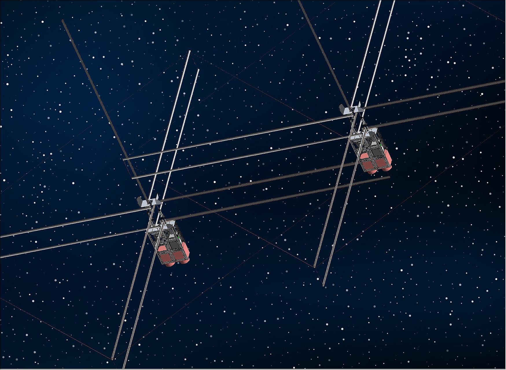
AERO-VISTA’s antennae extend outwards 2 m in five directions from one end of the spacecraft and fits within one unit of payload space (0.1 x 0.1 x 0.1 m) when stowed for launch. To meet launch constraints, the antennae will be deployed with fibreglass “tape measure” technology.
AERO-VISTA (Auroral Emissions Radio Observer-Vector Interferometry Space Technology using AERO)
Overview
In May 2020, NanoAvionics, based in Midland, Texas, received a contract to build two nanosatellites for the Massachusetts Institute of Technology (MIT) AERO-VISTA mission at the NanoAvionics manufacturing facility in Colombia, Illinois, USA. The mission is led by MIT with cooperation from MIT Haystack Observatory, MIT Lincoln Laboratory, Merrimack College, Dartmouth College, and Morehead State University. Funding for the mission is provided by NASA’s Heliophysics Technology and Instrument Development for Science (H-TIDeS) program. 1)
AERO and VISTA are two nanosatellites with the objective to study the nature and sources of radio emission from the ionosphere, observed from a low Earth orbit (LEO). The mission has a 90-day lifetime and is expected to launch in early 2023. The principal investigator of AERO, Dr. Philip Erikson, stated “the aim of the mission is to greatly improve our knowledge of Earth’s aurora by studying its fascinating radio emissions from orbit.” Earth’s aurora has a deep complexity and many unknown features, and is integral for our understanding of space physics. AERO-VISTA will significantly advance our knowledge with observations from the auroral acceleration zone in near-Earth space.1)2)
The principal investigator for VISTA, Dr. Frank Lind, stated "We are very excited about NanoAvionics joining the AERO-VISTA team. Ultimately space science missions are about people exploring our world. It takes a great team of people to make that happen. NanoAvionics is now a key part of our team and we are looking forward to designing and building our satellites with them."
A vector sensor (VS) onboard both AERO and VISTA will measure the amplitude and phase of radio emission in Earth’s aurora zone, a band found between 60 and 75 degrees of latitude. Auroral radiation to be studied by AERO-VISTA includes Auroral Kilometric Radiation (AKR), Medium Frequency Bursts (MFB), and Auroral Roar and Hiss. Satellite operation from a Sun-synchronous polar orbit will allow sensing of radiation not visible from Earth.
The mission will also demonstrate interferometry to create an interference pattern from which source information can be extracted. The result of this experiment will produce higher-resolution data for deeper insight into space-based radio telescope phenomena.
VISTA will complement AERO with an identical twin spacecraft, where together they will provide the first space demonstration of interferometric imaging, beamforming, and nulling using electromagnetic vector sensors (EMVS). With an increased angular resolution, the combined mission will open a gateway of investigation for spatially and temporally complex auroral and solar phenomena. VISTA will complement the scientific return and robustness of the AERO by significantly increasing the quantity and breadth of observations and providing redundancy. 3)
AERO (Auroral Emission Radio Observer) Objectives | VISTA (Vector Interferometry Space Technology using Aero) Objectives |
|---|---|
Characterise auroral radio emissions from Earth’s aurora | Validate algorithms for vector sensor interferometry |
Connect radio emissions to overall auroral geospace system | Apply vector sensor interferometry to auroral radio emissions |
Demonstrate polarimetric high-frequency radio detection with a vector sensor | Perform a survey of the low frequency radio frequency interference (RFI) environment in low Earth orbit (LEO) to assess the suitability of the environment for future interferometric constellations |
Spacecraft
The AERO-VISTA missions will use identical NanoAvionics M6P CubeSat bus and will orbit together using drag control in a 450-600 km, near-polar, noon-midnight Sun-synchronous orbit. The M6P bus is a 6U CubeSat with dimensions 36 x 30 x 10 cm and a mass of 10 kg. The satellites will house identical payloads.3)
AERO-VISTA uses a unique electromagnetic sensor (VS) to study AKR at both low and high frequency ranges (from 100 kHz - 5 MHz), with six orthogonal dipole and loop antennas to provide angle-of-arrival and polarisation information within a single unit. 2)
Observations of auroral radio emissions lead to investigations of nonlinear processes and wave-particle interactions found in heliospheric, planetary and astrophysical plasmas. AERO-VISTA will store compressed observational data onboard and select download segments based on data ground analysis or automatic detection of bright auroral events in the radio spectrum. AERO-VISTA is pathfinder for a high-capability diverse satellite to study radio emissions from the solar corona and inner heliosphere, as well as anisotropic turbulence properties of interplanetary medium plasma.
NanoAvionics’ flagship multi-purpose M6P and M12P are the first preconfigured nanosatellite buses in the sector, designed to serve emerging commercial space markets. The company’s efforts are focused on enabling critical satellite functions and optimising their launch, hardware and operation costs - ranging from single missions to constellations. Its core engineering team has implemented over 75 successful satellite missions and commercial projects during the past several years.
Launch
The AERO-VISTA mission is expected to launch in early 2023.
Orbit: The planned orbit is a sun-synchronous, near-polar orbit, with local solar time (LST) at noon and midnight. The satellites will operate at an altitude of approximately 450 - 600 km.
Mission Status
- April 7, 2021: NASA selected the AERO-VISTA mission to fly as an auxiliary payload with 12 other small research satellites, facilitated by NASA’s Launch Services Program (LSP) and the Educational Launch of Nanosatellites (ELaNa) missions. 9)
- May 7, 2020: NanoAvionics received a contract to build two nanosatellites for the MIT AERO-VISTA mission team at NanoAvionics’ recently opened manufacturing facility in Columbia, Illinois, USA. 10)
The mission is funded by NASA’s Heliophysics Technology and Instrument Development for Science (H-TIDeS) program and led by MIT, with partners including MIT Haystack Observatory, MIT Lincoln Laboratory, Merrimack College, Dartmouth College, and Morehead State University. Morehead State is responsible for bus contracting and ground operations services.
Sensor Complement (EMVS)
EMVS (Electromagnetic Vector Sensor)
The primary payload on both AERO and VISTA is EMVS, a highly sensitive instrument capable of measuring auroral emissions. EMVS measures the six individual components of incident electromagnetic waves ( electric and magnetic fields in three dimensions). It captures the maximum information available at a single point in space, and combined with the use of first and second order signal statistics, enables robust direction finding and imaging capabilities. 4) 5) 6)
The technology demonstration mission aims to validate theoretical sensor performance. In particular, interferometric arrays of vector sensors should maintain noise limited sensitivity even with the presence of terrestrial interference. If validated in flight, low frequency interferometers would not require larger orbits (e.g. lunar orbits), and having a closer communication range would increase the volume of data from space-based radio telescope systems.
The EMVS consists of four subsystems: a deployable antenna; a multi-channel analog receiver; a mixed-signal converter and on-orbit signal processor; and payload memory and data management.
Vector Sensor Antenna
The vector sensor consists of three orthogonal dipoles and three electromagnetic loop antennas that provide angle-of-arrival and polarisation information of signals from 50 kHz to 20 Mhz. To meet launch requirements, the antennas will be deployed with fibreglass “tape measure” technology. The antenna extends outwards 2 m in five directions from one end of the spacecraft and fits within one unit of payload space (0.1 x 0.1 x 0.1 m) when stowed for launch. 3)
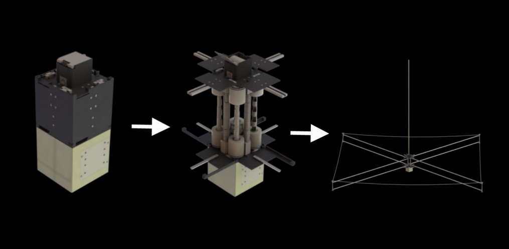
Legend to Figure 3: The stowed payload (left) consists of the antenna deployment canister (black) and the electronics box (gold). First the antenna deployment canister extends upwards (middle), then the antenna doors open and the antenna unspools 2 m in five directions to the deployed configuration (right). The thickness of the antenna perimeter loop is exaggerated for demonstration purposes. 3)
Vector Sensor Radio Receiver (Aurora)
The Aurora software radio is a high performance software radio designed for use in small satellite missions. A large onboard data storage capacity enables radio signal acquisition within the 0.1 to 15 MHz frequency range. The radio system provides on-orbit calibration capabilities, excellent control of both internal and external electromagnetic interference (EMI), and uses a space rated chip scale atomic clock to provide accurate measurements suited for a wide range of scientific observations. 4)
The radio receiver onboard AERO and VISTA amplifies, filters and converts signals from analog to digital with a direct RF (radio frequency) sampling analog-to-digital converter (ADC). This process is followed by initial digital signal processing in a field-programmable gate array (FPGA) processor. 3)
Following initial signal amplification, a noise whitening stage is used to reduce dynamic range requirements of the ADC in order to accommodate the wide range of expected noise. The high sensitivity and low integration time of the antenna and receiver grant AERO and VISTA the ability to capture transient events and meet their science objectives. In-orbit verification of sensitivity, channel-to-channel matching and gain calibration is provided by an absolute reference source in the front end. 3)
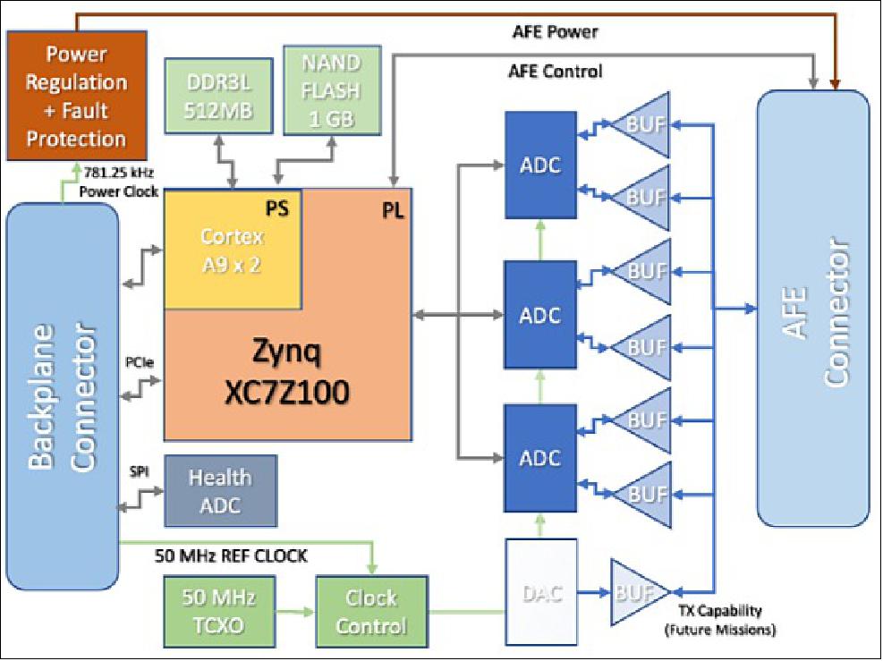
The Aurora software radio is a key element of AERO-VISTA’s scientific payload. It builds on the architecture of the CHREC Space Processor (CSP) with a fully custom implementation 7) that leverages re-configurable computing 8) to enable a flexible software platform 6). In combination with a deployable EVS antenna, this radio is used to implement data acquisition and signal processing for the dual satellite mission. Major architectural components of Aurora are shown in Figure 4.
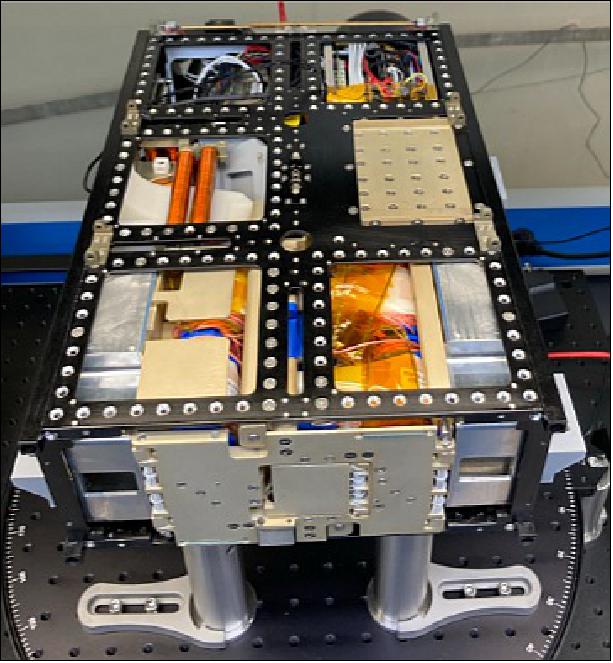
The VS radio receiver consists of: a payload interface processor; vector sensor analog front end (AFE) providing implementation of mission specific RF interfaces; a software radio providing simultaneous six channel data acquisition, redundant NVMe (nonvolatile memory express) solid state storage, and a highly accurate atomic clock providing high stability and low phase noise coherent signals for stable data acquisition. Interferometric imaging requires high stability and simultaneous data capture from multiple spacecraft. 4)
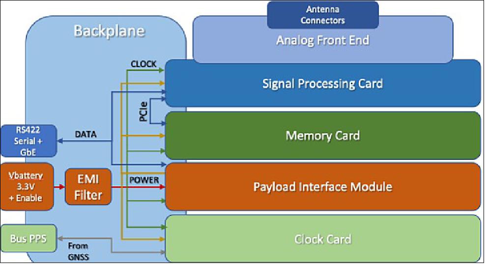
A backplane architecture is used for easier isolation of separate subsystems in testing. The payload interface module houses a secondary processor that provides power regulation, subsystem control, bus command of power state, health and status monitoring, and intelligent fault protection. Aurora interfaces with the satellite bus using a set of connectors integrated into the backplane. These provide access to the bus battery power, a regulated power rail for the supervisory processor, a bus PPS signal, and differential serial and Ethernet data connections. 4)
For the interested reader, more details on the Aurora software radio can be found in Lind et al.’s publication - “Aurora: A Software Radio for Electromagnetic Vector Sensors in Space” (2021). 4)
Mixed Signal Converter
Analog information received by the VS is converted to digital by the signal converter’s first stage and the on-orbit signal processor board. ADC occurs at a maximum rate of 80 MHz, using 16-bit converters with 93 dB spur-free dynamic range. The converters are planned to run at 51.2 MSPS at a maximum analog frequency of 15 MHz. On-orbit signal processing will provide data collection and downlink at either ADC sample rates or with a programmable reduced frequency. The space chip scale atomic clock (CSAC) can be selectively disciplined using the GPS pulse per second (PPS) signal as a configuration parameter. The space CSAC will enable coherent interferometric measurements at low frequencies over desired time scales – from seconds to minutes. 3)
ADC data is handled by an FPGA processor based on the CHREC CSP design modified to include a new Xilinx Zync family chip. Redundant power supply space was used to fit the ACDs onto the CHREC board.
Memory and Data Management
Recorded data is time-tagged with microsecond accuracy provided by the ADC sampling clock and the GPS PPS signal, then stored in payload memory. Data is stored in a solid state M.2 drive mounted on the CHREC sized board in the payload backplane. Data recording, downlink and snapshot requests are provided by software on the Zync signal processor board. Memory redundancy is provided by a second M.2 drive in the payload, with only one drive operational at a time.3)
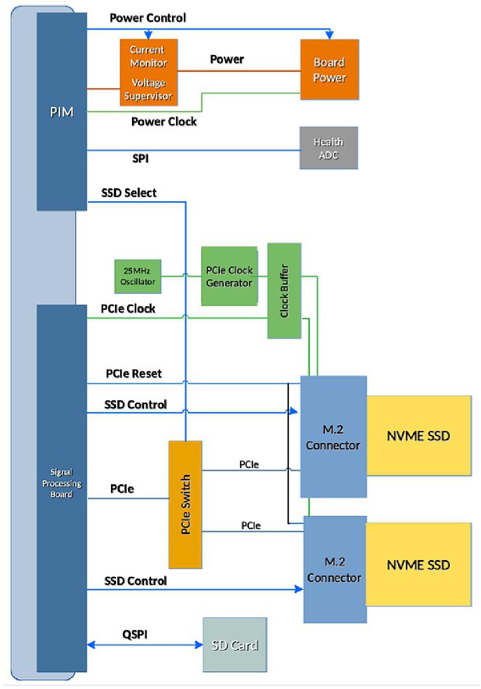
Instrument data is stored within the system’s 2 TB of payload memory. This includes compressed raw samples, 100 ms resolution spectral data, and relevant metadata (timing, attitude, orbital parameters, DC-magnetic field orientation in the spacecraft frame and coarse photometry to detect optical auroral emission), as well as covariance information computed from the 6 signals (3-axis electric field and 3-axis magnetic field) and averaged over 100 msec time resolution. Observational summary data will be downlinked to support science team selection of signals of interest.
RF and Processing | |
|---|---|
Sensing Elements (VS Antenna) | |
Magnetic field | 3 Crossed Loops |
Electric field | 2 Dipoles, 1 Monopole |
Receiver | |
Number of Channels | 6 simultaneous sampled |
Attenuation Range | 0 to 31 dB |
Attenuation Step | 0.5 dB |
Max Input Power | +33 dBm |
SFDR (1 MHz tone) | 77 dB |
ADC Resolution | 16 bit |
Sample Rate | 50 MSPS |
Analog Bandwidth | 0.1 to 15 MHz |
Data Products | Raw ADC, Downsampled IQ, Spectrogram, Covariance |
Processing System | |
Processor Unit | Zynq 7100 |
Storage | 2 x 1 TB redundant NVMe SSD |
Timing System | Space Chip Scale Atomic Clock |
Timing Accuracy | <65 nanosec sample alignment, <2E-11 ADEV @ 100 sec |
Other Specifications | |
Power | |
Battery Rail | 6.5 to 15 V @ 3A max |
Supervisor Rail | 3.3V @ 0.5A max |
Power Consumption | 18 to 20W |
Interfaces | |
10/100/1000 Ethernet | RS422 UART , JTAG |
Physical | |
Dimensions | 92.4 x 96.7 x 104.6 mm |
Mass | 1.2 kg |
Environmental | |
Operating Temperature | -20 to 45ºC |
Storage Temperature | -40 to 85ºC |
Ground Segment
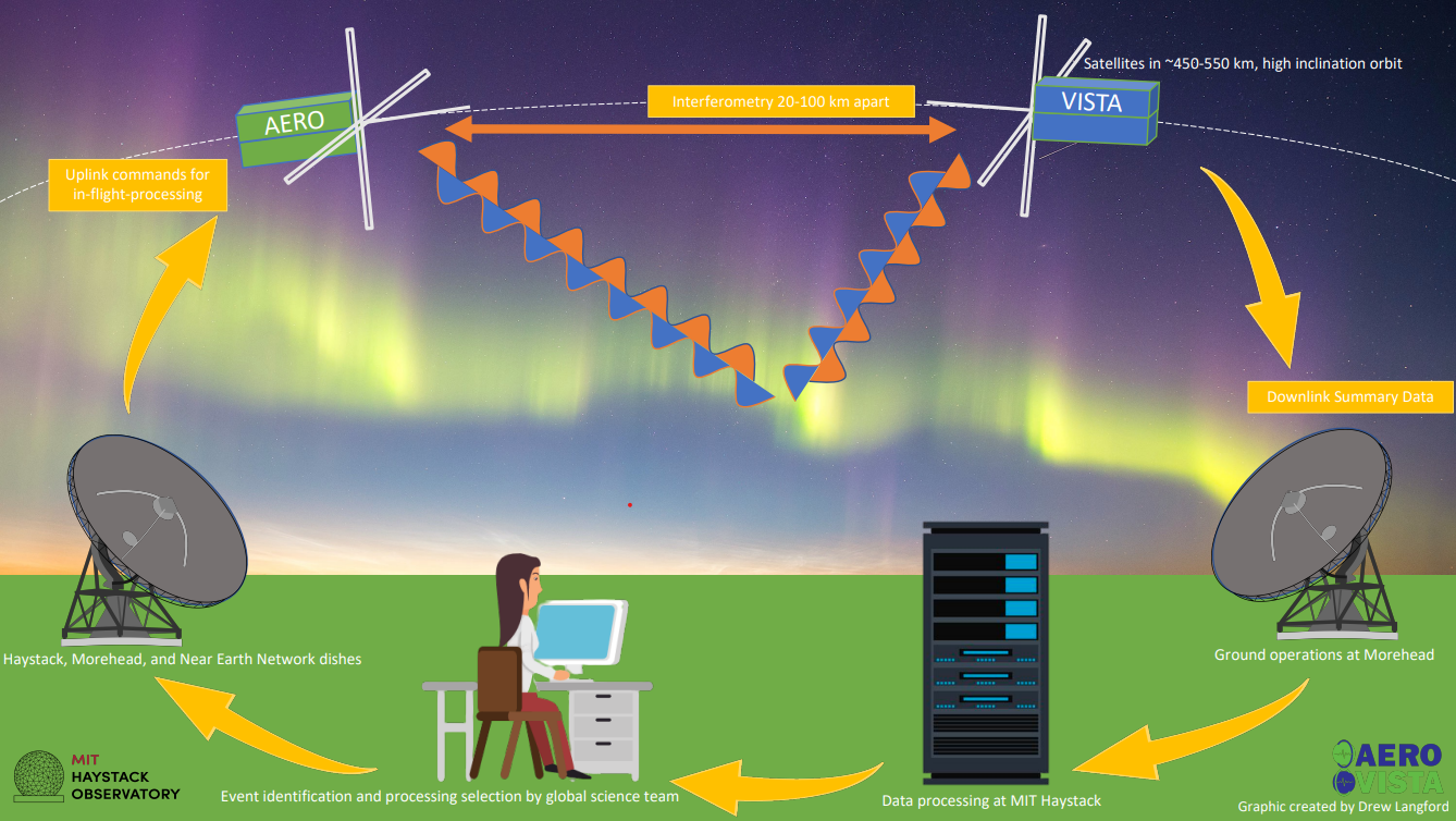
AERO-VISTA ground operations process is as follows (see Figure 9):
- AERO and VISTA simultaneously gather auroral radiation data with the EMVS onboard each spacecraft.
- RF spectrogram and metadata summary data files are downlinked through dishes at both Morehead State University and MIT Haystack Observatory.
- Summary data is processed through pipelines hosted at MIT Haystack facilities.
- AERO-VISTA team scientists use the AVIS (AERO-VISTA Interactive Spectrogram) Display for event identification and make commands for in-orbit processing.
- AVIS Display commands are integrated into spacecraft uplink commands.
- Dishes at Morehead State University (MSU), MIT Haystack and NASA NEN (Near Earth Network) uplink commands for data management and in-orbit processing.
The twin EMVS payloads onboard AERO and VISTA will capture hundreds of gigabytes of data every day whilst performing independent and joint observations of auroral phenomena such as AKR. With limited downlink opportunities with each spacecraft pass, the mission requires a tool to aid scientific processing and downlink decisions. The AVIS Display, a project developed at MIT Haystack Observatory, consists of a dynamic user interface for users to perform preliminary data analysis and selection. Data analysis tools including channel selectors, data scaling, and axis sliders allow scientists to filter data for further investigation. A variable resolution selection tool allows selection of auroral phenomena viewed in the spectrogram. Standard exportation procedures are integrated into the system for uplink of in-orbit processing of data. 10)
References
1) ”Satellites for NASA funded AERO-VISTA mission to be built by NanoAvionics,” Space Daily, 8 May 2020, URL: https://www.spacedaily.com/reports/Satellites_for_NASA_funded_AERO_VISTA_mission_to_be_built_by_NanoAvionics_999.html
2) ”AERO-VISTA CubeSat Mission,” MIT Haystack, 2022, URL: https://www.haystack.mit.edu/geospace/geospace-projects/aero-vista-cubesat-mission/
3) Frank D. Lind, Philip J. Erickson, Michael Hecht, Mary Knapp, Geoffrey Crew, Ryan Volz, John Swoboda, Frank Robey, Mark Silver, Alan J. Fenn, Benjamin Malphrus, Kerri Cahoy, ”AERO & VISTA: Demonstrating HF Radio Interferometry with Vector Sensors,” Proceedings of the 33rd Annual AIAA/USU Conference on Small Satellites, August 3-8, 2019, Logan, UT, USA, paper: SSC19-WKV-09, URL: https://digitalcommons.usu.edu/cgi/viewcontent.cgi?article=4395&context=smallsat
4) Frank Lind, Mary Knapp, Phil Erickson, Russ McWhirter, Robert Schaefer, Tobias Gedenk, Frank Robey, Erik Thompson, Mark Silver, Alan Fenn, Janusz Majewski, Alexander Morris, Wayne Boland, Frank Schiavone, Rebecca Masterson, Nicholas Belsten, Alvar Saenz Otero, ”Aurora: A Software Radio for Electromagnetic Vector Sensors in Space,” Proceedings of the 36th Annual AIAA/USU Virtual Conference on Small Satellites, August 6-11, 2021, Logan, UT, USA, Paper: SSC22-III-01, URL: https://digitalcommons.usu.edu/cgi/viewcontent.cgi?article=5309&context=smallsat
5) Arye Nehorai and Eytan Paldi. ”Vector-sensor array processing for electromagnetic source localization,” IEEE transactions on signal processing, Volume 42 Issue 2, pp:376–398, February 1994, URL: https://ieeexplore.ieee.org/document/275610
6) Ryan Volz, Mary Knapp, Frank D Lind, and Frank C Robey. ”Covariance estimation in terms of stokes parameters with application to vector sensor imaging,” Published in: 2016 50th Asilomar Conference on Signals, Systems and Computers, pp: 1339-1343, IEEE Xplore, https://ieeexplore.ieee.org/document/7869593, URL: https://apps.dtic.mil/sti/pdfs/AD1030386.pdf
7) Dylan Rudolph, Christopher Wilson, Jacob, Stewart, Patrick Gauvin, Alan George, Herman Lam, Gary Crum, Mike Wirthlin, Alex Wilson, and Aaron Stoddard, ”Csp: A multifaceted hybrid architecture for space computing,”2 August 2014, paper: SSC14-III-3, URL: https://ntrs.nasa.gov/citations/20150000168
8) Alan D George and Christopher M Wilson, ”Onboard processing with hybrid and reconfigurable computing on small satellites,” Proceedings of the IEEE, Volume106, Issue 3, pp:458–470, March2018, URL: https://ieeexplore.ieee.org/document/8303008
9) “NASA Announces 12th Round of Candidates for CubeSat Space Missions,” NASA, 2021, URL: https://www.nasa.gov/feature/nasa-announces-12th-round-of-candidates-for-cubesat-space-missions
10) Andrew Langford, Mary Knapp, John Swoboda, Ryan Volz, Phil Erickson, Frank Lind, “The AERO-VISTA Interactive Spectrogram Display: An Original Software Solution for Scientific Operations of Twin 6U CubeSats,” Proceedings of the 35th Annual Small Satellites Conference, 2021, Logan, UT, USA, Paper: SSC21-V-01 , URL: https://digitalcommons.usu.edu/cgi/viewcontent.cgi?article=5038&context=smallsat