ALEXIS (Array of Low-Energy X-Ray Imaging Sensors)
EO
Mission complete
LANL
Quick facts
Overview
| Mission type | EO |
| Agency | LANL |
| Mission status | Mission complete |
| Launch date | 25 Apr 1993 |
| End of life date | 29 Apr 2005 |
| CEOS EO Handbook | See ALEXIS (Array of Low-Energy X-Ray Imaging Sensors) summary |
ALEXIS (Array of Low-Energy X-Ray Imaging Sensors)
ALEXIS is a sophisticated US microsatellite technology demonstration mission of Los Alamos National Laboratory (LANL), Los Alamos, New Mexico, funded by DOE (Department of Energy) and built by Comtech AA (AeroAstro Inc.), Ashburn, VA. Sandia National Laboratory, UCB/SSL (UC Berkeley/Space Sciences Laboratory) are partners of LANL in the mission. 1)
Spacecraft
The S/C bus is a complex, robust, and flexible structure comprised of communications, power, and control subsystems. The bus processor comprises redundant 80C86-based CPUs and six on-board mass memory boards with 96 MByte (SRAM) total storage capacity. This bus assembly occupies less than 25% of the S/C volume with a mass of 45 kg.
The S/C is spin-stabilized and uses solar pointing for orientation (fine and coarse sun sensors) and magnetic torque coils for attitude reconstitution. The bus points the payload in the anti-sun direction and rotates once per about 50 seconds about that sun-line. Sun sensors and a limb sensor provide attitude knowledge of 0.1º. Attitude is controlled using magnetic torque coils. 2)
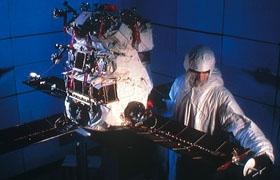
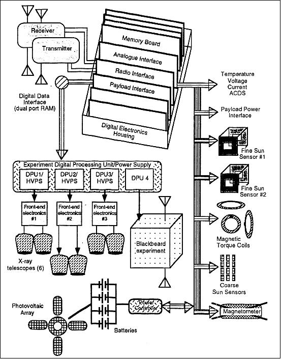
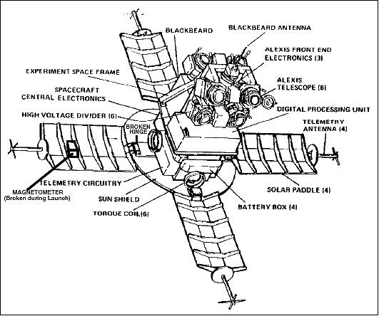
Total S/C mass = 113 kg, power = 50 W. Power is produced by four deployable solar panels and a fifth fixed disk which also serves as a sun shield. Power is distributed to four 1.2 Ah NiCd 28 V batteries.
RF communications: S-band data transmission (uplink/downlink). Downlink data rate = 750 kbit/s, uplink data rate = 9.6 kbit/s. A single ground station (1.8 m dish) is located at LANL, Los Alamos, NM.
Orbit: Apogee = 844 km, perigee = 749 km, inclination = 70º.
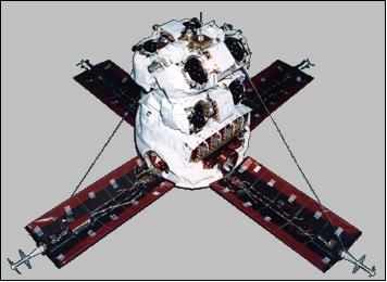
Launch
The spacecraft was launched by a Pegasus air-launched booster (of OSC) on April 25, 1993. During powered flight a solar paddle was damaged; initial attempts to contact ALEXIS were unsuccessful. A deployment hinge bracket failed on the +Y paddle. This left the paddle attached to the spacecraft only by a flexible piece of harness (a bundle of wires) and a restraining cable. The launch damage left a solar array paddle free to flap under the influence of thermal inputs, which causes spin rate and direction changes.
As a consequence, an attitude reconstruction algorithm was developed and tested for the ALEXIS spacecraft. It takes inputs from a fine sun sensor and a horizon crossing indicator and processes them using a square-root-information filter/smoother. The filter/smoother model includes Euler dynamics and random-walk torques to approximate thermal/flexible effects. 3)
The satellite responded in June 1993 and soon was brought under control. By late July 1993, full satellite operations had been restored through implementation of new procedures for attitude control. S/C operations are performed from LANL. 4) 5) 6)
Mission Status
• The spacecraft, launched in April 1993, operated for almost 12 years before being decommissioned on April 29, 2005. The design life of one year has been exceeded by far (Ref. 2). 7) 8) 9)
• In August 2003, the ALEXIS satellite had successfully completed its 10th year of on-orbit science operations. 10)
• Up to 1999 the ALEXIS mission was operating nominally, it exceeded all expectations in spite of the serious launch incident with the solar panel array. A completely new software system (on the ground) was in place to calculate S/C attitude, critical to the on-board operation of the X-ray telescopes. Over 80 GByte of of mission data have been received thus far. 11) 12) 13) 14)
• Dual-ported RAM failures in the fall of 1999 have resulted in data only available from telescope pairs #1 & #2 and from the Blackbeard experiment. Data quality in the telescopes has been degrading as solar maximum approached due to increased particle backgrounds.
• In April 1998, the ALEXIS spacecraft marked its 5th year on orbit. A key to ALEXIS' durability has been the innovative, low-power bus design provided by AeroAstro and the company's innovations in the telemetry system, which made ALEXIS a simpler spacecraft to operate. 15)
• By late July 1993, full satellite operations had been restored through the implementation of new procedures for attitude control. Science operations with the two onboard experiments began at that time.
• ALEXIS had a rocky beginning. One of the satellite's solar panels tore free of its hinge attachment during launch; a subsequent analysis showed the hinge had probably been damaged during ground testing, and launch vibrations were the last straw. Only electrical cables and a guide wire kept the panel attached. As a result of the damaged solar panels, the spacecraft contracted some wobble -which reduced the precise attitude information. 16)
Sensor Complement
ALEXIS (Array of Low Energy X-ray Imaging Sensors)
The instrument has the same name as the S/C. The ALEXIS telescope system is comprised of a DPU (Data Processing Unit which provides the switched and conditioned low voltage power and high voltage power for the ALEXIS telescopes, command decoding, distribution and all onboard data processing, FEE (Front End Electronics) which does the pulse digitizing and initial processing, and the telescopes containing mirrors, filters and microchannel plate detectors.
Alexis is an outward-looking instrument for the detection of astrophysical signals. The instrument is an ultrasoft X-ray monitor, consisting of six compact normal-incidence telescopes tuned to narrow bands centered on 66, 71 and 93 eV. The 66 and 71 eV bandpasses are centered on a cluster of emission lines from Fe IX-XII. The 93 eV band, although designed as a continuum channel, includes Fe XXIII line characteristics of 107 K plasma.
The six ALEXIS EUV (Extreme Ultraviolet) telescopes are arranged in pairs covering three overlapping 33º FOVs. During each 45 second spin of the S/C, ALEXIS monitors the entire antisolar hemisphere. Each telescope consists of a spherical mirror with a Mo-Si layered synthetic microstructure (LSM) or multilayer coating, a curved profile microchannel plate detector located at the telescope's prime focus, a UV background-rejecting filter, electron rejecting magnets at the telescope aperture, and image processing readout electronics.
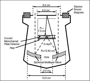
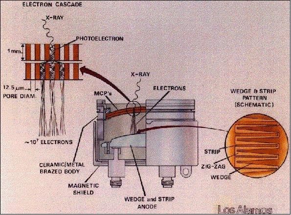
The geometric collecting area of each telescope is about 25 cm2, with spherical aberration-limiting resolution to about 0.25º s. The resolution of each telescope is limited to about 0.5º diameter. The ALEXIS detectors are double plate, curved front faced, microchannel plates (MCP) paired with wedge and strip-resistive anodes. The two MCPs, of 46 mm in diameter, are single photon imaging detectors, each with 12.5 µm diameter channels.
Telescope ID | Filter type | Photocathode | Bandpass center |
1A | Lexan/Titanium/Boron | MgF2 | 93 eV (130 Å) |
1B | Aluminum(Silicon)/Carbon | NaBr | 71 eV (172 Å) |
2A | Lexan/Titanium/Boron | MgF2 | 93 eV (130 Å) |
2B | Aluminum(Silicon)/Carbon | NaBr | 66 eV (186 Å) |
3A | Aluminum(Silicon)/Carbon | NaBr | 71 eV (172 Å) |
3B | Aluminum(Silicon)/Carbon | NaBr | 66 eV (186 Å) |
The mass of the ALEXIS instrument is 45 kg, power = 45 W; the average data rate is 10 kbit/s of event data. Position and time of arrival are recorded for each event (detected photon, etc.). Measurement objectives: mapping the diffuse background in three bands, performing a narrow-band survey of point sources, searching for transient phenomena, and monitoring variable ultrasoft X-ray sources. 17) 18)
Blackbeard
The ALEXIS payload consists of an ultrasoft X-ray telescope array and a high-speed VHF receiver/digitizer with the name of Blackbeard. This payload is designed to make radio frequency observations in the VHF band. It consists principally of two selectable monopole antennas, a band-selectable receiver, and a broadband (150 MS/s) digitizer. Other components of the payload include narrowband channels, a broadband trigger circuit, and two simple photodiode arrays.
The instrument looks at signals emitted near the Earth. Blackbeard is a radio frequency (RF) experiment with the objective to study distortion and interference effects on transient transionospheric VHF signals, such as lighting and artificial pulses. The instrument senses perturbations to the ionosphere; it can make a distinction between multipath distortions resulting from large-scale coherent perturbations and from small-scale random perturbations to the ionosphere. The specific experiments of Blackbeard include:
- Broadband VHF measurements of transient signals originating from a controlled pulsed ground beacon, to characterize broadband ionospheric distortion.
- Narrowband VHF measurements of CW-signals from a multichord interferometry ground beacon array, to characterize the ionospheric structure contributing to transmission distortion.
- Surveying power envelopes of lightning and man-made interference in selectable VHF bands, for background rejection purposes.
Blackbeard operation consists of on-board 150 MHz digitization for 0.1 s in a broadband reception mode; or 50 kHz digitization for 320 s in a narrow-band reception mode; or 120 kHz effective digitization for 130 s in a power-envelope survey mode. - The broadband mode has selectable bandwidths up to 65 MHz within the ranges 25-100 MHz and 100-175 MHz, with a maximum of 30 dB SNR. The narrow-band mode has eight selectable 4 kHz bands between 32 and 36 MHz, with a maximum 40 dB SNR and 0.1 Hz Doppler resolution. Mixed-mode operation is available in which broadband and narrowband data are collected to allow correlated RF distortion and ionospheric structure analysis.
The Blackbeard instrument observed strange radio bursts called TIPPs (Trans-Ionospheric Pulse Pairs). These strange signals are the most intense radio sources from Earth which can be much stronger than typical lightning. Then in 1996, LANL researches reported the first simultaneous Blackbeard observations and multiple ground station measurements of TIPPs. The new evidence suggests that TIPPs come from thunderstorms and probably comprise an atmospheric event and its reflections off Earth. 19) 20) 21)
References
1) W. Priedhorsky, B. W. Smith, J. J. Bloch, D. H. Holden, D. C. A. Roussel-Dupré, R. Dingler, R. Warner, G. Huffman, R. Miller, B. Dill, R. Fleeter, “The ALEXIS Small Satellite Project: Initial Flight Results,” AIAA Space Programs and Technologies Conference, Sept. 21-23, 1993, Huntsville, AL, USA; and Proc. SPIE Vol. 2006, 1993, pp. 114-126
2) https://web.archive.org/web/20120820130353/http://www.aeroastro.com/index.php/program-heritage/alexis
3) Mark L. Psiaki, James Theiler, Jeffrey Bloch, Sean Ryan, Robert W. Dill, Richard E. Warner, “ALEXIS Spacecraft Attitude Reconstruction with Thermal/Flexible Motions due to Launch Damage,” Journal of Guidance , Control and Dynamics, Vol. 20, No 5, September-October 1997, AIAA paper No 97-3617, URL: http://www.mae.cornell.edu/psiaki/alexis01.pdf
4) D. Roussel-Dupre, J. J. Bloch, et al., “ALEXIS - the six Year Telescope Flight Experience,” SPIE, Vol. 3764-34, 1999
5) D. Roussel-Dupre, J. Bloch, C. Little, R. Dingler, B. Dunne, S. Fletcher, M. Kennison, K. Ramsey, R. King, J. Theiler, J. Sutton, J. Wren, “ALEXIS, the Little Satellite That Could - 4 Years Later,” Proceedings of the 11th AIAA/USU Conference on Small Satellites, Sept. 15-18, 1997, Logan, UT, SSC97-IV-3
6) J. Bloch, T. Armstrong, B. Dingler, D. Enemark, D. Holden, C. Little, C. Munson, B. Priedhorsky, D. Roussel-Dupré, B. Smith, “The ALEXIS mission recovery,” Proceedings of the 17th Annual American Astronomical Society (AAS) Guidance and Control Conference, Keystone, CO, Feb. 2-6, 1994
7) “Lab's ALEXIS satellite completes its mission,” Los Alamos Newsletter, Vol. 7, No 1, Jan. 2, 2006, p. 3, URL: http://www.lanl.gov/news/newsletter/010206.pdf
8) http://imagine.gsfc.nasa.gov/docs/sats_n_data/missions/alexis.html
9) “ALEXIS Retires after a 12-Year Career On Orbit,” Comtech AeroAstro, May 5, 2005, URL: [web source no longer available]
10) “ALEXIS Celebrates 10 Years of Successful On-Orbit Operations,” Space Daily, Aug. 11, 2003, URL: http://www.spacedaily.com/news/microsat-03j.html
11) Information provided by J. Bloch of LANL, Los Alamos, NM
12) “ALEXIS satellite marks fifth anniversary of launch,” LANL News Bulletin, April 23, 1998, URL: http://www.lanl.gov/orgs/pa/News/042398.html
13) Jeffrey J. Bloch, Diane Roussel-Dupre, Scott Starin, “Flight performance of UV filters on the ALEXIS satellite,” URL: http://www.osti.gov/bridge/servlets/purl/758957-YrcGVE/webviewable/
14) Diane Roussel-Dupr e, Jeffrey J. Bloch, Elsa M. Johnson, James Theiler, “ALEXIS-the Six Year Telescope Flight Experience,” SPIE, Vol. 3765,, 1999, URL: http://library.lanl.gov/cgi-bin/getfile?00796015.pdf
15) ALEXIS satellite marks fifth anniversary of launch, LANL, April 23, 1998, URL: http://www.lanl.gov/news/releases/archive/98-062.shtml
16) Jeff Bloch,Tom Armstrong, Bob Dingler, Don Enemark, Dan Holden, Cindy Little, Carter Munson, Bill Priedhorsky, Diane Roussel-Dupre,, Barham Smith,Richard Warner, Bob Dill, Greg Huffman,Frank McLoughlin, Raymond Mills, Robert Miller, “The ALEXIS Mission Recovery,” 1994, URL: http://www.osti.gov/bridge/servlets/purl/142518-yiLBJP/native/142518.pdf
17) W. C. Priedhorsky, J. J. Bloch, S. P. Wallin, W. T. Armstrong, O. H. W. Siegmund, J. Griffee, R. Fleeter, “The ALEXIS Small Satellite Project: Better, Faster, Cheaper Faces Reality,” IEEE Transactions on Nuclear Science, Vol. 40, No. 4, August 4, 1993, pp. 863-873
18) J. J. Bloch, et al., “Design, Performance and Calibration of the ALEXIS Ultrasoft X-Ray Telescopes,” SPIE, Vol. 1344, 1990 , pp. 154-165
19) Dateline: Los Alamos, Current Missions, “ALEXIS: The Little Satellite That Could,” Jan./Feb./Mar. issue 1998, pp. 12-14
20) D. Roussel-Dupre, J. J. Bloch, E. M. Johnson, J. Theiler, “ALEXIS-the Six Year Telescope Flight Experience,” Proceedings of SPIE, Vol. 3765, 1999 pp. 329-340, `EUV, X-Ray, and Gamma-Ray Instrumentation for Astronomy X,' Oswald H. Siegmund; Kathryn A. Flanagan; Eds.
21) David A. Smith, Dorothea M. DeLapp, Daniel N. Holden, Gary L. Stelzer, Phillip L. Klinge, “Calibration and Evaluation of Blackbeard Time Tagging Capability,” 11 th Annual AIAA/USU Conference on Small Satellites, September 15-1 8, 1997, Logan, Utah, URL: http://www.osti.gov/bridge/servlets/purl/555547-3TNQwx/webviewable/555547.pdf
The information compiled and edited in this article was provided by Herbert J. Kramer from his documentation of: ”Observation of the Earth and Its Environment: Survey of Missions and Sensors” (Springer Verlag) as well as many other sources after the publication of the 4th edition in 2002. - Comments and corrections to this article are always welcome for further updates (eoportal@symbios.space).