ALOS (Advanced Land Observing Satellite) / Daichi
EO
JAXA
Ocean
Multi-purpose imagery (ocean)
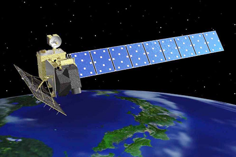
Launched in January 2006 and decommissioned in April 2011, ALOS (Advanced Land Observing Satellite), also known as Daichi, was a Japanese Earth observation mission. Developed by JAXA (Japan Aerospace Exploration Agency), the mission's objectives called for high-resolution microwave imagery, for applications in cartographic mapping, regional observation, disaster monitoring and resource surveying.
Quick facts
Overview
| Mission type | EO |
| Agency | JAXA |
| Mission status | Mission complete |
| Launch date | 24 Jan 2006 |
| End of life date | 22 Apr 2011 |
| Measurement domain | Ocean, Land, Snow & Ice |
| Measurement category | Multi-purpose imagery (ocean), Multi-purpose imagery (land), Vegetation, Albedo and reflectance, Landscape topography, Sea ice cover, edge and thickness, Soil moisture, Snow cover, edge and depth, Ocean surface winds, Ice sheet topography |
| Measurement detailed | Ocean imagery and water leaving spectral radiance, Land surface imagery, Vegetation type, Fire fractional cover, Earth surface albedo, Land cover, Land surface topography, Wind vector over sea surface (horizontal), Sea-ice cover, Snow cover, Soil moisture at the surface, Normalized Differential Vegetation Index (NDVI), Iceberg fractional cover, Iceberg height, Sea-ice type, Glacier motion, Sea-ice sheet topography, Above Ground Biomass (AGB), Snow melting status (wet/dry) |
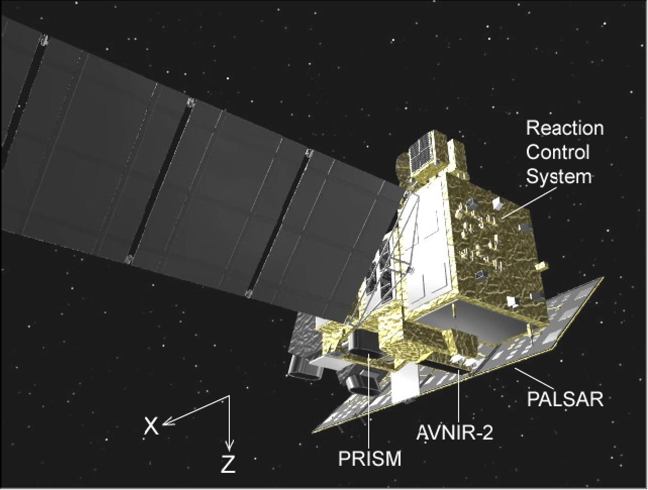
| Instruments | PALSAR, AVNIR-2, PRISM |
| Instrument type | High resolution optical imagers, Imaging microwave radars |
| CEOS EO Handbook | See ALOS (Advanced Land Observing Satellite) / Daichi summary |
Related Resources
Summary
Mission Capabilities
ALOS carried three instruments, PRISM (Panchromatic Remote-sensing Instrument for Stereo Mapping), AVNIR-2 (Advanced Visible and Near Infrared Radiometer 2) and PALSAR (Phased Array L-band Synthetic Aperture Radar). PRISM was a panchromatic radiometer that aimed to collect high-resolution stereo data for cartographic applications, while AVNIR-2 was a multispectral optical imager that aimed to monitor regional environmental land coverage and land use. PALSAR was a Synthetic Aperture Radar (SAR) instrument capable of dual-polarisation, with applications in resource exploration and environmental protection.
Performance Specifications
PRISM utilised a pushbroom scanning technique and covered a spectral range of 0.52-0.77 µm with a swath width of 35 km for triplet stereo observation and 70 km for nadir observations. The instrument had a field of view (FOV) of greater than 7.6° and a spatial resolution of 2.5 m. AVNIR-2 covered 4 spectral bands, with a spectral range of 0.42 µm - 0.89 µm. It had a swath width of 70 km, with a FOV of 5.8°, and a spatial resolution of 10 m. PALSAR operated in 4 different imaging modes, Fine Beam (High resolution), Direct downlink, ScanSAR, and Polarimetry mode. Across these modes, spatial resolution ranges from 7 m (FineBeam) to 154 m (ScanSAR), while swath width ranges from 30 km (Polarimetry mode) to 360 km (ScanSAR).
ALOS operated in a near-recursive sun-synchronous orbit of altitude 692 km, inclination 98.16 and orbit LST (Local Solar Time) of 1030 hours. It had an orbital period of 98.7 minutes and a repeat cycle of 46 days.
Space and Hardware Components
The ALOS bus consisted of CFRP Carbon Fibre Reinforced Plastic (CFRP) trusses, with aluminium fittings, and had a launch mass of approximately 4000 kg. The spacecraft, when stowed, has dimensions 6.4 m x 3.4 m x 4.3 m, while in its orbital configuration it has dimensions 8.9 m x 27.4 m x 6.2 m. Its Attitude and Orbital Control (AOCS) subsystem consisted of three star trackers, an Inertial Reference Unit (IRU), an Earth Sensor Assembly (ESA) and a high performance onboard computer, Attitude and Orbit Control Electronics (AOCE), as well as a precision GPS receiver. In terms of Radio Frequency (RF) communications, the primary data transmission link was transmitted in Ka-band at a rate of 240 Mbit/s, while Tracking, Telemetry and Command (TT&C) was communicated in S-band. ALOS was equipped with a solid state recorder, allowing onboard data storage of 768 Gbit. ALOS also carried RRA (Retro-Reflector Array), an instrument that provided support for precise orbit determination.
ALOS (Advanced Land Observing Satellite) / Daichi
Spacecraft Launch Mission Status Sensor Complement Ground Segment References
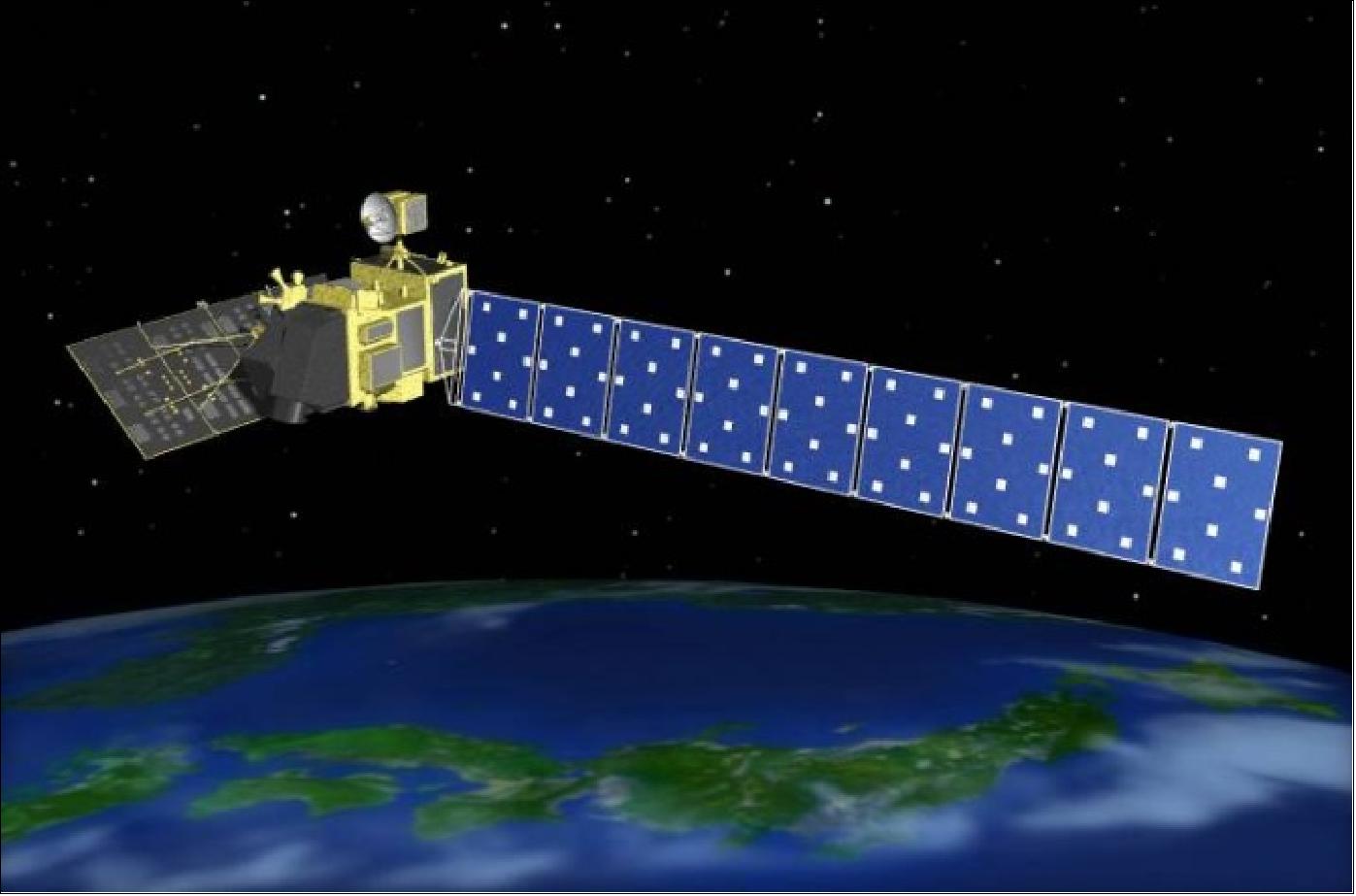
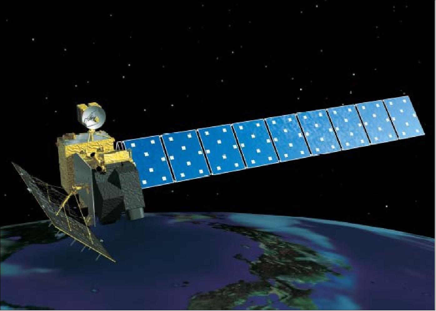
ALOS (nicknamed ”Daichi”) is a Japanese Earth-observation satellite, developed by JAXA (Japan Aerospace Exploration Agency, Tokyo; formerly NASDA), and manufactured by NEC, Toshiba, and Mitsubishi Electric Corp. The objectives call for an optical and an active microwave sensor payload who's high-resolution data may be used for such applications as cartographic mapping, environmental and hazard monitoring (within 48 hours). The intent is to provide the user community with data of sufficient resolution to be able to generate 1:25,000 scale maps. This in turn requires observational data of 2.5 m horizontal resolution for the determination of land conditions, and a 3-5 m vertical accuracy for contour mapping. Multispectral data with 10 m horizontal resolution is needed for the classification of land cover (vegetation, forests, etc.). Short-term hazard monitoring (within 24 hours on average) will be accommodated by the use of pointing mechanisms. Particular application features of the ALOS mission are: 1) 2) 3)
• The mapping of land areas (without the need for ground control points) for cartographic applications
• The monitoring of disasters on a global scale (as a complement to the capabilities of other spacecraft) 4)
Spacecraft
The S/C structure consists of CFRP (Carbon Fiber Reinforced Plastic) trusses and aluminum fittings. The approximate S/C dimensions in the stowed configuration are: 6.4 m x 3.4 m x 4.3 m (x, y, z); the in-orbit configuration dimensions are: 8.9 m x 27.4 m x 6.2 m (x, y, z, where x is in the velocity direction and z is toward nadir).
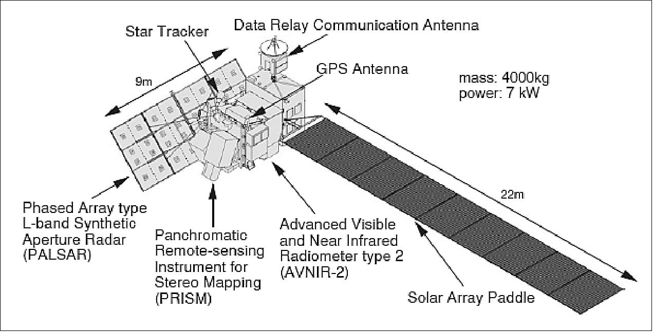
The S/C mass is about 4000 kg (at lift-off, 180 kg of hydrazine), the largest satellite ever for Japan. Its solar array (size 22 m x 3 m) generates power of 7 kW (EOL). ALOS has five sets of NiCd type battery (BAT). On orbit, a paddle drive rotates the solar array into the sun for maximum efficiency. A combination of active/passive thermal control subsystem is used. The spacecraft design life is 3 years with a goal of 5 years.
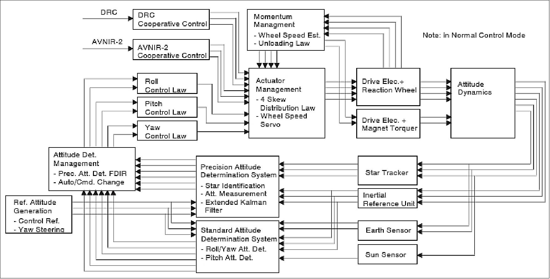
AOCS (Attitude Orbit and Control System): The ALOS S/C requires in particular precise attitude and position determination to minimize image quality degradation. The AOCS is based on the 3 axis strap-down attitude determination and zero momentum attitude control. The AOCS hardware and software are integrated to constitute the closed loop system (Figure 2). The AOCS introduces the following new components: 1) precision Star Tracker, 2) precision GPS Receiver capable of dual-frequency carrier phase measurement, and 3) a high-performance onboard computer, AOCE (Attitude & Orbit Control Electronics), based on new 64-bit spaceborne MPUs (Microprocessor Chips).
Attitude is sensed by the following devices: STT (Star Tracker) triplet configuration, IRU (Inertial Reference Unit), ESA (Earth Sensor Assembly), and carrier phase tracking of a GPS receiver (dual frequency). In addition, a laser corner-cube reflector is being used for SLR tracking services to calibrate the GPS receiver. The actuators used are: reaction wheels, magnetic torque rods and 16 hydrazine thrusters of RCS (Reaction Control Subsystem), each with a thrust of 1 N. A short-term attitude stability of ±0.00002º/0.37 ms (3σ) is provided; the long-term stability is ±0.0002º/5 s (3σ). The pointing accuracy knowledge is ±0.0002º, and the spacecraft position accuracy knowledge is ±1.0 m (a posteriori). The dual-frequency carrier-phase tracking GPS receiver of Toshiba Corp. is used for orbit determination. 5) 6) 7)
STT (Star Tracker). The ALOS STT is a key element in achieving required attitude determination accuracy. It is a precision fixed-head attitude sensor with a CCD detector design. STT has 3 optical heads (STO) and uses 2 optical heads simultaneously. It detects positions and the brightness of stars in its two fields of view (FOV), calculates corresponding addresses and intensity levels of the stars in its star tracker coordinate frame, and provides the results to the AOCE. 8) 9) 10)
Configuration | 3 STOs and STAEs (STT Analog Electronic units)) - 3 on but 2 in operation; | |
FOV | 8º x 8º | |
Star sensitivity range | 4 ~6.5 magnitude | |
No of stars observed | 10 x 2 (acquisition), 5 x 2 (tracking) | |
Star position accuracy | Random | 3.1 arcsec (4 mag), 9 arcsec (6 mag); 13.7 arcsec (6.5 mag) |
Star position accuracy | Random | 20 arcsec (4~6.6 mag) |
Star intensity accuracy | Random | -0.26 ~ +0.28 mag ((@ 6 mag) |
Accuracy assured rate | 0.0608 ± 0.0008º/s (H); 0.005º/s (V) | |
Maximum tracking rate | 0.1º/s | |
Maximum acquisition rate | 0.1º/s | |
Timing accuracy | ±1 µs | |
Update rate | 1 Hz | |
Head switch-over time | 3 s | |
Exclusion angles | ±35º (sun), ±25º (S/C secondary reflection) | |
Instrument mass | 39.8 kg (for 3 STO configuration) | |
Power consumption | 150.4 W (for 3 STO configuration) | |
Approach | Zero momentum control with 3-axis strapdown attitude determination |
Operational modes | Standby, Acquisition, Orbit Control, Normal Control (Standard, Precision) |
Attitude control accuracy | R (roll), P (pitch), Y (yaw): ± 0.095º (3 σ) |
Attitude stability, short term | R, Y: 1.9 x 10⁻⁵ º/ 0.37 ms; P: 0.95 x 10⁻⁵ º/0.37 ms |
Attitude stability, long term | R, P. Y: 1.9 x 10⁻⁴ º/5 s; with DRC (Data Relay Communication) antenna not in drive |
Attitude determination accuracy | R, P, Y: ±3. 0º x 10-4 (3 σ), onboard |
Position determination accuracy | 200 m (95%), onboard |
Data output | STT (Precision Star Tracker), GPSR (GPS Receiver), & IRU (Inertial Reference Unit) data |
Other features | Yaw steering, paddle control |
Control cycle | 10 Hz |
STT position accuracy | Random error: 9.0 arcsec for a star of magnitude 6 |
STT (3 available, 2 in operation) | FOV = 8º x 8º; output rate of 1 Hz |
DMS (Data Management System) | Onboard data bus: MIL-STD-1553B, all data handling uses CCSDS protocols |
The precision GPSR (GPS Receiver) is a key component to the position determination requirements of ALOS. JAXA developed developed the dual-frequency spaceborne GPS receiver that provides carrier phase measurement. GPSR measures pseudoranges and carrier phases of both L1 and L2 signals. The pseudorange of the L1 signal is used for the onboard, stand-alone (i.e., non-differential) position solution. AOCE compiles the navigation solution of GPSR as the “Payload Correction Data,” and provides accurate position information via TT&C to other subsystems such as the mission sensors. In addition, GPSR generates the precise reference time pulse, and serves as the reference clock of the intra-satellite time management.
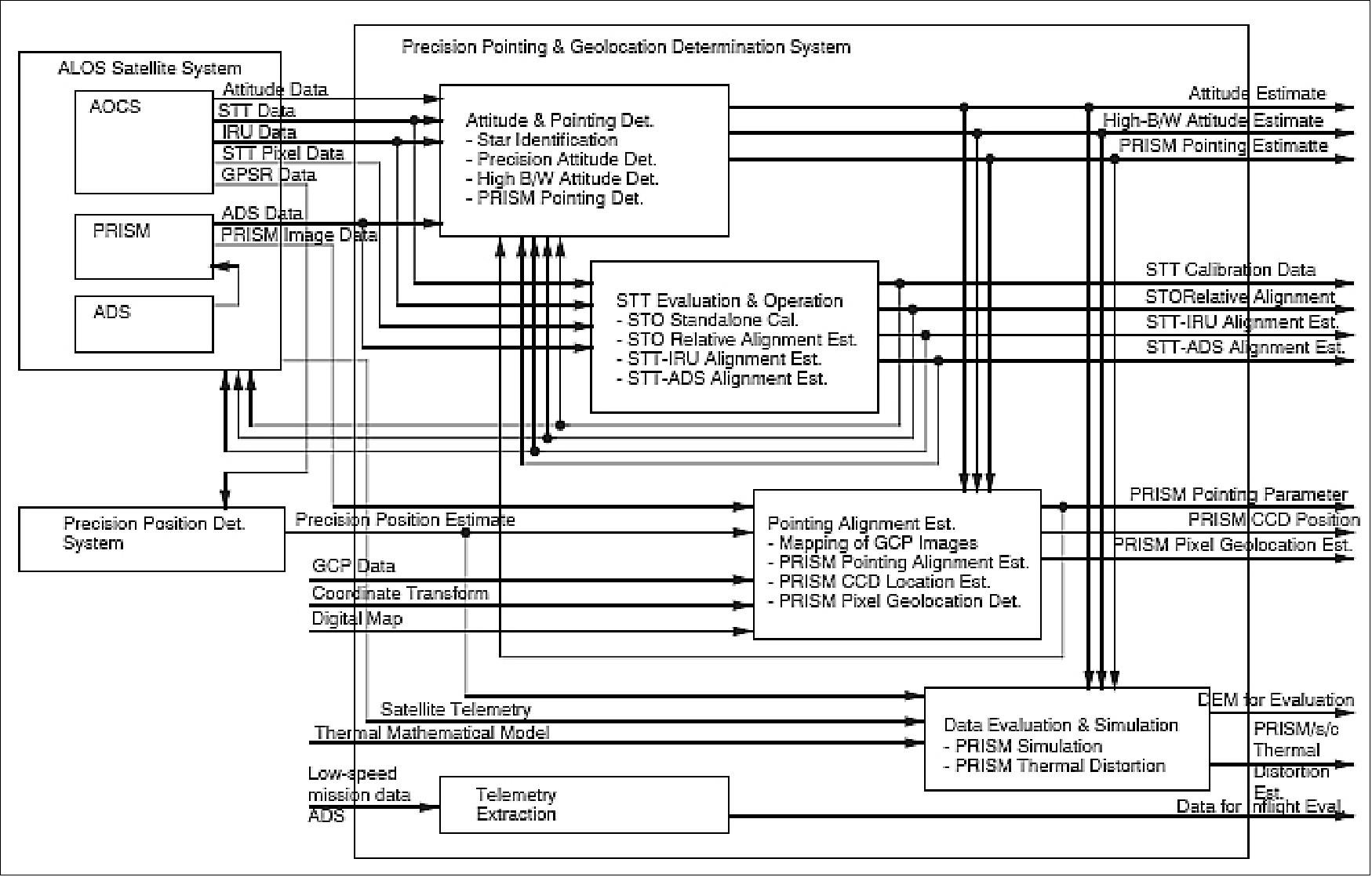
On the ground, JAXA developed for ALOS the PPDS (Precision Pointing and Geolocation Determination System) that provides the pointing determination with an accuracy of 2.0º x 10-4, the attitude determination with the accuracy of 1.4º x 10-4, and the geolocation determination with an accuracy of 3 ~ 7.5 m. The system was developed for the geometric correction of PRISM imagery and the in-flight evaluation of the ALOS pointing requirements.
Launch
The ALOS spacecraft was launched on January 24, 2006 by a Japanese H-IIA rocket from the Tanegashima Space Center, Japan.
Orbit: Sun-synchronous near-recursive circular orbit, altitude = 691.65 km, inclination = 98.16º, repeat cycle = 46 days (with a sub-cycle of 2 days for event monitoring), local time at descending node 10:30 AM (±15 min), period = 98.51 min, orbits/day = 14 27/46.
RF Communication and Data Distribution
The primary data transmission link is via DRTS (Data Relay and Test Satellite of Japan) in Ka-band for mission data at 240 Mbit/s, and S-band for TT&C data. In addition there is an X-band downlink for maximum data rates of 120 Mbit/s. This is considered a backup only for AVNIR-2 data. A further Ka-band downlink at 120 Mbit/s is considered via the Artemis relay satellite of ESA. - ALOS is equipped with a solid-state recorder with a capacity of 768 Gbit using 64 Mbit DRAM technology. The storage capacity is sufficient for a 50 minute recording of a 240 Mbit/s data stream. The data rate capabilities of the recorder are: 360 Mbit/s for recording and 240 Mbit/s for readout of playback data.
The observation data produced by ALOS amount to about 1 TByte/day. In view of this large amount of data, JAXA proposed the concept of ADN (ALOS Data Node) to the international EO community. The benefits of this concept are:
• To increase capacity for ALOS data processing and archiving
• To accelerate practical and scientific use of ALOS data
• To increase international cooperation including joint validation and joint science study activities
• To enhance service for potential users.
The ALOS global acquisition concept consists of the following nodes:
Agency | General zone of coverage |
JAXA, RESTEC (Remote Sensing Technology Center) is primary distributor | Asia |
ESA with ADEN (ALOS Data European Node) terminal | Europe and Africa |
NOAA/ASF (Alaska Satellite Facility) | North and South America |
Geoscience Australia (GA) | Australia, Oceania |
GISTA (Geo-Informatics and Space Technology Development Agency) | Thailand |
Mission Status
• October 23, 2020: The Advanced Land Observing Satellite (ALOS) from Japan, alongside Europe's Sentinel-1A satellite, provided high-resolution radar data used by researchers to study vertical land motion along California's coast. This study revealed significant subsidence affecting up to 8 million Californians, especially in areas like San Francisco, Los Angeles, and San Diego. Vertical land motion, influenced by both natural processes (like tectonics and sediment compaction) and human activities (such as groundwater extraction and replenishment), can greatly affect local sea level changes, as shown in Figure 7. The detailed radar data from ALOS, with its high spatial resolution, enabled a more precise understanding of these dynamics, aiding long-term resilience planning against sea level rise. 13)
![Figure 7: The map highlights the variability in the rising and falling of land across California’s 1000-mile (1,500 km) coast. Areas shown in blue are subsiding, with darker blue areas sinking faster than lighter blue ones. The areas shown in dark red are rising the fastest. The map was created by comparing thousands of scenes of synthetic aperture radar (SAR) data collected between 2007 and 2011 (ALOS) with more collected between 2014 and 2018 (Sentinel-1A). Blackwell and colleagues looked for differences in the data—a processing technique known as interferometric synthetic aperture radar (InSAR). [image credit: NASA Earth Observatory images by Lauren Dauphin, using data from Blackwell, Em, et al. (2020) and topographic data from the Shuttle Radar Topography Mission (SRTM). Story by Adam Voiland]](/api/cms/documents/163813/5972685/ALOS_Auto1E.jpeg)
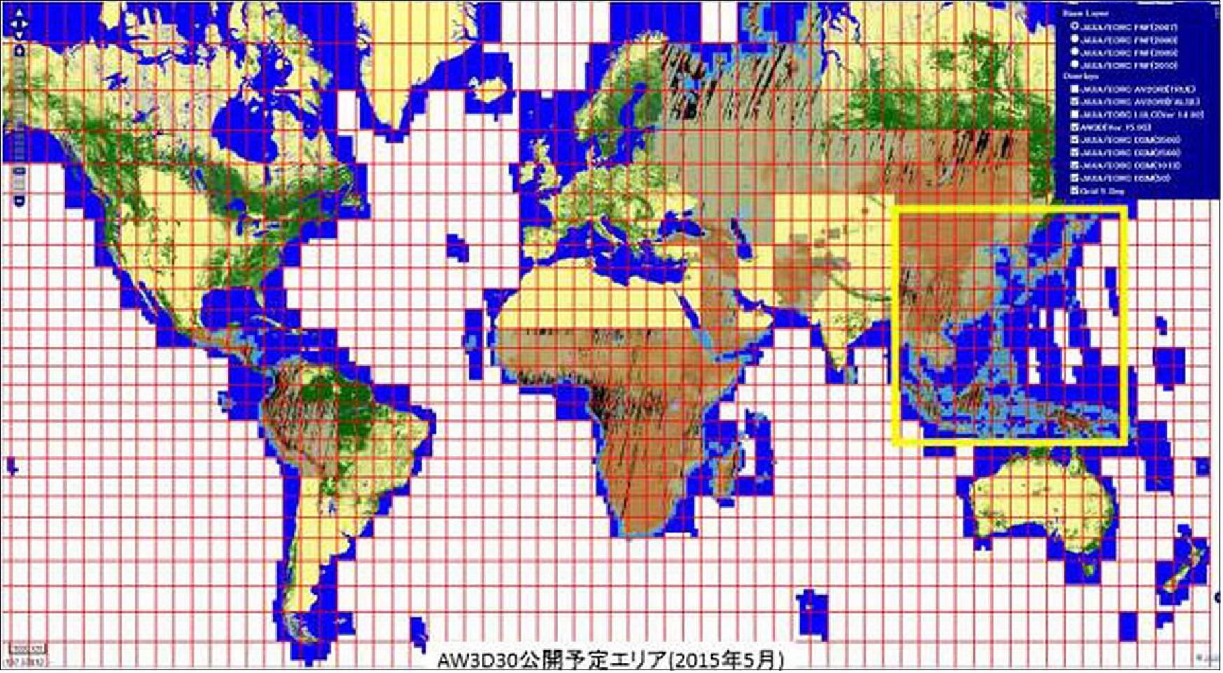
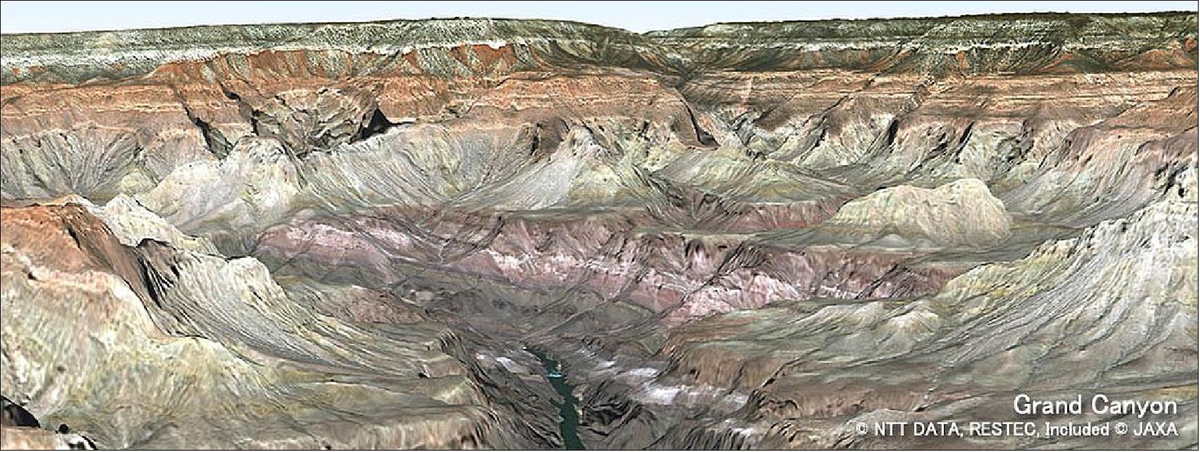
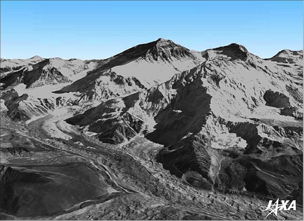
• May 18, 2015: JAXA has released a free, high-resolution elevation dataset, derived from ALOS/Daichi satellite images, which provides 30-meter horizontal resolution digital 3D topographic data (Figure 9). Initially covering East and Southeast Asia, the dataset will eventually span globally between ±82º latitudes. This dataset, based on ALOS's PRISM stereo imager data (Figure 8), offers unparalleled detail with a 5-meter horizontal and vertical resolution. JAXA has enhanced its processing capabilities to generate up to 150,000 maps monthly, aiming for complete global coverage by March 2016. Despite ALOS-1's power failure in 2011, its five years of data have significantly contributed to this comprehensive elevation model project, now managed in collaboration with NTT DATA Corporation.15) 17) 18) 19) 20) 21)
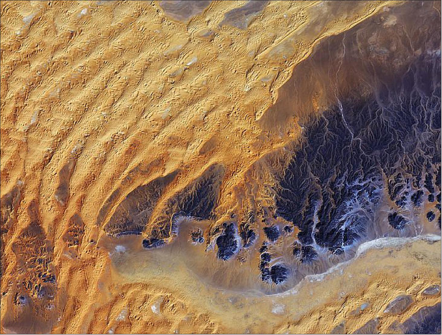
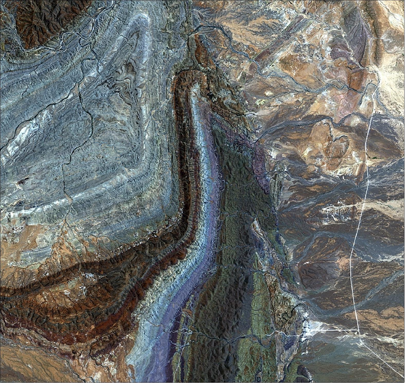
• November 14, 2014: The satellite image of JAXA' s ALOS mission displayed in Figure 10 was captured over southeastern Algeria. ALOS was supported as a Third Party Mission, which means that ESA used its multimission ground systems to acquire, process, distribute and archive data from the satellite to its user community. 24)
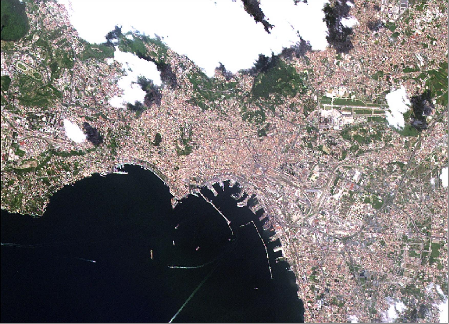
• September 19, 2014: ESA's Earth from Space video program, released the ALOS image of Figure 11 showing Helsinki on the shores of the Gulf of Finland. 26)

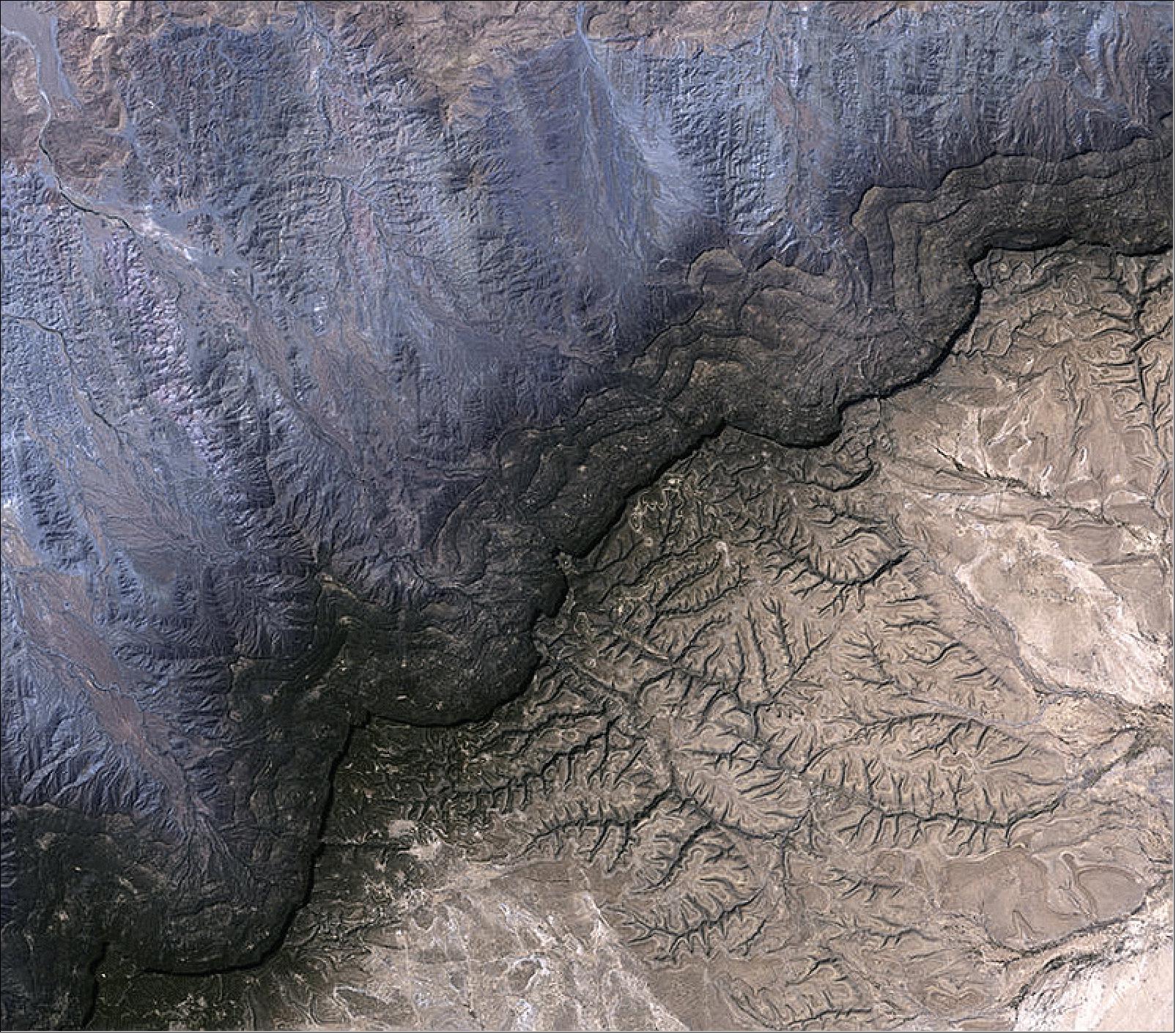
• July 25, 2014: Northern Somalia’s Cal Madow mountain range is pictured in Figure 12 of Japan’s ALOS satellite, released in ESA's Earth from Space video program. ALOS was a TPM (Third Party Mission) of ESA. 27)
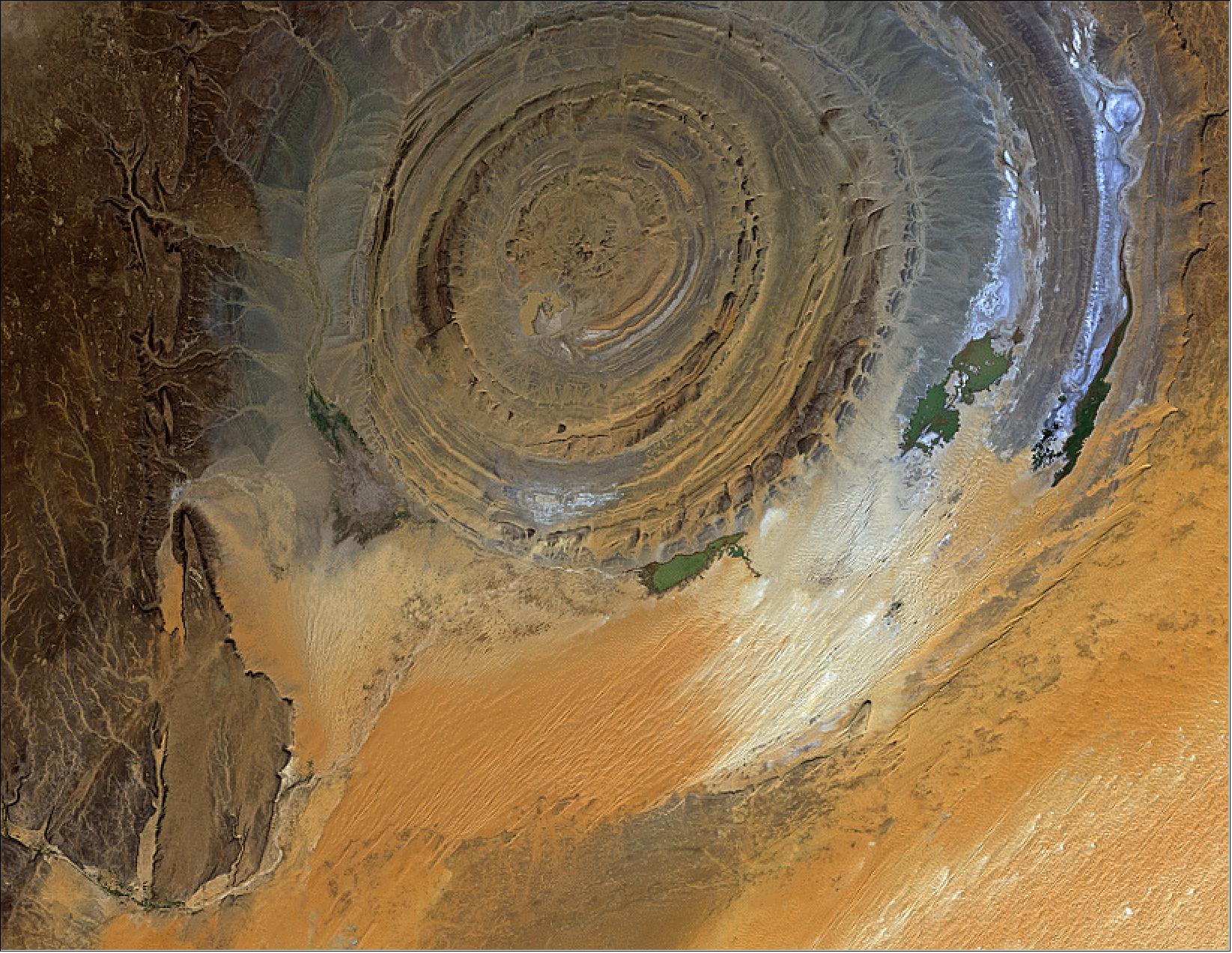
• May 2, 2014: ESA's 'Earth from Space video program' released the image of Figure 13 showing a prominent circular geological feature in the Sahara Desert of west-central Mauritania. 29) 30) 31)
• February 24, 2014: JAXA is creating a highly precise global digital 3D map using 3 million images from the ALOS "DAICHI" satellite, featuring a spatial resolution and height accuracy of 5 meters. This map will aid in mapping, natural disaster damage prediction, and water resource research. Initially producing 100 maps per month for validation, JAXA's advancements now allow for 150,000 maps per month, aiming to complete the global map by March 2016. NTT DATA Corporation will manage the compilation and service provision. Additionally, JAXA will release a global Digital Elevation Model (DEM) with a 30-meter resolution for free to promote widespread use, with Japan's data serving as the base map for this global project. 33) 34) 35)
• December 2013: ALOS image of Flinders Ranges (Figure 15), South Australia, about 500 km north of Adelaide, released in ESA's Earth from Space video program on December 13, 2013. The area pictured is between Flinders Ranges National Park to the south, Vulkathunha-Gammon Ranges National Park to the north and Lake Frome due east (none of which is pictured). 37)
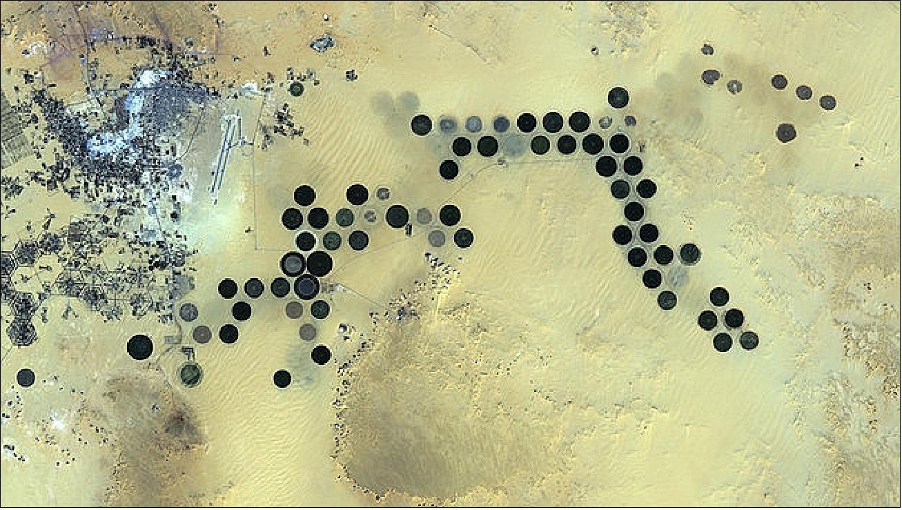
• September 2013: The Al Jawf oasis in southeastern Libya is pictured in this image from Japan’s ALOS satellite. 38)
• May 12, 2011: The ALOS (Daichi) spacecraft, launched on January 24, 2006, was retired after over five years of operation due to an irrecoverable power generation anomaly. Despite its design life of three years, ALOS exceeded expectations, significantly contributing to Earth observations and emergency disaster monitoring, including the Great East Japan Earthquake in March 2011. During its mission, ALOS provided invaluable data, aiding international disaster response and resulting in Japan receiving approximately 5,000 scenes of imagery from global partners. JAXA continues to investigate the causes of the satellite's power issues based on the data obtained before communication was lost. 40)
• April 22, 2011: The ALOS team observed that the satellite had shifted to low load mode, a power-saving mode intended to maintain minimal functionality, resulting in the shutdown of all onboard observation devices due to reduced power generation. JAXA is currently investigating the cause of this issue while implementing necessary measures to address it. 41)
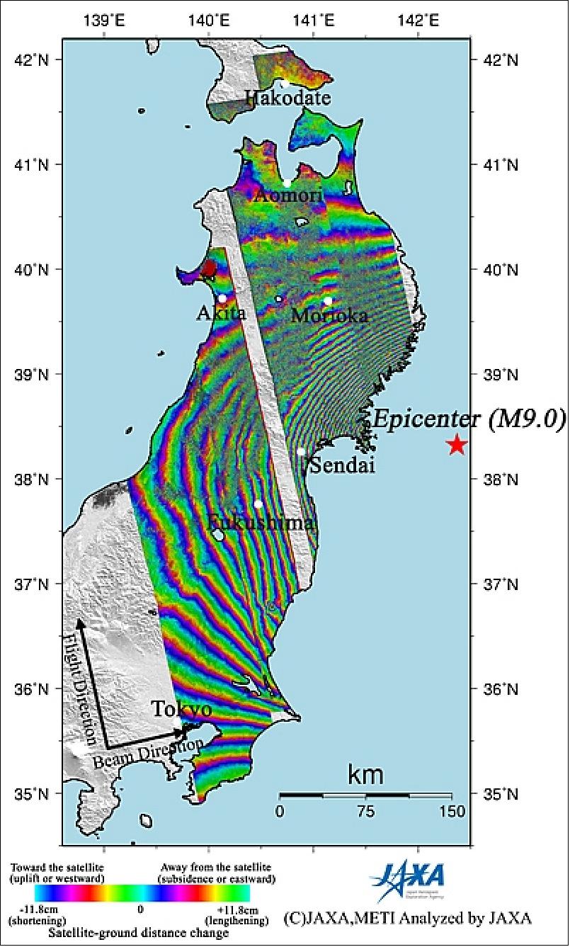
• March 11, 2011: A magnitude 9.0 earthquake struck off the Pacific coast of the Tohoku-Kanto district in Japan, causing a devastating tsunami that led to severe damage in many cities and the loss of over 20,000 lives. In response, JAXA conducted emergency observations using the PALSAR assembly on the ALOS satellite. These observations included differential interferometric SAR (DInSAR) processing to detect crustal deformation caused by the earthquake. 43)
• August 27, 2010: As of spring 2010, the ALOS (Daichi) spacecraft and its payload, including the PALSAR instrument, were operating well after over five years in orbit, exceeding its design life of three years and achieving its goal of five years. ALOS was expected to potentially provide services for more than seven years due to its good condition and the stability and high accuracy of the PALSAR instrument. 44)
• December 20, 2010: a magnitude 6.5 earthquake occurred in southeastern Iran (28.49º N, 59.12º E, 11.8 km in depth). JAXA performed an emergency observation on December 31 using the Phased Array type L-band Synthetic Aperture Radar (PALSAR) instrument of the ALOS satellite. A Differential interferometric SAR (DinSAR) processing was conducted to detect crustal deformation associated with the earthquake. 45)
• August 2008: ALOS has been operated successfully on orbit, delivering a variety of high-resolution images in numerous quantities and contributing to disaster management support many times. The total images observed to date have accumulated 48,500,000 scenes. 235 post-disaster observations have been provided (Ref. 7).
• May 30, 2008: JAXA carried out a communication experiment with the University of Alaska in sending observation data of ALOS (Daichi) to the NASA White Sands Test Facility via the TDRS (Tracking and Data Relay Satellite) system of NASA (TDRS-F10). This represents the world's first data transmission test of this kind.
• July 2007: Various precision orbit control mechanisms have been implemented to meet the stringent requirements for SAR interferometry. The flight results demonstrated that the requirements were achieved, and equator crossing points had been regulated within ±0.5 km from reference ground paths and altitude variations over some geo-locations had been kept within ±0.5 km. 50) 51) 52)
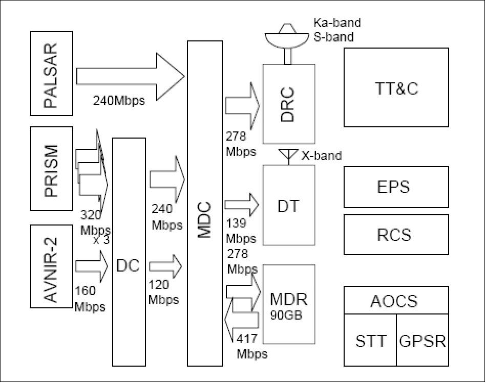
• April 9, 2007: The DRC Data Relay Communication (DRC) antenna suffered a loss of its primary Traveling Wave Tube Assembly (TWTA) for Ka-band transmission (intersatellite link to DRTS), but a redundant TWTA onboard ALOS made up the loss. The Mission Data Handling System (MDHS) has supported its data handling functions (compression, encoding, recording, and transmission) at data rates of 1360 Mbit/s (PRISM: 960 Mbit/s + AVNIR-2: 160 Mbit/s + PALSAR: 240 Mbit/s) properly everyday. The system achieved the world's first 240 Mbit/s Ka-band inter-satellite data transmission and has continued to process the world's largest generated data rate of space-based observation. The Ka-band transmission via DRTS provides an excellent stable link to receive very high bit rate data (277.56 Msample/s) from ALOS.
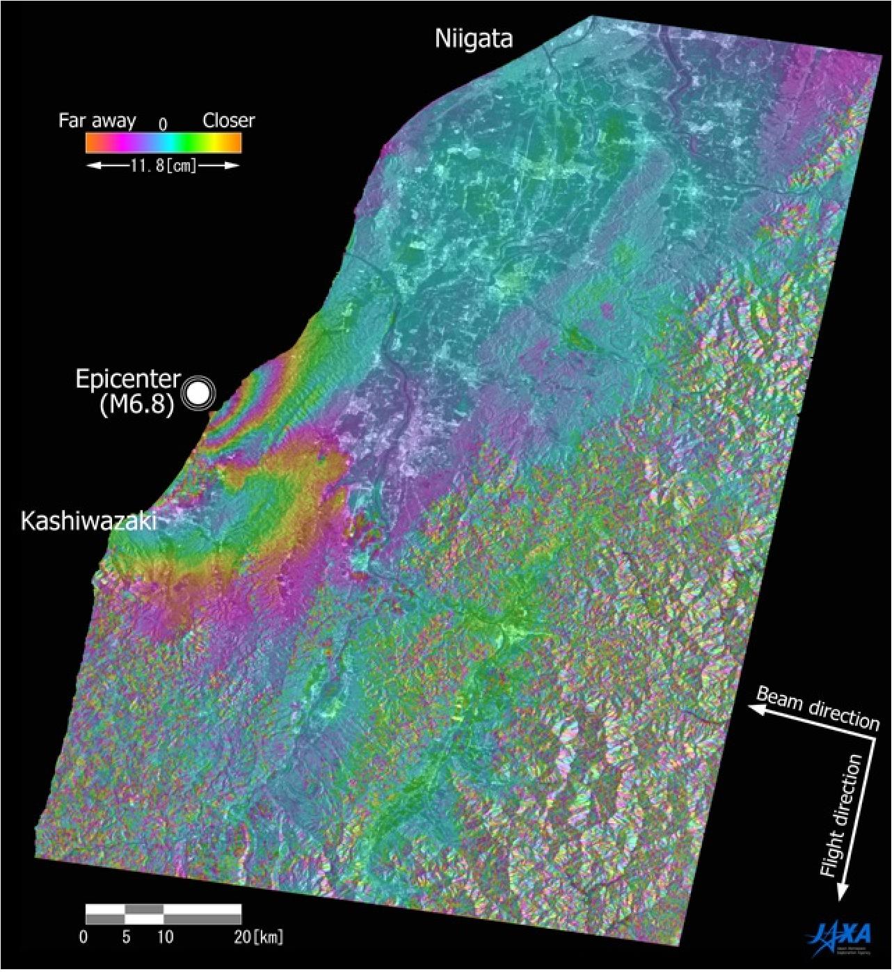
• July 20, 2007: A huge earthquake occurred off Jyo-chuetsu, Niigata Prefecture (60 km south-west of the city of Niigata), at about a depth of 17 km at 10:13 hours on July 16, 2007, Japan Standard Time (JST). JAXA analyzed observation images of PALSAR acquired by ALOS on July 19, 2007 - confirming the pattern of diastrophism. 53)
• March 19, 2007: ALOS had provided support for 66 disaster monitoring requests within the last 14 months - providing imagery to various international, overseas, and domestic organizations such as the International Disaster Charter (IDC) and Sentinel-Asia, a disaster management support system in the Asia-Pacific Region.
• March 2007: Another LLM retreat occurred initiated by power monitoring due to an operational error, although the satellite power system was in a perfect health. In addition, the criteria for RSP control (sub-satellite point cross-track control) were changed to improve SAR interferometry. The calibration parameters for STT and the precision attitude determination system were updated; furthermore the paddle drive control law software was reprogrammed in AOCS to improve attitude stability.
• December 2006: A large solar flare and geomagnetic storm occurred. This required the execution of two sky maneuvers for seven days in total. ALOS retreated automatically into the safe mode (LLM) initiated by attitude check due to a software bug in a ground system and two operational problems.
• July 27, 2007: The commissioning phase of ALOS was successfully completed in April/May 2006 when JAXA initiated a worldwide CAL/VAL campaign together with several international partners to assess the data quality from the three onboard sensors. 54) 55) 56) 57)
• June 27, 2006: The first months after the launch of ALOS was dedicated to the initial check-out of the spacecraft, confirming the capabilities of all bus and mission subsystems and the end-to-end capabilities of the integrated system. On February 14-17, 2006, the first images were captured by PRISM, AVNIR-2, and PALSAR. On February 20, 2006, the first post-disaster emergency monitoring was performed for the Leyte Island landslide in the Philippines. ALOS began its operational phase on October 24, 2006, and started distributing routinely its observational data products in November 2006. 58)
Sensor Complement
PRISM (Panchromatic Remote-sensing Instrument for Stereo Mapping)
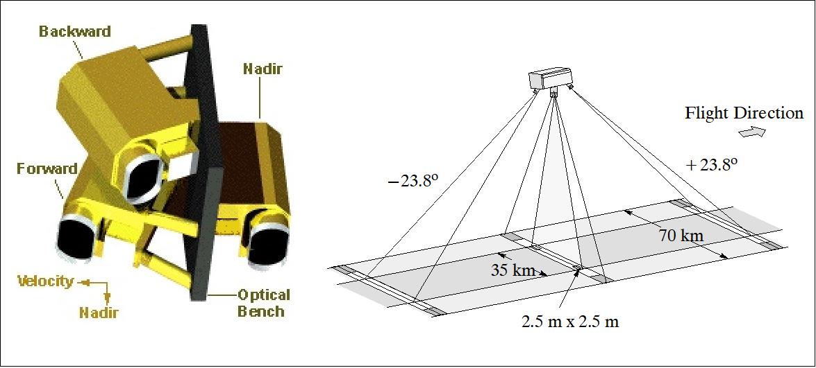
The objective is to obtain high-resolution stereo data (pixel size of 2.5 m) for cartographic applications (extraction of highly accurate digital elevation models, etc.). The instrument is a “three-line imager” with three independent catoptric systems for nadir, forward and backward-looking to achieve along-track stereoscopy. Each of the three telescopes employs a three mirror type optics design (30 cm aperture diameter and 2 m focal length) and several CCD detectors for pushbroom scanning. Six or eight silicon CCDs (5000 pixels each) are physically aligned at each telescope's focal plane. Of the 40,000 pixels per telescope, 14,000 pixels are electronically selected and transferred to the ground station. Thus, a triplet image consists of three (fore, nadir aft-looking) 14,000 pixels/line. - The nadir-looking telescope provides a swath of 70 km width (28,000 readout pixels), each of the fore and aft-looking telescopes provides a swath of 35 km (14,000 pixels per band). The fore and aft telescopes are inclined by ±23.8º from nadir to realize a base to height/ratio of one at an orbital altitude of 692 km. 59)
The PRISM optics are mounted on a rigid optical bench which is thermally controlled within ±3º C to minimize distortions in the optics system.
Parameter | Panchromatic Sensor |
Spectral band (panchromatic) | 0.52-0.77 µm |
Number of optics | 3 (nadir, forward, and backward pointing) |
Fore and aft imager inclination | ± 23.8º |
SNR, MTF | > 70, > 0.2 |
IFOV (spatial resolution or GSD) | 2.5 m (3.61 µrad) |
Swath width | 35 km (triplet stereo observations) |
FOV | ≥ 7.6º (swath) |
Stereo imaging | B/H = 1.0 |
Nr of detector readout pixels | 28,000 (70 km swath), 14,000 (35 km swath) |
Gimbal angle | ±1.5º (cross-track, triplet mode) |
Data quantization | 8 bit/pixel |
Data rate | 960 Mbit/s of raw data, a lossy JPEG compression is used based on DCT quantization and Huffman |
Calibration: PRISM has electrical calibration sources onboard. They are used to estimate gain and offset of the amplifiers. For absolute and relative radiometric calibration, PRISM uses AVNIR-2 data. AVNIR-2 is calibrated using internal calibration lamps. During the commissioning phase, an extensive calibration and product validation campaign is being conducted. Highly accurate ground control points (GCP) are necessary to calibrate the geometric accuracy and to validate the generated DEMs (Digital Elevation Models). 60) 61)
Note: PRISM is now a separate sensor with stereo capability what used to be initially the “panchromatic sensor portion” of AVNIR-2.
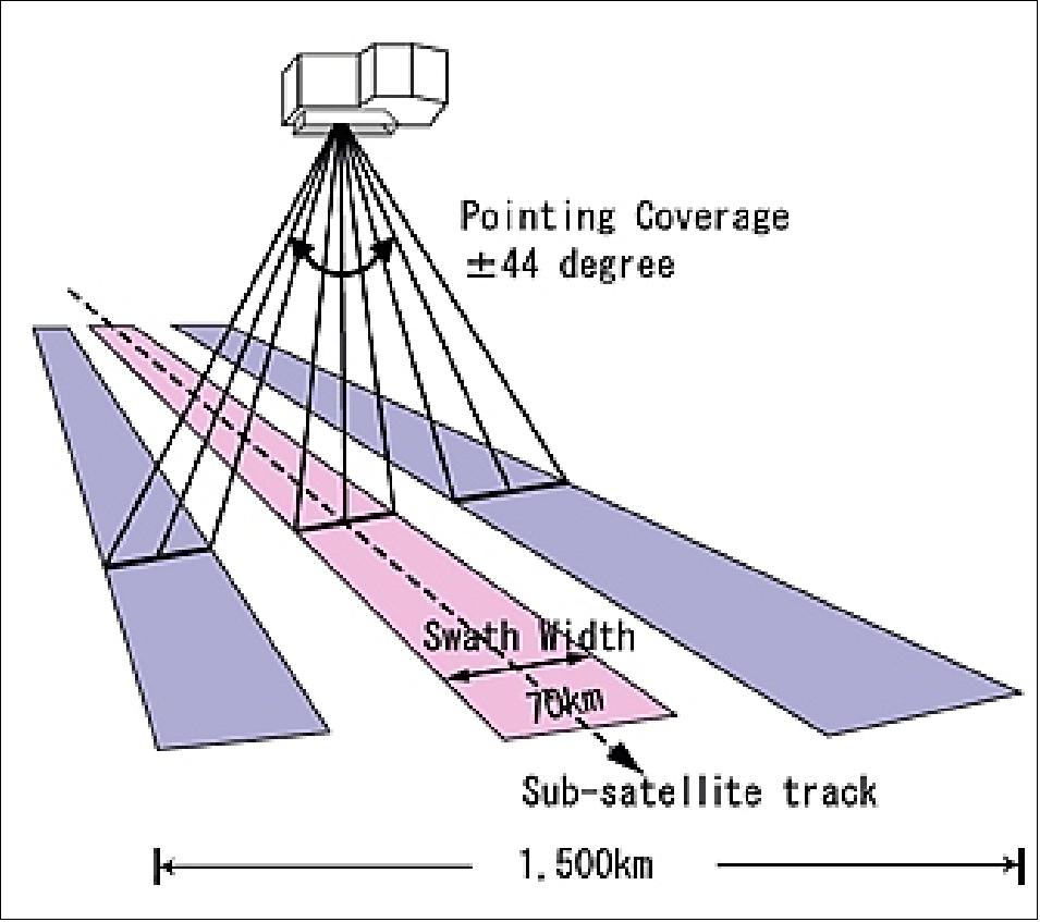
AVNIR-2 (Advanced Visible and Near-Infrared Radiometer - 2)
AVNIR-2 is a JAXA instrument of AVNIR heritage flown on ADEOS, built by Mitsubishi Electric Corporation. Objective: provision of high-resolution (10 m) multispectral data. The instrument optics are of “folding Schmidt” type. The telescope aperture is 24 cm in diameter, it has a focal length of about 800 mm. AVNIR-2 features a pointing capability of ±44º in the across-track direction, thereby providing a wide field of regard (FOR) for disaster monitoring. The silicon CCD detector arrays have 7000 pixels per line (pushbroom type instrument). Applications: monitoring of regional environment (land coverage and land-use maps, etc.). A quasi-lossless data compression technique of DPCM (Differential Pulse Code Modulation) with Huffman coding is employed for a source data reduction from 160 Mbit/s to 120 Mbit/s. 62)
Calibration: AVNIR-2 uses two onboard calibration lamps which are used for absolute and relative calibration sequences. In addition, internal electrical calibration is provided.
Parameter | Multispectral Sensor |
Spectral bands (4) |
|
Detectors | Silicon CCD, 7000 pixels/band |
SNR, MTF | >200, > 0.25 (at Nyquist frequency) |
IFOV (spatial resolution) | 10 m (at nadir, 14.28 µrad) |
Swath width, (FOV) | 70 km, 5.8º |
Gimbal angle (FOR) | ±44º in cross-track instrument pointing capability |
MTF (Modulation Transfer Function) | Band 1-3 ≥ 0.25; band 4 ≥ 0.20 |
Data quantization | 8 bit |
Data rate | about 160 Mbit/s of raw data, a quasi-lossless (DPCM) data compression technique reduces |
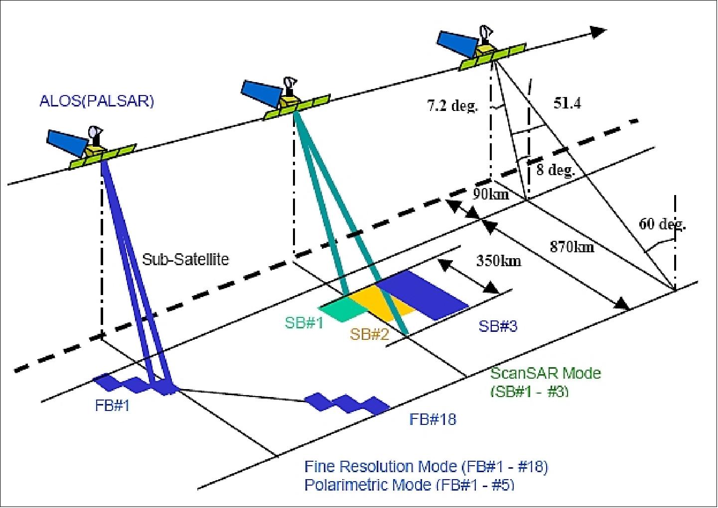
PALSAR (Phased Array L-band Synthetic Aperture Radar)
PALSAR was jointly developed by JAXA, JAROS (Japan Resources Observation System Organization) and METI (Ministry of Economy, Trade & Industry), heritage of SAR on JERS-1. PALSAR is a side-looking phased array L-band instrument with a pointing capability from 8 to 60º of incidence angle. The SAR antenna is of size: 8.9 m (length) and 3.1 m in width. An array of 80 transmitting/receiving modules (T/R) is mounted behind the antenna panels. Electrical beamsteering in elevation is provided. 63)
PALSAR features four operational modes:
• FB (Fine resolution Beam) mode: FB comprises 18 selections in the off-nadir angle range between 9.9º and 50.8º, each with 4 alternative polarizations: single polarization HH or VV, and dual polarization HH+HV or VV+VH. The bandwidth is 28 MHz in single polarization and 14 MHz in the dual-polarization modes. Out of the 72 possible FB modes, two have been selected for operational use.
• The 14 MHz polarimetric mode provides the full quad-polarization (HH+HV+VH+VV) scattering matrix with 12 alternative off-nadir angles between 9.7º and 26.2º.
• ScanSAR is available at a single polarization only (HH or VV) and can be operated with 3, 4, or 5 sub-beams transmitted in short (14 MHz) or long bursts (28 MHz). Out of the 12 ScanSAR modes available, the sort-burst, HH polarization, 5-beam mode has been selected for operational support. It features a 350 km swath width with an incidence angle range of 18-43º.
• The direct transmission (or downlink) mode is a contingency backup mode which allows the downlink of the (degraded, 14 MHz) FB mode data to local ground stations in case the high-speed DRTS (Data Relay and Test Satellite) becomes unavailable.
Polarization is changed in every pulse of transmission signal, and dual polarization signals are simultaneously received. The operation is limited in lower incident angle in order to achieve higher performances. At the nominal off-nadir angle (21.5º), the swath width is 30 km with 30 m spatial resolution under the maximum data rate condition (240 Mbit/s). 64)
Polarization | Off-nadir angle (swath, resolution) | Ascending/descending | Comment |
HH | 41.5 (70 km, 10 m) | Ascending | Operational |
HH+HV | 41.5 (70 km, 20 m) | Ascending | Operational |
HH+HV+VH+VV | 21.5 (30 km, ~ 30 m) | Ascending | Operational |
ScanSAR (HH) | 5-beam mode (350 km, ~100 m) | Descending | Operational |
HH |
| Descending | Limited acquisitions only |
HH |
| Descending | Limited acquisitions only |
Parameter | Fine Beam (high-resolution) Mode | Direct downlink Mode | ScanSAR Mode | Polarimetry Mode (with duty cycle) | |
| FBS | FBD (Dual‐Pol) |
|
|
|
Center frequency | 1270 MHz (L-band) | ||||
Chirp bandwidth | 28 MHz | 14 MHz | 14 MHz | 14 MHz, 28 MHz | 14 MHz |
Polarization | HH, VV | HH+HV | HH/HV or | HH or VV | HH/HV+VV/VH |
Incidence angle | 9.9-50.8º | 9.7-26.2º | 8º-60º | 18º-43º | 8º-30º |
Spatial resolution (range) | 7-44 m | 14-88 m | 14-88 m | 100 m multi-look | 30 m |
Swath width | 40 - 70 km | 250-350 km | 30 km | ||
Data quantization | 5 bit | 5 bit | 3 or 5 bit | 5 bit | 3 or 5 bit |
Source data rate | 240 Mbit/s | 120 Mbit/s | 120 or 240 Mbit/s | 240 Mbit/s | |
Radiometric accuracy | Scene: 1 dB, Orbit:1.5 dB | ||||
Parameter | Value | Parameter | Value |
Bandwidth | 28.0/ 14.0 MHz | Pulse width | 27.0/16.0 µs (full pol mode) |
Sampling frequency | 32/16 MHz | PRF | 1500 ~2500 Hz |
Observation side | right-hand side | PRF changes/orbit | 7 times in a half orbit |
No of antenna beams | 18+5 (ScanSAR) | Peak power | 2 kW (transmit) |
Chirp | Down chirp (digital) | No of T/R modules | 80 |
Antenna size | 8.9 m (azimuth) x 3.1 m (elev.) | Antenna mass | 500 kg |
Instrument mass | 600 kg (total PALSAR) | No of ops modes | 132 |
The high PALSAR data rates of 240 Mbit/s, generated in Fine, ScanSAR, and Polarimetric modes, will be transmitted mainly via DRTS (Data Relay Test Satellite) of JAXA. The modes of Direct downlink and ScanSAR (120 Mbit/s) can be received directly by the JAXA ground segment. The observation time of PALSAR will be in the order of 70 min/orbit (or about 70% duty cycle). 65) 66)
The NE (Noise Equivalent) σo (sigma zero) in Direct downlink mode is 3dB, better than that in Fine mode because the bandwidth of the receiver is half. Signal to ambiguity ratio (S/A) is specified both in azimuth and in range individually as more than 16dB within 70 km swath / 21dB within 60km swath at an off-nadir angle of 34.3º in Fine mode, and more than 21dB at #4 scan (off-nadir angle 34.1º) in ScanSAR mode.
The ALOS instruments are capable to observe the surface of the entire world within the following limits:
• Any place within two days
• Around the equator: about 60% of the area within one day
• At latitudes of 35º: about 70% of the area within one day
• At latitudes larger than 55º: any place every day (provided there is no cloud cover for the optical instruments).
Daytime observation modes: PRISM (fore, nadir & aft) and AVNIR-2 simultaneously
Nighttime observation modes: PALSAR (Note: AVNIR-2 and PALSAR are able to operate simultaneously).
PALSAR calibration is provided with PARC (Polarimetric Active Radar Calibrator) as well as by other means. 67) 68) 69) 70)
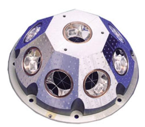
RRA (RetroReflector Array)
The objective is to provide support for precise orbit determination. The corner cubes are made of the highest quality fused silica. Their performance is optimized at the green wavelength (532 nm). The corner cubes are symmetrically mounted on a hemispherical surface with one nadir-looking corner cube in the center, surrounded by an angled ring of eight corner cubes. This will allow laser ranging in the field of view angles of 360º in azimuth and 60º elevation around the perpendicular to the satellite's -Zs Earth panel.
Ground Segment
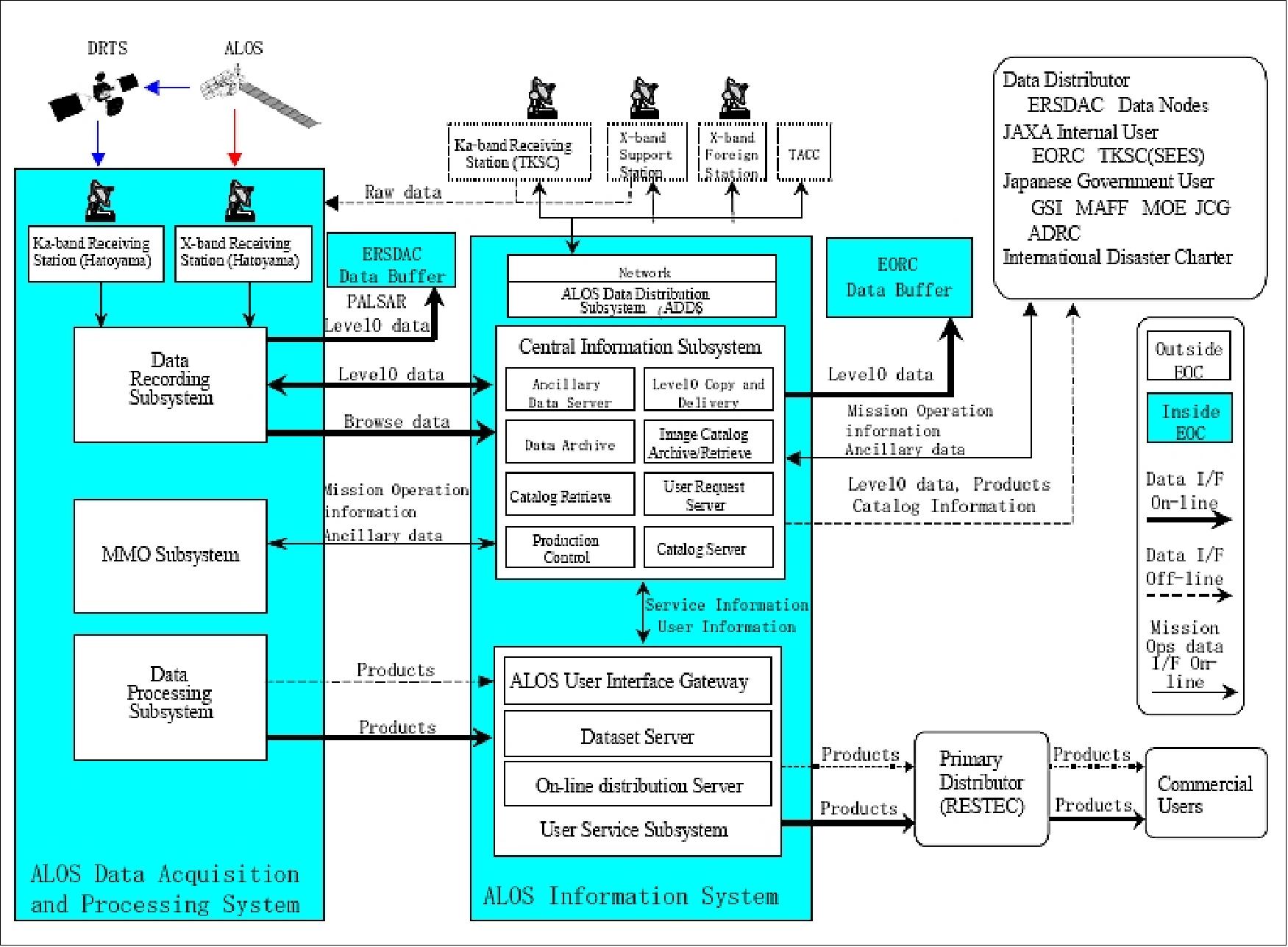
The ALOS ground data system function is allocated at JAXA/EOC (Earth Observation Center) for the provision of mission operation planning, data reception and recording, processing, archiving, and the distribution of ALOS data products. 71) 72) 73)
ALOS Data Distribution Policy
The significance of ALOS is its ability to provide global coverage of land observation and to transmit this huge amount of data acquired. JAXA seeks to implement the ADN (ALOS Data Node) concept for processing and utilizing ALOS data through international cooperation. The ALOS Data Node consists of one representative organization in each region and cooperative organizations including the data distributors. All the ALOS data is downlinked to JAXA's Earth Observation Center (EOC) via a data relay satellite or directly. JAXA will transfer the regional level-0 data it has obtained to the ALOS Data Node. The ALOS Data Node is responsible for providing regional level-1 data upon request from data users, including JAXA, throughout the ALOS mission life.
The current plan is to divide the entire world into four regions: Asia, Europe and Africa, North and South America, and Australia and Oceania. The Data Nodes will serve both as a regional ALOS data center and a scientific research center. Example Data Nodes are: 74) 75) 76)
• JAXA appointed RESTEC (Remote Sensing Technology Center) of Tokyo as the Primary Distributor (PD). RESTEC serves as the regional distributor in the Asia and Russian area as well as the coordinating agency among all of the regional distributors. The PALSAR products are produced at ERSDAC (Earth Remote Sensing Data Analysis Center), Japan.
• AADN (Americas ALOS Data Node) is provided by NOAA and ASF (Alaska Satellite Facility) at the Geophysical Institute, University of Alaska, Fairbanks. ASF and its partners will provide Level 0, Level 1 and higher order products to commercial and research users throughout North, Central and South America.
• ADEN (ALOS Data European Node) is provided by ESA (located at Esrange, Kiruna, Sweden). ESA is supporting ALOS as a 'Third Party Mission', which means the Agency utilizes its multi-mission ground systems of existing national and industrial facilities and expertise to acquire, process and distribute data from the satellite. 77) 78)
• NASA's TDRSS (Tracking and Data Relay Satellite System) started the downloading of ALOS (Daichi) SAR imagery in April 2010 - based on a collaboration agreement between JAXA and NASA in June 2009 (and one signed on April 13, 2010). The aim is to dramatically increase the frequency of observations for earthquake hazards, the decline of forests and changing water resources in North and South America.
The mutual agreement is part of the JAXA-NASA partnership in the field of satellites. The collaborative relationship includes JAXA's onboard devices on NASA's Aqua satellite and TRMM (Tropical Rainfall Measuring Mission), both of which are currently in operation, and NASA's onboard equipment on JAXA's Advanced Earth Observing satellites (ADEOS and ADEOS-II) in the past. In addition, NASA and JAXA plan to launch NASA's GPM (Global Precipitation Mission) on a JAXA launcher in 2013. 79) 80)
NASA's EDOS (Earth Observing System Data Operations System) multimission high-rate system provided operational support of ALOS data starting in April, 2010, and provided continuous operations until April, 2011 when the ALOS mission ended. EDOS successfully captured approximately 1,460 ALOS passes and processed approximately 36.5 TB of data during the one-year operational period. 81)
The main concept of the ALOS data policy should be that each Data Node would be allowed to handle their regional data according to its own data policy. International talks on this concept are about to produce an agreed inter-Node distribution policy defining an interface where the respective regional policies will meet. The whole mechanism will be a combination of de-centralized research and non-research data distribution. A private consortium may be established for promoting commercial data use.
At a multilateral level, nations have not been able to reach a coherent, effectively functioning data policy despite decades of lengthy discussions. If this Data Node concept is successfully implemented, it may demonstrate an effective model of a program-oriented approach to an integrated, disseminated data policy.
The ALOS Kyoto & Carbon Initiative is an international endeavour initialized by JAXA (former NASDA), with the main objective to support information needs raised by the UNFCCC (United Nations Framework Convention on Climate Change) Kyoto Protocol and by the international global carbon cycle science community, by provision of systematic, consistent, repetitive and regional scale data of the global forest cover. Of central importance for the Initiative is a Dedicated Data Acquisition Strategy for the polarimetric PALSAR instrument sensor onboard ALOS. 82)
PALSAR data distribution: Since JAXA and METI/JAROS (Ministry of Economy, Trade and Industry/Japan Resources Observation System Organization) jointly developed the PALSAR instrument, METI has an equal right to distribute the PALSAR data. Hence, ERSDAC (Earth Remote Sensing Data Analysis Center) of Tokyo, under METI agreement, will also distribute the PALSAR data. However, the ERSDAC initiative is outside of the ADN concept.
ALOS Kyoto and Carbon Initiative
JAXA has been working on the establishment of the ”ALOS Kyoto and Carbon Initiative” since 2003. The Initiative, led by JAXA/EORC, is being carried out as cooperative research with 20 international research institutions. The agreements were finalized on Aug. 23, 2007. The project started on Sept. 3, 2007. 83) 84)
The purpose of this project is to study the relationship between changes in the global environment and changes in forests, their surrounding areas, swamplands and deserts, which account for about 30% of the global land area, by observing their long-term and seasonal changes in a broad scope through the onboard synthetic aperture radar of the ALOS. (PALSAR). The study is based on the analysis of the observation data as well as a site survey. For this purpose, JAXA will carry out global observations including on tropical rain forests in South America (Amazon) Southeast Asia, and Central Africa, and the boreal forests in Siberia, Canada, and Alaska. Acquired data will be transmitted to each institution via exclusive online networks within three months after it is received at the Earth Observation Center (Hatoyama-machi, Saitama) of JAXA. In the case of data from the Amazon area, it is converted to images immediately, and provided to IBAMA (Brazilian Institute of Environment and Renewable Resources) within 10 days.
References
1)) T. Hamazaki, “Overview of the Advanced Land Observing Satellite (ALOS): Its Mission Requirements, Sensors, and a Satellite System,” presented to ISPRS Joint Workshop “Sensors and Mapping From Space 1999,” International Society for Photogrammetry and Remote Sensing (ISPRS), Hannover, Germany, Sept. 27-30, 1999
2) Y. Osawa, H. Wakabayashi, K. Toda, T. Hamazaki, “Advanced Land Observing Satellite (ALOS): Mission Requirements, Payloads and Satellite System,” paper of NASDA provided by K. Misawa
3) Masanobu Shimada, “Advanced Land Observation Satellite (ALOS) and its follow-on satellite, ALOS-2,” Proceedings of the 4th International POLinSAR 2009 Workshop, Jan. 26-30, 2009, ESA/ESRIN, Frascati, Italy, URL: http://earth.esa.int/workshops/polinsar2009/participants/535/pres_8_Shimada_535.pdf
4) Yuji Osawa, “Characteristics of the ALOS forapplications in disaster management,” Asian WS on Satellite Technology Data Utilization for Disaster Monitoring, Jan. 20, 2005, URL: http://www.aprsaf.org/data/malaysia_tecshop_data/asian_disaster_data/2_osawa.pdf
5) T. Iwata, et. al., “Precision Attitude and Orbit Control System for the Advanced Land Observing Satellite (ALOS),” AIAA Guidance, Navigation, and Control Conference, AIAA-2003-5783, Austin, TX, USA., Aug. 11-14, 2003
6) T. Iwata, M. Uo, T. Kawahara, M. Sugiho, “Ground-Based Precision Attitude Determination for the Advanced Land Observing Satellite (ALOS),” Proceedings of 25th ISTS (International Symposium on Space Technology and Science) and 19th ISSFD (International Symposium on Space Flight Dynamics), Kanazawa, Japan, June 4-11, 2006, paper: 2006-d-32
7) Takanori Iwata, Takeo Tadono, Tetsuo Kawahara, Masakazu Abe, “Precision Pixel Geolocation Determination for the Advanced Land Observing Satellite (ALOS),” Proceedings of the 59th IAC (International Astronautical Congress), Glasgow, Scotland, UK, Sept. 29 to Oct. 3, 2008, IAC-08.C1.7.9
8)) Takanori Iwata, Hoshiko Takayasu, Noboru Muranaka, Ryoichi Kashikawa, Koshi Sato, “On-Orbit Calibration of Precision Star Tracker for the Advanced Land Observing Satellite (ALOS),” Proceedings of the 60th IAC (International Astronautical Congress), Daejeon, Korea, Oct. 12-16, 2009, IAC-09.C1.9.5
9) T. Iwata, “Precision attitude and position determination for the Advanced Land Observing Satellite (ALOS),” Proceedings of SPIE, Vol. 5659 , `Enabling Sensor and Platform Technologies for Spaceborne Remote Sensing,' G. J. Komar, J. Wang, T. Kimura, Editors, Jan. 2005, pp. 34-50, Conference location: Honolulu, HI, USA, Nov. 9, 2004
10) T. Iwata, K. Sato, R. Kashikawa, H. Takayasu, M. Yamamoto, “Precision Star Tracker for the Advanced Land Observing Satellite (ALOS),” Proceedings of the 27th AAS Rocky Mountain Guidance and Control Conference (J. D. Chapel, R. D. Culp, ed), Vol. 118, Feb. 4-8, 2004, Breckenridge, CO, pp. 291-310, AAS-04-027
11) T. Iwata, “Precision Geolocation Determination and Pointing Management for the Advanced Land Observing Satellite (ALOS),” IEEE/IGARSS 2003, Toulouse, France, July 21-25, 2003
12) MEXT/JAXA Agency Report on Earth Observation Activities 20th CEOS Plenary meeting, Buenos Aires, Argentina, November 9, 2006
13) ”California’s Rising and Sinking Coast,” NASA Earth Observatory, Image of the Day for 23 October 2020, URL: https://earthobservatory.nasa.gov/images/147439/californias-rising-and-sinking-coast
14) “New York City,” ESA Earth observation image of the week, July 17, 2015, URL: http://www.esa.int/spaceinimages/Images/2015/07/New_York_City
15) “World Elevation Data (30 meter mesh version) is now available at JAXA's site free of charge!,” JAXA Press Release, May 18, 2015, URL: http://global.jaxa.jp/press/2015/05/20150518_daichi.html
16) http://global.jaxa.jp/press/2015/05/20150518_daichi.html#at1
17) “Precise Global Digital 3D Map "ALOS World 3D",” JAXA/EORC, URL: http://www.eorc.jaxa.jp/ALOS/en/aw3d/index_e.htm
18) “ALOS Global Digital Surface Model "ALOS World 3D - 30m" (AW3D30),” JAXA/EORC, URL: http://www.eorc.jaxa.jp/ALOS/en/aw3d30/index.htm
19) ALOS World 3D Topographic Data,” NTT Data, RESTEC, Brochure, URL: http://alos-world3d.jp
/en/public/AW3Dbrochure_en.pdf
20) Junichi Takaku, Takeo Tadono, Ken Tsutsui, “Generation of high resolution global DSM from ALOS PRISM,” The International Archives of the Photogrammetry, Remote Sensing and Spatial Information Sciences, Volume XL-4, 2014, ISPRS Technical Commission IV Symposium, 14 – 16 May 2014, Suzhou, China, URL: http://www.int-arch-photogramm-remote-sens-spatial-inf-sci.net
/XL-4/243/2014/isprsarchives-XL-4-243-2014.pdf
21) T. Tadono, H. Ishida, F. Oda, S. Naito, K. Minakawa, H. Iwamoto, “Pricise global DEM generation by ALOS PRISM,” ISPRS Annals of the Photogrammetry, Remote Sensing and Spatial Information Sciences, Volume II-4, 2014, ISPRS Technical Commission IV Symposium, 14 – 16 May 2014, Suzhou, China, URL: http://www.isprs-ann-photogramm-remote-sens-spatial-inf-sci.net/II-4/71/2014/isprsannals-II-4-71-2014.pdf
22) World 3D Topographic Data, URL: http://alos-world3d.jp/en/index.html
23) “NTT DATA and RESTEC launch the World’s Most Precise Digital 3D Map of the Entire World,” February 24, 2014, URL: http://www.nttdata.com/global/en/news-center/others/2014/022400.html
24) “Sahara desert, Algeria,” ESA, image released on Nov. 14, 2014 as 'Earth observation image of the week,' URL: http://www.esa.int/spaceinimages/Images/2014/11/Sahara_desert_Algeria
25) “Mumbai, India,” ESA, Oct. 24, 2014, URL: http://www.esa.int/spaceinimages/Images/2014/10/Mumbai_India
26) “Helsinki, Finland,” ESA's Earth from Space video program, Sept. 19, 2014, URL: http://www.esa.int/spaceinimages/Images/2014/09/Helsinki_Finland
27) “Cal Madow mountain range, Somalia,” ESA, July 25, 2014, URL: http://www.esa.int/spaceinimages/Images/2014/07/Cal_Madow_mountain_range_Somalia
28) “Mount Kenya,” ESA, June 6, 2014, URL: http://www.esa.int/spaceinimages/Images/2014/06/Mount_Kenya
29) “Richat structure, Mauritania,” featured in ESA's Earth from Space video program, May 2, 2014, URL: http://www.esa.int/spaceinimages/Images/2014/05/Richat_structure_Mauritania
30) “Richat Structure,” Wikipedia, URL: http://en.wikipedia.org/wiki/Richat_Structure
31) “Richat Structure, Mauritania,” NASA, March 23, 2008, URL: http://www.nasa.gov/multimedia/imagegallery/image_feature_528.html
32) “Margarita Island, Venezuela,” featured in ESA's Earth from Space video program, March 7, 2014, URL: http://www.esa.int/spaceinimages/Images/2014/03/Margarita_Island_Venezuela
33) “DAICHI Data Application for Compilation of Global Digital 3D Map with World's Best Precision,” JAXA Press Release, Feb. 24, 2014, URL: http://www.jaxa.jp/press/2014/02/20140224_daichi_e.html#at
34) “ALOS World 3D Topographic Data,” NTT Data, Feb. 24, 2014, URL: http://alos-world3d.jp/en/index.html
35) “NTT DATA and RESTEC launch the World’s Most Precise Digital 3D Map of the Entire World,” NTT DATA Corporation, Remote Sensing Technology Center of Japan (RESTEC), Feb. 24, 2014, URL: http://www.nttdata.com/global/en/news-center/others/2014/022400.html
36) “Heart of the Atacama,” ESA, released by ESA's Earth from Space video program on Feb. 14, 2014, URL: http://www.esa.int/spaceinimages/Images/2014/02/Heart_of_the_Atacama
37) “Flinders Ranges, South Australia,” ESA, released by ESA's Earth from Space video program on Dec. 13, 2013, URL: http://www.esa.int/spaceinimages/Images/2013/12/Flinders_Ranges_South_Australia
38) “Earth from Space: Sahara Oasis,” ESA, Sept. 20, 2013, URL: http://www.esa.int/Our_Activities/Observing_the_Earth/Earth_from_Space_Sahara_oasis
39) “Earth from Space: Salty Turkey,” ESA, August 30, 2013, URL: http://www.esa.int/Our_Activities/Observing_the_Earth/Earth_from_Space_Salty_Turkey
40) “DAICHI (ALOS) Operation Completion,” JAXA, May 12, 2011, URL: http://www.jaxa.jp/press/2011/05/20110512_daichi_e.html
41) “Advanced Land Observing Satellite 'DAICHI' (ALOS) Power Generation Anomaly,” JAXA Press Release, April 22, 2011, URL: http://www.jaxa.jp/press/2011/04/20110422_daichi_e.html
42) “Earth from space: Great Blue Hole,” ESA, April 26, 2013, URL: http://www.esa.int/Our_Activities/Observing_the_Earth/Earth_from_Space_Great_Blue_Hole
43) “ALOS/PALSAR Observation Results of the Magnitude-9.0 Earthquake off the Pacific coast of Tohoku-Kanto District in Japan in 2011,” JAXA, April 26, 2011, URL: http://www.eorc.jaxa.jp/ALOS/en/img_up/dis_pal_tohokueq_110401-06.htm
44) Masanobu Shimada, Masato Ohki, “ALOS/PALSAR Cal/Val update and ALOS-2 development status,” Proceedings of the CEOS SAR Cal/Val Workshop, Zürich, Switzerland, Aug. 25-27, 2010
45) “ALOS/PALSAR Observation Results of the Magnitude-6.5 Earthquake in Southeastern Iran, 2010,” URL: http://www.eorc.jaxa.jp/ALOS/en/img_up/dis_pal_irneq_101231.htm
46) “Earth from Space: Madagascar jellyfish,” ESA, Aug. 5, 2011, URL: http://www.esa.int/esaEO/SEMK6VITPQG_index_0.html
47) “Earth from Space: Glacial shapes and waters,” ESA, June 22, 2012, URL: http://www.esa.int/esaEO/SEMW3MBXH3H_index_0.html
48) Information provided by Yuji Osawa of JAXA
49) “Calibration Result of JAXA standard products (As of July 1, 2009),” URL: http://www.eorc.jaxa.jp/en/hatoyama/satellite/data_tekyo_setsumei/alos_hyouka_e.html
50) T. Iwata, M. Shimada, “Precision Orbit Control of the Advanced Land Observing Satellite (ALOS) for SAR Interferometry,” Proceedings of the 26th ISTS (International Symposium on Space Technology and Science) , Hamamatsu City, Japan, June 1-8, 2008, paper: 2008-d-58
51) T. Iwata, “Advanced Land Observing Satellite (ALOS): On-Orbit Status and Platform Calibration,” Proceedings of IGARSS 2007 (International Geoscience and Remote Sensing Symposium), Barcelona, Spain, July 23-27, 2007
52) S. Suzuki, M. Tsuchiya, S. Miura, “ALOS Mission Status,” Proceedings of IGARSS 2007 (International Geoscience and Remote Sensing Symposium), Barcelona, Spain, July 23-27, 2007
53) Observation Results of the Advanced Land Observing Satellite 'Daichi' (ALOS) relating to 2007 Niigata-ken Chuetsu Offshore Earthquake,” July 20, 2007, URL: http://www.jaxa.jp/press/2007/07/20070720_daichi_e.html
54) S. Saunier, P. Goryl, M. Bouvet, R. Santer, A. Gruen, K. Wolf, F. Viallefont, “The contribution of the European Space Agency to the ALOS PRISM / commissioning phase, “ Proceedings of IGARSS 2007 (International Geoscience and Remote Sensing Symposium), Barcelona, Spain, July 23-27, 2007
55) L. E. B. Eriksson, G. Sandberg, L. M. H. Ulander, G. Smith-Jonforsen, B. Hallberg, K. Folkesson, J. E. S. Fransson, M. Magnusson, H. Olsson, “ALOS PALSAR Calibration and Validation Results from Sweden,” Proceedings of IGARSS 2007 (International Geoscience and Remote Sensing Symposium), Barcelona, Spain, July 23-27, 2007
56) R. M. Lucas, J. D. Armston, “ALOS PALSAR for Characterizing Wooded Savannas in Northern Australia,” Proceedings of IGARSS 2007 (International Geoscience and Remote Sensing Symposium), Barcelona, Spain, July 23-27, 2007
57) T. Börner, K. P. Papathanassiou, N. Marquart, M. Zink, M. Meininger, P. J. Meadows, A. J. Rye, P. Wright, B. Rosich Tell, “ALOS PALSAR Products Verification,” Proceedings of IGARSS 2007 (International Geoscience and Remote Sensing Symposium), Barcelona, Spain, July 23-27, 2007
58) Chu Ishida, “ALOS Status,” 2nd JPT, Bangkok, Thailand, June 27, 2006, URL: http://www.aprsaf.org/data/jptm2_pdf/JPTM200606_06.pdf
59) Y. Osawa, “Optical and Microwave Sensors on Japanese Mapping Satellites - ALOS,” Proceedings of ISPRS 2004, Istanbul, Turkey, July 12-23, 2004
60) T. Tadono, M. Shimada, M. Watanabe, T. Hashimoto, T. Iwata, “Calibration and Validation of PRISM Onboard ALOS,” Proceedings of ISPRS 2004, Istanbul, Turkey, July 12-23, 2004
61) T. Tadono, M. Shimada, T. Hashimoto, J. Takaku, A. Mukaida, S. Kawamoto, “Results of Calibration and Validation of ALOS Optical Sensors, and Their Accuracy Assessments,” Proceedings of IGARSS 2007 (International Geoscience and Remote Sensing Symposium), Barcelona, Spain, July 23-27, 2007
62) http://www.eorc.jaxa.jp/ALOS/en/about/avnir2.htm
63) T. Fujimura, T. Kimura, M. Miyauchi, N. Ito, “The Control Technique of ALOS PALSAR,” Proceedings of EUSAR 2004, Ulm, Germany, May, 25-27, 2004
64) N. Ito, T. Hamazaki, K. Tomioka, “ALOS/PALSAR Characteristics and Status,” Proceedings of CEOS Workshop, Tokyo, April 2-5, 2001, CEOS-SAR01-087
65) Masanobu Shimada, “ALOS and PALSAR,” EORC NASDA 2003, URL: http://www.eorc.jaxa.jp/ALOS/kyoto/may2003/May_20_2003/1-ALOS%20status.pdf
66) A. Rosenquist, M. Shimada, M. Watanabe, K. Yamauchi, “The ALOS PALSAR Observation Strategy - a global mission concept,” Proceedings of EUSAR 2006, Dresden, Germany, May 16-18, 2006
67) M. Shimada, M. Watanabe, A. Rosenquist, N. Ito, “ALOS and PALSAR Initial Calibration Status,” Proceedings of EUSAR 2006, Dresden, Germany, May 16-18, 2006
68) M. Shimada, M. Watanabe, T. Moriyama, T. Tadono, “PALSAR Characterization and Initial Calibration,” Proceedings of IGARSS 2006 and 27th Canadian Symposium on Remote Sensing, Denver CO, USA, July 31-Aug. 4, 2006
69) T. Moriyama, M. Shimada, M. Watanabe, T. Tadono, H. Kimura, M. Satake, S. Uratsuka, “The application of polarimetric calibration using polarimetric scattering characteristics of urban areas to ALOS PALSAR,” Proceedings of IGARSS 2006 and 27th Canadian Symposium on Remote Sensing, Denver CO, USA, July 31-Aug. 4, 2006
70) Tony Freeman, Xiaoqing Pi, Bruce Chapman, “Calibration of PALSAR Polarimetric SAR Data,” Proceedings of the 4th International POLinSAR 2009 Workshop, Jan. 26-30, 2009, ESA/ESRIN, Frascati, Italy, URL: http://earth.esa.int/workshops/polinsar2009/participants/245/pres_1_Freeman_245.pdf
71) S. Suzuki, M. Tsuchiya, O. Ochiai, T. Endo, H. Tanimoto, H. Okubo, “Initial Check-out Result of the ALOS Ground Data System,” Proceedings of IGARSS 2006 and 27th Canadian Symposium on Remote Sensing, Denver CO, USA, July 31-Aug. 4, 2006
72) Hidekuni Kikuchi, Hiroshi Watanabe,Hiroshi Ota, Kouichiro Mouri, Akiko Arima, “Development of PALSAR Ground Data System,” International Symposium on Geoinformatics for Spatial Infrastructure Development in Earth and Allied Sciences 2004
73) Hiroshi Watanabe, Shiro Ohkawa, Kenji Tatsumi, Hidekuni Kikuchi, Yasutaka Onoda, “Development of PALSAR Ground Data System and a Future Plan for SAR Calibration,” CEOS-SAR01-086
74) Information provided by the NASDA ALOS team (Naoto Matsuura) during the review process of my ALOS draft
75) M. Shimada, H. Wakabayashi, T. Tadono, A. Rosenqvist, T. Igarashi, “Calibration and Validation of PALSAR and Research Products of NASDA/EORC,” Proceedings of CEOS Workshop, Tokyo, Japan, Apr. 2-5, 2001, CEOS-SAR01-077
76) ALOS Data Utilization in Asia-Pacific Region,” 13th Session of the Asia-Paxcific Regional Space Agency Forum, Jakarta, Indonesia, Dec. 5-7, 2006, URL: http://www.aprsaf.org/data/aprsaf14_data/day1/EO16_APRSAF-14.pdf
77) “ALOS satellite snaps Europe,” ESA, May 17, 2006, URL: http://www.esa.int/esaEO/SEMOK69ATME_index_0.html
78) http://earth.esa.int/ALOS/
79) Data Transmission Operation between Advanced Land Observing Satellite "DAICHI" (ALOS) and NASA Tracking and Data Relay Satellite System (TDRSS),” April 13, 2010, URL: http://www.jaxa.jp/press/2010/04/20100413_daichi_e.html
80) “NASA Starts Downloading Japanese Radar Imagery,” Space News, April 19, 2010, p. 10
81) Bruce McLemore, Guy R. Cordier, Terri Wood, Hårek Gamst, “EDOS Data Capture for ALOS,” Proceedings of SpaceOps 2012, The 12th International Conference on Space Operations, Stockholm, Sweden, June 11-15, 2012
82) A. Rosenqvist, T. Ogawa, M. Shimada and T. Igarashi, “Introducing the ALOS Kyoto & Carbon Initiative,” Proceedings of CEOS Workshop, Tokyo, Japan, April 2-5, 2001, CEOS-SAR01-089
83) http://www.eorc.jaxa.jp/ALOS/en/kyoto/kyoto_index.htm
84) “Start of ALOS Kyoto And Carbon Initiative By The ALOS Daichi,” Sept. 7, 2007, TerraDaily, URL: http://www.terradaily.com/reports
/Start_of_ALOS_Kyoto_And_Carbon_Initiative_By_The_ALOS_Daichi_999.html
Spacecraft Launch Mission Status Sensor Complement Ground Segment References Back to top