ANDESITE (Ad-hoc Network Demonstration for Spatial-ly Extended Satellite-based Inquiry and Other Team Endeavors)
EO
NASA
Operational (extended)
Space environment
Quick facts
Overview
| Mission type | EO |
| Agency | NASA |
| Mission status | Operational (extended) |
| Launch date | 13 Jun 2020 |
| Measurement domain | Gravity and Magnetic Fields |
| Measurement category | Gravity, Magnetic and Geodynamic measurements |
| Measurement detailed | Magnetic field (vector) |
| Instruments | Fluxgate magnetometer |
| Instrument type | Space environment, Magnetic field, Other, Data collection |
| CEOS EO Handbook | See ANDESITE (Ad-hoc Network Demonstration for Spatial-ly Extended Satellite-based Inquiry and Other Team Endeavors) summary |
Related Resources
ANDESITE (Ad-hoc Network Demonstration for Spatial-ly Extended Satellite-based Inquiry and Other Team Endeavors)
6U CubeSat Auroral Plasma Science Mission of Boston University
Spacecraft Launch Sensor Complement References
Motivated by small-scale auroral plasma science, ANDESITE (Ad-hoc Network Demonstration for Spatial-ly Extended Satellite-based Inquiry and Other Team Endeavors), a 6U CubeSat with eight deployable picosatellites, will fly a local network of magnetometers through the electrical currents that cause the Northern Lights. 1)
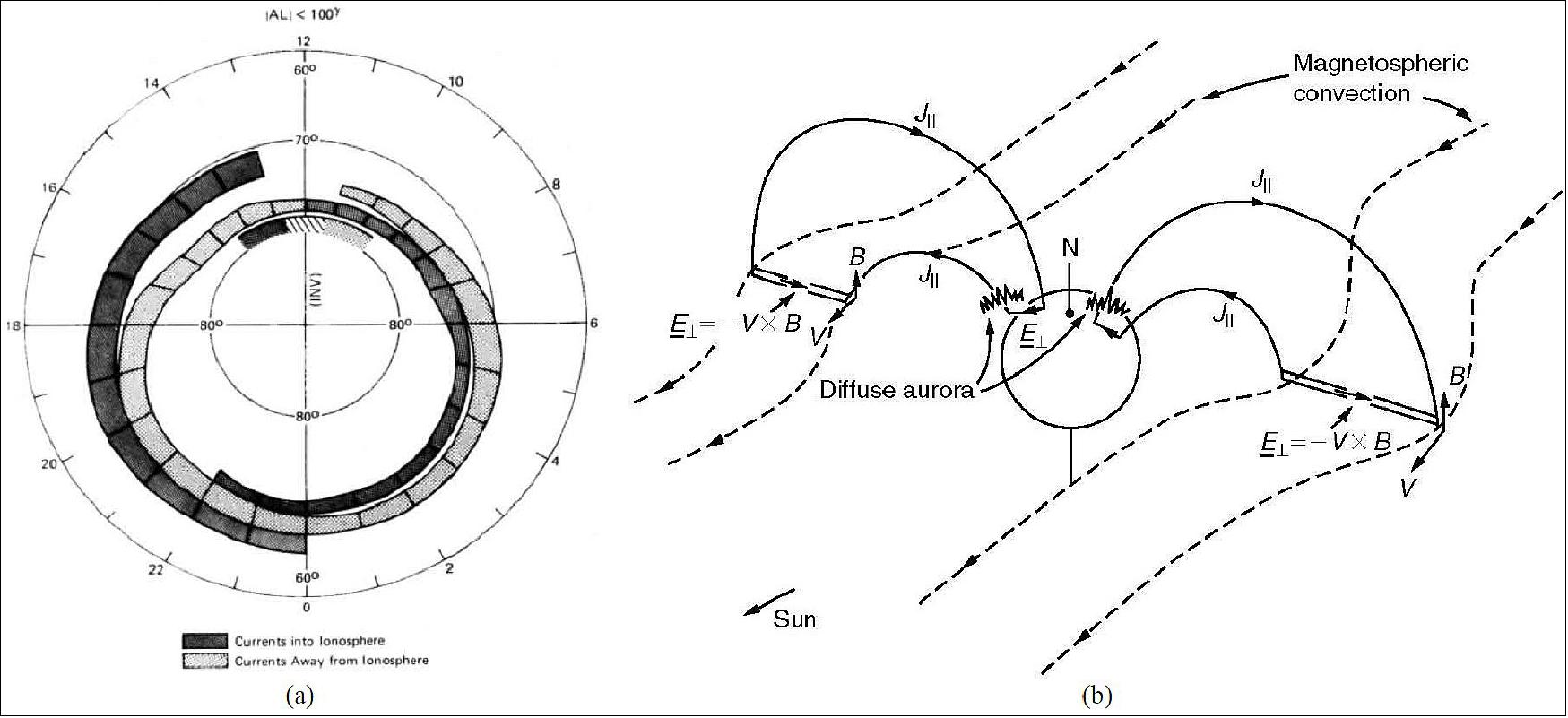
Auroras are a visible manifestation of the release of electromagnetic energy from the magnetosphere into the outer atmosphere. This energy flow is mediated by magnetic field-aligned currents (FACs) which close through the ionosphere in the altitude range of 120 to 180 km . Our modern understanding of the auroral current circuit has come from space-based sensors. While the main structure was postulated early in the 20th century (Birkeland, 1908) 2), direct observational evidence had to await the arrival of the space age, when magnetic sensors on polar orbiting satellites confirmed the presence of field-aligned currents that mediate the flow of energy between the magnetosphere and Earth’s outer atmosphere. Figure 1a shows an early statistical map of the Region 1 and Region 2 Birkeland currents derived from 493 passes of the TRIAD (Tri-Axial Attitude Determination) satellite of NASA over the northern polar region. The observed mean pattern is consistent with the conceptual model of Figure 1b (after Kelley, 2009) 3), where the collisional ionosphere acts as a resistive load for an Earthward directed “DC” Poynting flux. 4)
The AMPERE (Active Magnetosphere and Planetary Electrodynamics Response Experiment) enabled, for the first time, the construction of time-dependent images of the global Birkeland current system. 5) AMPERE leveraged the engineering-grade magnetometers on board the 66-element Iridium satellite constellation (6 orbital planes, 11 satellites per plane) as a space-based sensor network. Figure Figure 2a shows a “snapshot” of magnetic deflections (10 minute average) during the onset of a geomagnetic substorm near the west coast of Alaska. Figure 2b shows the corresponding field-aligned currents derived through spherical harmonic analysis of Ampere’s law. 6) The complete image sequence for this substorm event is included as supplemental material.
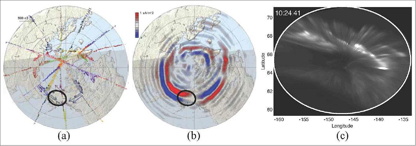
Although Figure 2b is generally consistent with the mean pattern of Figure 1, a gap in our empirical description becomes apparent when we attempt to reconcile this picture with observations of auroral dynamics from below. Figure 2c shows an all-sky image of the aurora (white light) within the ovular region in Figures 2b. Comparing Figures 2b and 2c suggests that the large-scale Poynting flux impinging the ionosphere is dissipated through small-scale current channels that, in turn, structure the conductivity field through impact ionization. 7)
Theory and observations have suggested Alfvén wave dispersion as the likely mechanism for the development of sub-kilometer sub-second variability in the auroral particle flux. 8) 9)
The mission, called ANDESITE (Ad-hoc Network Demonstration for Spatially Extended Satellite-based Inquiry and Other Team Endeavors), will eject eight free-flying vector magnetometers from a 6U CubeSat, forming a nine-element short-baseline (<50 km) mesh network in space. The measurements will be analyzed collaboratively with ground-based auroral imagery in an effort to resolve kilometer-scale variability in the overlying field-aligned currents.
Spacecraft
ANDESITE leverages many capabilities that have come about from commercial and academic interest in small satellite technology while ultimately remaining a very simple scientific approach: networked magnetometers. It is designed to the CubeSat standard, fitting in a “6U” form factor (20 cm x 30 cm x 10 cm) for the Planetary Systems Corporation Canisterized Satellite Dispenser (CSD). Relying on many commercially available subsystems for its operation, it has proven to be inexpensive (hardware cost of ~$100,000) when compared to larger multipoint sampling missions. The system is currently scheduled for launch on a mission of NASA’s Educational Launch of Nanosatellites (ELaNa) program (Ref. 1).
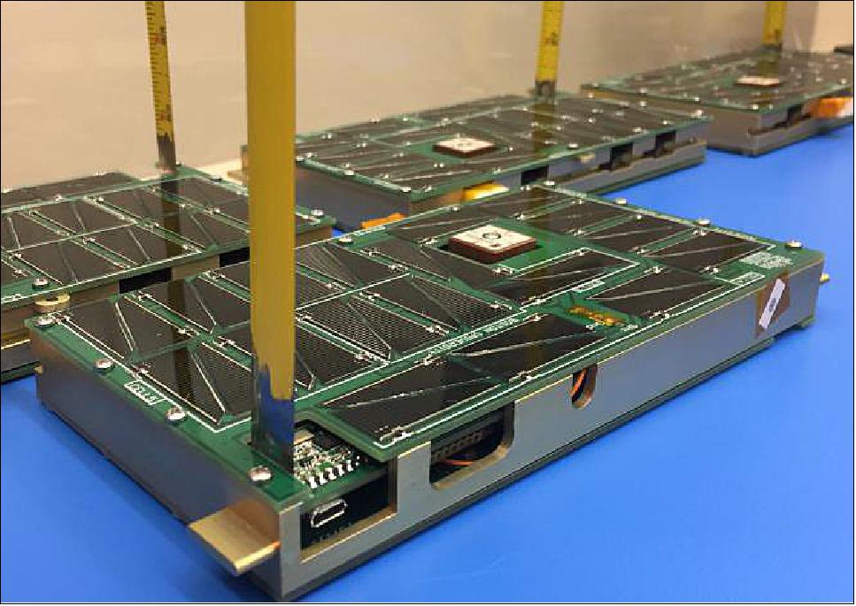
Once deployed from the launch vehicle, every few orbits, the main 6U spacecraft bus or “mule” (Figure 3) deploys pairs of smaller sensor nodes (Figure 4). These nodes each contain a three-axis magnetometer and relay their measurements back to the mule, which communicates the data to ground through the GlobalStar communication network via a NearSpace Launch EyeStar Duplex radio.

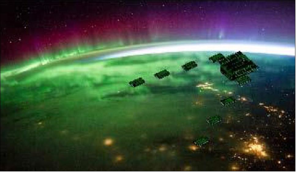
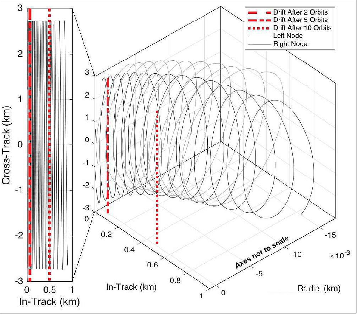
Due to different drag properties between the mule and the nodes, they slowly drift apart and create a spatial separation that allows sampling in- and cross-orbital track, as seen in an artist’s rendition in Figure 5. A more detailed relative orbit is shown in Figure 6, which was created using an orbital propagator that incorporated the NRLMSISE-00 atmosphere and a 70 x 70 degree/order gravity model. Coordinates in the figure are defined as: “In-Track,” aligned with the velocity direction; “Cross-Track,” aligned with direction of orbital momentum; and “Radial,” completing the right-handed system. Loss of orbital energy by the sensor nodes relative to the mule causes them to drift forward in the relative coordinates. Cross-Track separations are near the maximum in the polar regions, but In-Track separation exponentially expands, defining a mission lifetime based on the time until nodes drift out of communications (on the order of a week). During the mission, the resulting formation effectively combines the geometric concepts of SWARM. 10)
Near term, In-Track separation can be controlled by time of the node releases, which is adjustable on-orbit; a designed cross-track separation of 5 km is set by the spring constant of the ejection mechanism (Figure 6), but for this analysis, we will vary it to understand the limitations of the design choice. Our goal in the next sections is to characterize the sensor and parameterize the network’s geometry, thereby assessing the system’s relevance to scientific measurement.
Deployment Mechanism
The deployment mechanism has three crucial objectives: (1) deploy each pair of nodes on command, so as to guarantee appropriate formation on orbit; (2) do so without inducing a torque on the mule; and (3) ensure appropriate deployment velocity for ideal cross-track separation while traversing the Auroral region.
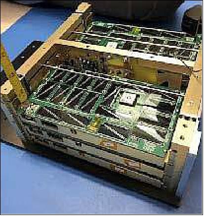
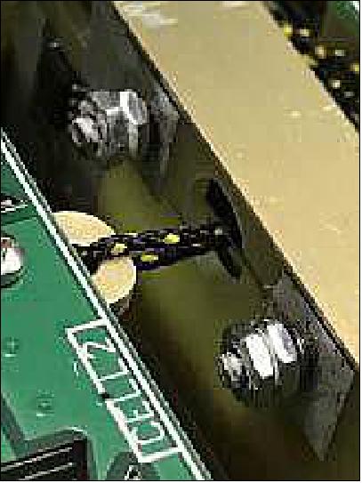
To meet these objectives, a spring-loaded burn-wire mechanism was developed and housed in the mule’s 4U payload bay. There is a slot on each sensor node rear that fits onto a steel rod, and the steel rods are attached on each end to 9.6 lb springs. When the nodes are in the payload bay (Figure 7), they are tied together using Vectran cord. Attached to a deployer circuit board are four loops of a nichrome wire (one per node pair), which wrap around the cord as seen in Figure 8. When a pair of nodes needs to be deployed, a current is run through the nichrome wire to burn the cord and activate the springs. The project verified on a microgravity flight in 2015 that each node ejects at ~3 m/s and the equal and opposite forces of the node deployment cancel to avoid torque on the mule.
Development Status
• March 15, 2020: TriSept Corporation (Chantilly, VA, USA) has completed the integration activity for NASA’s ELaNa 32 ANDESITE mission, a rideshare set to launch Boston University’s groundbreaking scientific study of the Earth’s magnetic field on a Rocket Lab Electron from New Zealand later this month. 11)
- The culmination of an eight-year collaborative research program among BU’s talented electrical and mechanical engineering students and professors, NASA’s CubeSat Launch Initiative (CSLI) will lift the university’s 6U CubeSat into LEO. Once in space, this smallsat will initiate measurements of the magnetosphere with onboard sensors, later releasing eight smallsats carrying small magnetometer sensors to track electric currents flowing in and out of the atmosphere.
- Josh Semeter, an electrical engineering professor with Boston University’s Center for Space Physics who first conceptualized the ANDESITE mission, said this mission with NASA will demonstrate how CubeSats can play a vital role in providing an unprecedented view into the variations of electrical activity racing through space and its impact on lives here on Earth.
- GPS services, for example, can be directly affected. If all goes as planned, the CubeSat will release eight smallsat sensors into space to form a first-of-its-kind, free-flying, mesh network capable of delivering uniquely comprehensive data mapping of magnetic fields and space weather to smart phones here on campus.
- Like many scientific missions, Boston University’s ANDESITE mission spacecraft and hardware will feature standard electronics components. The mission team estimates the network of satellite sensors, which will drift further apart in space during the experiment, will communicate and deliver data maps of the magnetic field and electric currents in the area for at least two to three weeks and possibly much longer.
- When it comes to the name of their mission, students and faculty jokingly claim ANDESITE is one of the longest acronyms they know – Adhoc Network Demonstration for Extended Satellite Inquiries and other Team Endeavors.
- Jason Armstrong, TriSept’s Director of Launch Integration Services, added that the company, the University spacecraft team and NASA have completed the initial integration of the ANDESITE mission by installing the CubeSat into the dispenser device and preparing the spacecraft for shipment to Rocket Lab in New Zealand. This is an especially gratifying mission that demonstrates what NASA’s ELaNa missions are all about – opening up space access to academia and other scientific groups that otherwise might not be able to fulfill their vision and allow their students to put their experiments to the ultimate test.”
- Brian Walsh, a mechanical engineering professor at Boston University who spearheaded the effort to secure the NASA rideshare, remarked that this incredible research and educational opportunity wouldn’t exist without NASA’s CubeSat Launch Initiative (CSLI), and students and programs would be left to speculate how their missions would perform in space. Long before this upcoming milestone mission launch, ANDESITE has helped to launch the careers of Boston University students who contributed countless hours to this breakthrough experiment. Many have gone on to head and support smallsat programs for some of the biggest government agencies and corporations leading the space industry today.
- Scott Higginbotham, NASA LSP ELaNa Mission Lead, noted that the agency recently celebrated the monumental deployment of the 100th CSLI selected CubeSat mission into space – and that’s amazing. Hundreds of students have benefited from the real-world hands-on experience that designing, building and launching a CubeSat provides. This initiative is a critical part of NASA’s efforts to engage with and prepare the next generation of space explorers, and the success and longevity of this program underscores that commitment.”
• December 2, 2019: TriSept Corp., a launch integration and mission management company, announced Dec. 2 an $18 million indefinite delivery indefinite quantity (IDIQ) contract to support NASA CubeSat launches. 12)
- Under the new contract, NASA will have the option of turning to TriSept of Chantilly, Virginia, for mission integration services and dispenser hardware in support of CubeSat launches through 2025.
- Under a previous IDIQ contract, TriSept integrated the ten CubeSats that launched in December 2018 on a Rocket Lab Electron launch vehicle as part of NASA’s 19th Educational Launch of Nanosatellites mission. TriSept also is integrating eleven CubeSats scheduled to travel into orbit on Virgin Orbit’s Launcher One rocket in 2020 as part of NASA’s 20th Educational Launch of Nanosatellites mission.
- In addition, TriSept is helping to integrate Ad-Hoc Network Demonstration for Extended Satellite-Based Inquiry and Other Team Endeavors, a CubeSat developed by Boston University’s Center for Space Physics and scheduled to launch in early 2020 on a Rocket Lab Electron.
- “TriSept is honored to have the opportunity to continue providing launch integration and hardware procurement support for NASA’s CubeSat launch support needs that continues opening the door to more space access and a growing number of important and diverse missions,” TriSept CEO Rob Spicer said in a statement. “Our experienced launch integration and management teams look forward to extending our collaborative relationship with NASA’s Launch Services Program and stand ready to help enable upcoming programs under this latest IDIQ contract.”
- TriSept, a 25-year-old company, has provided launch integration and program support on more than 200 satellites launched on 20 rockets from 13 launch sites around the world, the company said in a Dec. 2 news release.
Launch
The ANDESITE CubeSat was launched on 13 June 2020 (05:12 UTC) on an Electron vehicle of Rocket Lab's rideshare mission. The launch site was the Launch Complex 1 on Mahia Peninsula, New Zealand. 13) 14)
This rideshare mission has been named 'Don't Stop Me Now' in recognition of Rocket Lab board member and avid Queen fan Scott Smith, who recently passed away. Other payloads flown on the mission are three classified payloads designed, built and operated by the NRO (National Reconnaissance Office); and the M2 Pathfinder satellite, a collaboration between the UNSW Canberra Space and the Australian Government, to test communications architecture and other technologies.
The satellite launched as part of NASA’s CubeSat Launch Initiative (CSLI) to conduct groundbreaking scientific studies into Earth’s magnetic field. Once in space, the ANDESITE satellite will initiate measurements of the magnetosphere with onboard sensors, later releasing eight picosatellites carrying small magnetometer sensors to track electric currents flowing in and out of the atmosphere, a phenomenon also known as space weather.
Mission Status
Rocket Lab has postponed the launch of its next mission in response to the COVID-19 situation.
• March 24, 2019: In response to the evolving COVID-19 situation, we have paused launch preparations for our next mission to protect the health and safety of Rocket Lab team members, our families, and the wider community.
- The mission was scheduled to lift off from Launch Complex 1 in New Zealand on 30 March UTC. Launch preparations have been paused, however, following the New Zealand Government’s announcement on 23 March NZDT to implement the Level 4 COVID-19 response which requires most businesses to close and instructs people to stay at home. We commend the government for taking this drastic but necessary step to limit the spread of COVID-19.
- We have the full support of our customers in pausing operations and we are grateful for their understanding in these challenging times. We are working with the government, health officials, and our customers to determine when launch operations can resume. The launch vehicle and ground systems will remain in a state of readiness for launch as the evolving situation allows it. The majority of our team is working from home with the exception of a few essential personnel who are monitoring and maintaining critical systems.
- In recent years, we have placed an increased emphasis on delivering responsive launch capability for our customers, which means having launch vehicles and pads ready for rapid call-up launch capability. As a result of this approach, we’re fortunate to have enough launch vehicles ready that we can effectively manage a pause in production and still have vehicles available for launch as soon as conditions allow.
- In the days, weeks, and months to come, we’ll be following the advice of the government and health authorities to protect our teams in the United States and New Zealand.
- Our deepest thanks go to the medical professionals, scientists and researchers, supermarket workers, and all those providing essential services in these trying times. We are grateful for all that you do.
Further Payloads on the Rideshare Mission
• The mission also carries three classified payloads designed, built and operated by the NRO (National Reconnaissance Office). The mission was procured under the agency’s Rapid Acquisition of a Small Rocket (RASR) contract vehicle. RASR allows the NRO to explore new launch opportunities that provide a streamlined, commercial approach for getting small satellites into space, as well as provide those working in the small satellite community with timely and cost-effective access to space.
• The ANDESITE and NRO payloads will be joined on the mission by the M2 Pathfinder satellite, a collaboration between the University of New South Wales (UNSW) Canberra Space and the Australian Government. The M2 Pathfinder will test communications architecture and other technologies that will assist in informing the future space capabilities of Australia. The satellite will demonstrate the ability of an onboard software-based radio to operate and reconfigure while in orbit.
• Orbit: ANDESITE will be launched from the Rocket Labs New Zealand launch site ((Rocket Lab Launch Complex 1, also known as Mahia Launch Complex or Spaceport), into a Perigee / Apogee of 590 x 590 km orbit, at 97.8° inclination.
Sensor Complement
Magnetometers
The magnetometers chosen and mounted to the sensor node boards are the HMC1001 and HMC1002, 1-axis and 2-axis magnetic sensors, respectively. They are rugged, provide a range of ± 2 Gauss (± 200,000 nT), and have a stated resolution of 27 µGauss (2.7 nT) and linear temperature response over the expected environment. Self-noise characteristics of the sensor at the frequencies expected to be seen (0.1 to 10 Hz) falls several orders of magnitude below the sensitivity needed for the mission. The outputs of the magnetometers are connected to an analog low-pass filter and then fed into an a 24-bit ADC (Analog-to-Digital Converter).
To minimize the effect of ground loops, all ground planes are removed in the area around the magnetometers. All the power supply integrated circuits are placed as far away from the magnetic sensors and shielded with RF shields. The magnetometers are still in close proximity with shielded inductors from the solar panels, but testing has not shown strong interference.
The nodes also include an iNEMO inertial module from STMicroelectronics, along with an on-board SkyTraQ Venus GPS chip. The science data packet will include readouts of angular rates along with position information from these chips to allow for attitude estimates for each node to be performed a posteriori on the ground using similar mathematical methods. 16) With these methods, we aim to determine the vector components of the magnetic vector. The residual bias should have amplitude of about 200 nT and frequency outside the band in which we expect the scientifically relevant signal (Ref. 1).
Calibration
An understanding of our on-orbit measurements is achieved by calibration of the node system as built. More thorough calibration using similar magnetometers has previously been done to show that about 3 nT resolution on an extended boom is possible. 17) Here, we present a brief characterization to illustrate the implementation in our system where the magnetometer is within the spacecraft.
For the testing of the payload magnetometers, we use a precision-controlled 1.2 meter Helmholtz cage. Within the cage, a non-magnetic test stand keeps the sensor node in alignment as various external fields are commanded. To characterize each axis, we command the coils along the three body axes of the spacecraft sweeping from –60,000 nT to + 60,000 nT in uniform incremental steps. Holding field for two seconds, we sample with the node at a rate of 30 Hz, giving a window of around 50 data points where the cage has settled. Between each step, we zero the cage and let it settle for two seconds and check for hysteresis of the measurements.
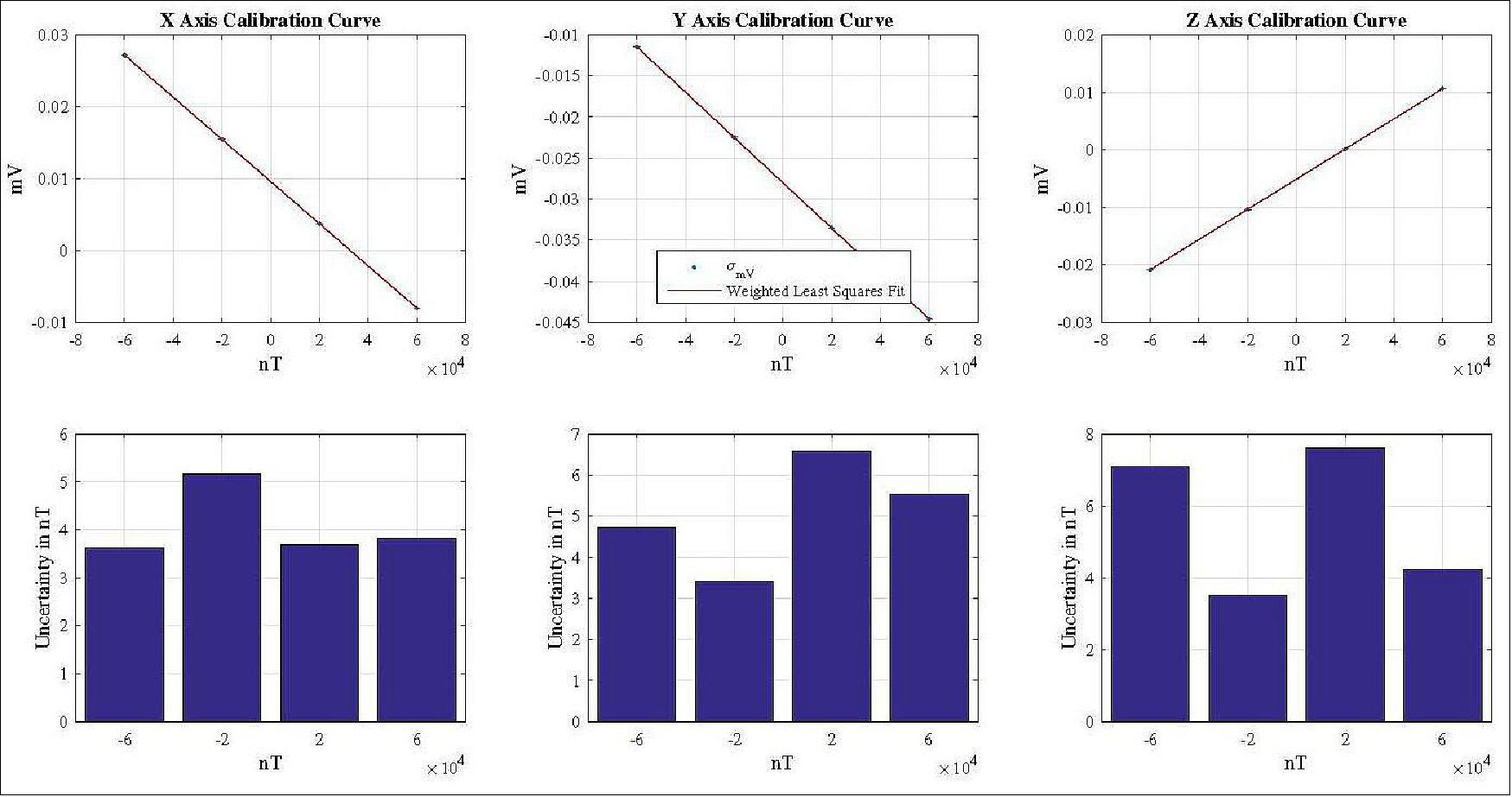
With the mean measured output of the node in mV, the controlled magnetic field from the cage in nT, and the standard deviation about the mean output (used as the weighting), we perform a weighted least squares fit in the spacecraft body frame: positive x-axis along the long axis of the sensor node and positive z-axis in the nadir direction. The results of these calibration fits and the associated uncertainties calculated for each axis at each commanded field are shown in Figure 9. Magnetometer calibration is shown for each principle coordinate of the sensor node body axes (top plots of the figure). The bottom plots show the associated instrument uncertainty converted from the ADC (Analog-to-Digital-Converter) outputs in mV to nT using the calibration slope, referenced as sensitivity in magnetometer literature, and plotted against the commanded test field strength. For all these plots, the x-axis is the Helmholtz cage’s commanded field strength. Note in this test, each axis is able to sample with a precision less than 10 nT.
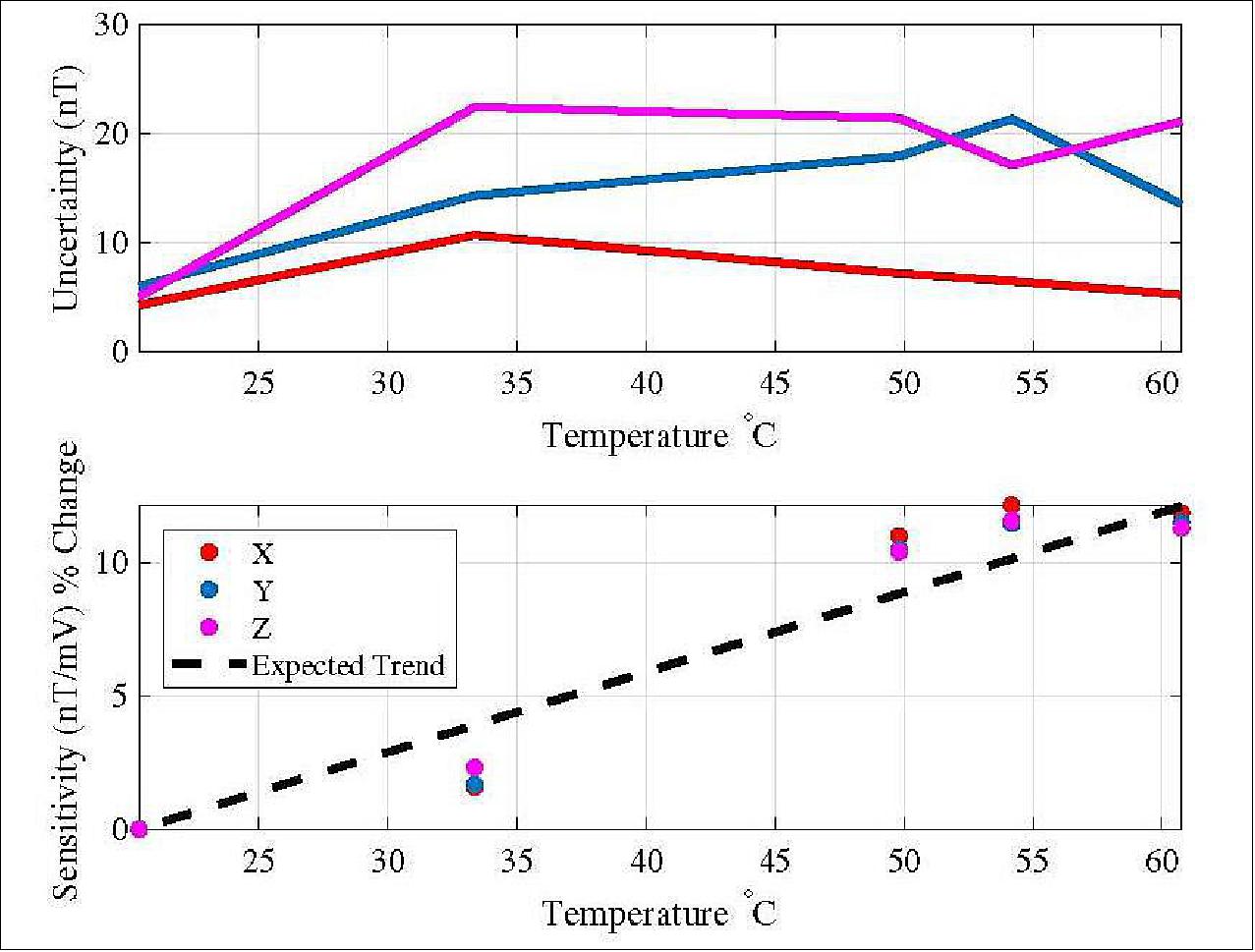
We also performed a temperature sensitivity test where we heated a node using a thermal pad and collected data with the same calibration routine. The results compare favorably to the stated capabilities of the Honeywell sensor, as seen in Figure 10. The sensors are well within the performance specs needed to do the spatial correlation of magnetic structures that we may see, since our main goal is a relative measurement of the field between nodes, and all nodes should remain at a steady temperature due to the large thermal capacitance of the node aluminum structure.
References
1) J. Brent Parham, Maria Kromis, David Einhorn, Phillip Teng, Sergei Posnov, Hannah Levin, Osi Van Dessel, Aleks Zosuls, Brian Walsh, and Joshua Semeter, ”Networked Small Satellite Magnetometers for Auroral Plasma Science,” JoSS (Journal of Small Satellites), Vol. 8, No. 1, pp. 801–814, 2019, URL: https://jossonline.com/wp-content/uploads/2019/05/Final-Parham-Networked-Small-
Satellite-Magnetometers-for-Auroral-Plasma-Science-PayloadScienceMissions.pdf
2) Kristian Birkeland, ”The Norwegian Aurora Polaris Expedition 1902-1903,” Book, Section 1 published 1908; Plasma-Universe.com, https://www.plasma-universe.com
/the-norwegian-aurora-polaris-expedition-1902-1903-book/
3) Michael Kelley, ” The Earth's Ionosphere, Volume 96, 2nd Edition, Hardcover ISBN: 9780120884254, eBook ISBN: 9780080916576, Academic Press, Published:5 May 2009, URL: https://www.elsevier.com/books/the-earths-ionosphere/kelley/978-0-12-088425-4
4) T. Iijima and T. Potemra, ”Field-Aligned Currents in the Dayside Cusp Observed by Triad,” . Journal of Geophysical Research, Vol. 81(34), pp. 5971–5979, Published 1 December 1976, https://doi.org/10.1029/JA081i034p05971
5) L. B. N. Clausen, J. B. H. Baker, J. M. Ruohoniemi, S. E. Milan, B. J. Anderson, ”Dynamics of the region 1 Birkeland current oval derived from the Active Magnetosphere and Planetary Electrodynamics Response Experiment (AMPERE),” Journal of Geophysical Research, Volume 117, A06233, Published: 30 June 2012, https://doi.org/10.1029/2012JA017666, URL: https://agupubs.onlinelibrary.wiley.com/doi/epdf/10.1029/2012JA017666
6) C. L. Waters, B. J. Anderson, K. Liou, ”Estimation of global field aligned currents using the iridium® System magnetometer data,” Geophysical Research Letters, Volume28, Issue11, Published: 1 June 2001,Pages 2165-2168, https://doi.org/10.1029/2000GL012725, URL: https://agupubs.onlinelibrary.wiley.com/doi/epdf/10.1029/2000GL012725
7) J. Semeter, C. J. Heinselman, G. G. Sivjee, et al. (2005): ”Ionospheric Response to Wave-Accelerated Electrons at the Poleward Auroral Boundary,” Journal of Geophysical Research: Space Physics, Vol. 110 (A11)
8) J. Semeter, E. M. Blixt, ”Evidence for Alfvén Wave Dispersion Identified in High-Resolution Auroral Imagery,” Geophysical Research Letters, Volume33, Issue13, July 2006, https://doi.org/10.1029/2006GL026274, URL: https://agupubs.onlinelibrary.wiley.com/doi/epdf/10.1029/2006GL026274
9) H. Dahlgren, J. L. Semeter, R. A. Marshall, et al. (2013): ”The Optical Manifestation of Dispersive Field-Aligned Bursts in Auroral Breakup Arcs,” Journal of Geophysical Research: Space Physics, Vol. 118(7), pp. 4572–4582
10) Patricia Ritter, Hermann Lühr, ”Curl-B technique applied to Swarm constellation for determining field-aligned currents,” Earth, Planets and Space, Volume 58, pages463–476(2006),
11) ”ANDESITE Mission Integration Completed by TriSept,” Satnews Daily, 15 March 2020, URL: https://www.satnews.com/story.php?number=1027108460
12) Debra Werner, ”NASA taps TriSept for ongoing cubesat launch support,” SpaceNews, 2 December 2019, URL: https://spacenews.com/trisept-nasa-cubesats/
13) ”Rocket Lab's Successful 12th Electron Mission Launch for NASA, NRO and UNSW Canberra,” Satnews Daily, 13 June 2020, URL: http://www.satnews.com/story.php?number=1551152696
14) Stephen Clark, ”University-built CubeSat launched with swarm of auroral science nodes,” Spaceflight Now, 13 June 2020, URL: https://spaceflightnow.com/2020/06/13
/university-built-cubesat-launched-with-swarm-of-auroral-science-nodes/
15) ”COVID-19 Update: Rocket Lab has postponed the launch of its next mission in response to the COVID-19 situation,” Rocket Lab, 24 March 2020, URL: https://www.rocketlabusa.com/news/updates/covid-19-
update-rocket-lab-has-postponed-the-launch-of-its-next-mission-in-response-to-the-covid-19-situation/
16) John L. Crassidis, Kok-Lam Lai and Richard R. Harman, ”Real-Time Attitude-Independent Three-Axis Magnetometer Calibration,”Journal of Guidance, Control, and Dynamics, Volume 28, No 1, January-February 2005, Published online: 23 May 2012, https://doi.org/10.2514/1.6278
17) P. Brown, B. J. Whiteside, T. J. Beek, P. Fox, T. S. Horbury, T. M. Oddy, M. O. Archer, J. P. Eastwood, D. Sanz-Hernández, J. G. Sample, E. Cupido, H. O’Brien, and C. M. Carr, ”Space magnetometer based on an anisotropic magnetoresistive hybrid sensor,” Review of Scientific Instruments, Volume 85, 125117 (2014), https://doi.org/10.1063/1.4904702