AprizeSat-3 and -4
EO
Ocean
Multi-purpose imagery (ocean)
Mission complete
Quick facts
Overview
| Mission type | EO |
| Mission status | Mission complete |
| Launch date | 29 Jul 2009 |
| End of life date | 29 Jul 2019 |
| Measurement domain | Ocean |
| Measurement category | Multi-purpose imagery (ocean), Ocean topography/currents, Ocean surface winds, Ocean wave height and spectrum |
| Measurement detailed | Sea level, Visibility |
| Instruments | Communications payload (Ka and UHF band), GPS receiver |
| Instrument type | Other, Communications |
AprizeSat-3 and -4
AprizeSat-3 and -4 are two microsatellites of Aprize Satellite Inc. of Fairfax, VA, USA built by SpaceQuest Ltd. of Fairfax, VA. The objective is to demonstrate AIS (Automatic Identification System) instrument technology for the detection of ships on the oceans. SpaceQuest, Ltd. is the technology arm of Aprize Satellite Inc., a provider of low-cost wireless services for worldwide asset tracking and data monitoring. 1) 2) 3) 4)
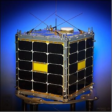
SpaceQuest completed the construction and launch of two AIS satellites in 10-months (start of construction in Sept. 2008, integration of flight trays and functional tests in June 2009).
Spacecraft
Structure
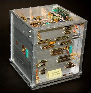
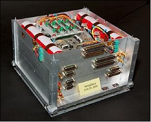
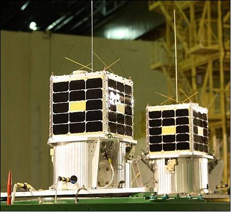
Each microsatellite is a cube of 25 cm sidelength with a mass of 13 kg and with a design life of 10 years developed at SpaceQuest Ltd. The spacecraft structure is based on SpaceQuest’s standard Microsat design consisting of stacked aluminum trays forming a cube of 25 cm sidelength (Figure 2). The trays are aligned with pins and tied together with four threaded-rod assemblies at the four corners. Most harness wiring and connectors exist on a single side defined as the “chimney.” Sheet metal side panels with integrated solar panels and antennae cover each of the six sides. Conical stainless steel feet provide a forgiving, but secure interface to the launch adapter structure and simple chamfers near the base of the structure provide a surface for the release mechanism to apply a retaining normal force until release.
SpaceQuest has used a variant of this structure for over a decade in more than 12 satellites. Successful launches on multiple launch vehicles have borne out the validity and robustness of the design.
EPS (Electrical Power Subsystem)
The spacecraft each have six body-mounted solar panels. The four side panels each consist of a 15 W panel, with two strings of seven UTJ (Ultra Triple Junction) GaAs of 28.3% efficient solar cells. The top and bottom panels each consist of a single string, producing 7.7 W each.
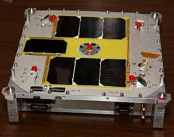
A peak-power-tracking BCR (Battery Charge Regulator) board ensures maximum utilization of the solar panels, while charging the 4Ah battery and protecting it from overcharge and cell-reversal. The BCR also provides essential services such as load-shedding in a low power condition and flight computer reset at lower, more dangerous power levels. The BCR provides regulated 3.3 V and 5 V supplies in addition to unregulated 8 V from the solar panels when in the sun. The peak-power-tracker is configured via a serial port to optimize utilization of the solar panels as they age. The BCR also provides power system telemetry.
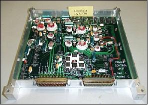
Six NiCd batteries are strung in series to form an 8 V unregulated power bus. Temperature and voltage measurements of the battery are fed back to the BCR to ensure proper conditioning and charging of the NiCd cells. A power distribution board provides additional, switched regulated power supplies to other subsystems and components. Switched, regulated 3.3, 5 and 12 V supplies are available in addition to unregulated 8 V battery voltage. Power telemetry and alarms provide fine-grained control to the flight computer.
ACS (Attitude Control Subsystem)
The satellites employ passive magnetic attitude stabilization. Rare Earth, Neodymium magnets are fixed inside the spacecraft structure. These magnets work to align with the Earth's magnetic field in orbit, inducing a corrective torque on the spacecraft. In time, the spacecraft assumes a damped rotation of two revolutions per orbit.
Alternating strips of reflective and non-reflective tape on the corners of the spacecraft produce a radiometer effect, inducing a slow roll which serves to evenly distribute the heat from the Sun across the spacecraft. Recent measurements showed the roll rate is approximately ¼ rpm.
Long, thin non-permeable iron rods act as magnetic hysteresis rods. Two orthogonal sets are arranged in the plane of the spin axis of the spacecraft and serve to limit the spin rate.
C&DH (Command & Data Handling) Subsystem
Primary command and data handling is performed by the IFC-1000 (Integrated Flight Computer). The IFC is a standard SpaceQuest product that includes extensive flight heritage. At the IFC's core is a V53, 8086 processor. Several integrated FPGAs, and GMSK modems serve to distinguish the IFC as a primary communications computer.
A 16 MB RAM disk provides on-board data storage. Active programs and memory are stored in triple modular redundancy EDAC (Error Detection and Correction) memory. A flash drive provides non-volatile, radiation-tolerant storage for program binaries during reset or powered-down conditions. Finally, redundant ROM carries the boot loader, to which the spacecraft defaults on reset. All memory described above is integrated to the IFC itself.
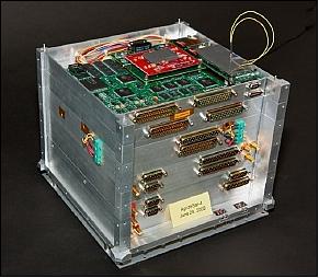
An ARM-7 microprocessor is included., which could replace the IFC-1000 in future designs. The ARM-7 board includes an experimental magnetic RAM which holds its memory in a powered-down state and is reported to be radiation hardened. This experiment has yet to be tested fully.
The Q5 high-performance payload computer is a third-generation design which combines a PowerPC and two radiation-tolerant FPGAs. The Q5 includes two large, integrated compact flash cards, which serve as redundant data and program storage. The Q5 also includes an integrated daughter-board, which adds analog-to-digital and digital-to-analog converters that interface with the Q5 itself. This provides an important recording capability which is used to return high-fidelity recordings of AIS traffic, etc. from orbit.
RF Communications
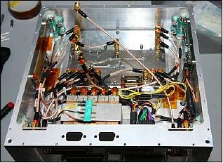
The primary command communications system is comprised of an always-on VHF command receiver and a pair of redundant UHF command and telemetry transceivers. Both the VHF uplink and UHF downlink can be commanded to a variety of baud rates ranging from 1.2 - 38.8 kbit/s. Normal operation is conducted at 9.6 kbit/s. SpaceQuest implemented a GMSK (Gaussian Minimum Shift Keying) modulation scheme, which makes optimal use of bandwidth and spectrum. The VHF and UHFs links are both GMSK modulated.
All communications payloads share common, monolithic LNAs (Low Noise Amplifiers) and T/R (Transmit / Receive) switching protection circuits. The LNAs and T/R switching chains are specific to the various frequency band implemented in the spacecraft. A separate RF crossover switch is also implemented as a hedge against loss of one of the redundant UHF command and telemetry transceivers, but is not used in normal operation.
Four small UHF receivers are used for M2M (Machine-to-Machine) payload data reception. They are connected to four polarized antennas by way of a hybrid combiner. This arrangement defines a circular antenna, which is capable of receiving data from the vertically polarized whip antennae on each of the ground-based Tags regardless of the spacecraft or Tag orientation. The UHF command and telemetry transceivers also share this antenna for convenience, though the SpaceQuest ground stations all have circular UHF Yagi antennae.
An experimental UHF receiver/modem (RX-450M) is also implemented. Its primary purpose is space qualification. However, it is also used for secondary communications to several non-essential experiments and payloads.
A full duplex S-band receiver and transmitter sharing a circular antenna are also integrated to each satellite. The S-band transmitter is capable of data rates up to several Mbit/s. The S-band transmitter and receiver are connected to various sources and sinks aboard the spacecraft via an intermediate frequency (IF) bus as well as via a serial data bus. The 1W S-band transmitter consumes less power than the 6 W UHF transmitter. This benefit, combined with the increased bit rate, makes the S-band communication subsystem an ideal gateway for large payload data requirements.
A pair of custom-designed, very sensitive VHF receivers implements the RF front-end of the on-board AIS payload. Each receiver is tuned to a specific channel of the two-channel AIS system.
Two other communications-related systems include a space-qualified GPS receiver and an experimental stand-alone Radio Reset Modem (RRM-450), which can selectively reset payloads or the entire spacecraft.
Launch
The Aprize-3 and -4 microsatellites were launched as secondary payloads on July 29, 2009 from Baikonur Cosmodrome, Kazakhstan. The launch service provider was ISC Kosmotras of Moscow. 5) 6)
The primary payload on this Dnepr vehicle launch was DubaiSat-1 of UAE (United Arab Emirates). Further secondary payloads were: Deimos-1 (Spain) and UK-DMC-2 (SSTL, UK), and NanoSat-1B (INTA, Spain).
Orbit: Sun-synchronous near-circular orbit, altitude = 686 km, inclination = 98.13º, the orbital period is about 97.7 minutes, the LTAN (Local Time on Ascending Node) is at 10:30 hours.
Mission Status
• AprizeSat-3 and -4 are operating nominally in 2011.
• AprizeSat-3 and -4 are operating nominally in 2010. The two spacecraft are collecting some 460,000 AIS transmissions from about 22,000 ships each day. 7)
Most recently, with the availability of a large antenna dish, AprizeSat-3 and AprizeSat-4 have been able to switch to a high speed downlink. The spacecraft are now capable of continuously recording and downloading decoded AIS data up to 300 kbit/s. This eliminates the need for region-based recordings and filtering. Additional high-speed Earth stations will be brought online further reducing latency.
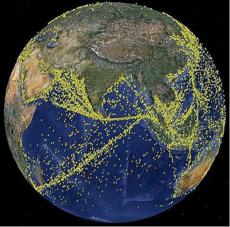
• The AprizeSat-3 and -4 are operating nominally in the fall 2009.
• Follow-up AIS activities:
- Analog transponder mode: Received two-channel AIS signal; download on S-band
- Digital storage mode: Digitize and store AIS raw data on-board; download on UHF
- Receive and store: Receive, process, decode and store; download later on UHF.
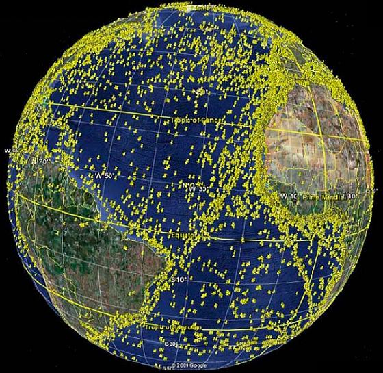
• AprizeSat-3 and -4 were commissioned 1 hour after separation. Both AIS payloads were activated and began collecting data on their second orbit. Over 200,000 AIS transmissions were captured and decoded in the first 160 minutes (Ref. 8).
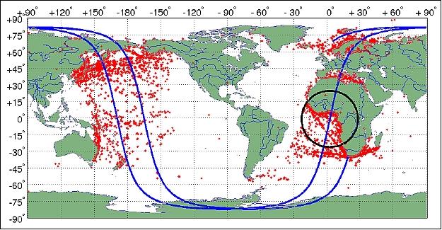
AprizeSats-3 and 4 have been collecting AIS messages nearly continuously since shortly after launch. The first recording started just minutes after separation from the upper stage. Several orbits later, during the first pass over the SpaceQuest, VA ground station in Virginia, the SpaceQuest team was able to download some of the data collected – in total, almost two orbits worth from each satellite (Ref. 4).
Sensor Complement
AIS (Automatic Identification System)
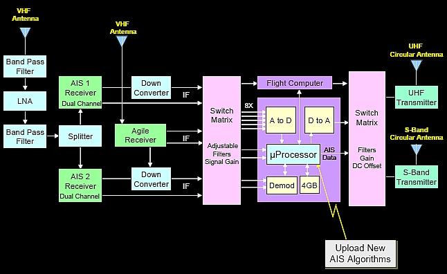
The AIS payload consists of the following elements (Ref. 1):
• 2 AIS monopole antennas
• 2 dual-channel AIS receivers with -125 dBm sensitivity
• 1 frequency-agile AIS receiver with -120 dBm sensitivity
• 1 frequency-agile 1 W S-band transmitter with a data rate of up to 500 kbit/s
• 2 UHF frequency-agile, 2 to 4 W transmitters with data rates of up to 38.8 kbit/s
• 2 independent AIS µprocessor recorders with 5 GB of data storage capacity
• 1 dual-channel down-converter with mixing and converting to various IF’s or baseband
• 1 audio switching matrix to switch any input to any output with gain & filter controls
• 1 14-channel GPS receiver for precise location and time
Processing Modes
- Digitize and store both AIS Channels using the ARM-7 or Power PC
- Decode AIS signals in real-time or post-process later
- Transpond raw analog signals or download digitized data using UHF or S-band
- Upload new processing algorithms as required.
Download Modes
- Real-time or S&F (Store-and-Forward)
- Analog or digital data
- Raw AIS signals or decoded data
- Download AIS data using: a) High-speed UHF transmitter or, b) S-band transmitter with data rates uo to 500 kbit/s.
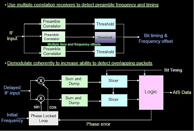
AIS decode and S&F: The S&F mode of AIS operations is the standard mode of operation. Reduced to its most basic functions, when the AIS payload is turned on, received messages are decoded time-stamped with their arrival along with other information, and stored on board the satellite. When a ground station initiates communications the satellite may be commanded to download the AIS data at high priority. In general, initial operations were conducted with the UHF downlink.
Operationally, the spacecraft have several different variants of store-and-forward operation.
1) MMSI (Maritime Mobile Service Identity) - Filtered S&F
The customer requirements and early ground station limitations, combined with the vast size of available payload data necessitated a culling of stored AIS data to obtain only the most relevant data for later download. One such algorithm is the MMSI filter, which uniquely identifies the transmitting entity. By decoding each received message and comparing the sender's MMSI to a list of desired entities (in general, ships), the on-board processors could eliminate all but the desired vessels, thereby reducing storage issues and downlink congestion and latency.
Examples of actual filters used include: cargo-type fleets (i.e. crude oil, liquid natural gas bulk cargo, etc.). Other filters include: flag country of vessel registration, country of vessel ownership and more.
The decimation of AIS messages implemented by this algorithm allowed full-Earth, 24/7 operation of the AIS payload, even before implementation of the high-speed S-band downlink. The MMSI-Filtered mode was also used in parallel with the Region-based mode.
2) Region-based S&F
The initial ground stations were limited to low-speed UHF downlink, which prohibited whole-Earth AIS data collection and downlink in a timely manner. Therefore, it was decided to limit unfiltered collection of AIS messages to regions of interest. The AIS payload was scheduled to record data on a time-based schedule established by ground computers and uploaded to the spacecraft, or by use of the on-board GPS receiver. In either case, certain geographic regions are chosen due to their geopolitical or commercial value and AIS messages are only collected when the satellites are passing over these regions. In this manner, SpaceQuest was able to respond to customer and government requests for unfiltered AIS data anywhere in the world with low latency and fast turnaround even before implementation of S-band operations.
3) Whole-Earth Coverage Using S-band Downlink
An S-band ground station was activated to establish a higher-speed communications link for data transmission. The S-band downlink can be as much as 32 times faster than the 9.6 kbit/s UHF downlink. The AIS payload can be left on constantly, collecting data for the entire Earth twice a day, due to the nature of its sun-synchronous orbit. This became the standard operating mode for the spacecraft in early 2010.
4) AIS Analog Recording
The Aprize satellites are capable of producing analog recordings of AIS message traffic on either channel or both, simultaneously. The recordings can then be “played back” on either the UHF or S-band frequencies. The advantage of recording and transmitting the AIS signal samples in analog as opposed to digital is that the samples can be transmitted with far less bandwidth as analog signals, reducing antenna size and power requirements. There is also an additional quantization error avoided by not using a digital playback.
5) AIS Analog Loopback
The analog loopback mode is similar to the analog recording mode. The difference is that the recordings are never stored on the satellite. Therefore, this mode is only used when a satellite is in contact with a ground station. The AIS receiver output, mixed to an IF can be connected to a UHF or S-band transmitter, relaying the AIS traffic to the ground in real time. Ground-based recorders or decoders can then interpret the data in real time or store it for later analysis.
M2M (Machine-to-Machine) Receiver
The AprizeSat spacecraft have a dual-purpose mission: AIS and M2M. Both missions can be performed in tandem, without interfering with the other. The AprizeSat spacecraft are equipped with low-power UHF receivers and transmitters that communicate with ground-based asset-tracking “Tags.” The Tags include a microprocessor, UHF transceiver, sensor interface, and long life battery. Various sensors inputs and/or outputs are integrated depending on the application, and an integrated GPS receiver is optional (Ref. 4).
A Tag can be placed anywhere in the world to monitor or control remote systems. Some applications include:
6) Pipeline cathodic protection
7) Cargo tracking
8) Propane tank fuel level measurement.
The sun-synchronous orbit guarantees global coverage at least twice per day, ensuring that the satellite constellation can collect, store, and forward telemetry from ground-based Tags worldwide.
Space Qualification of Components
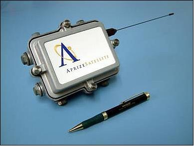
Each AprizeSat spacecraft includes several components or subsystems for space qualification. AprizeSat-3 and AprizeSat-4 are no exception. Among the new component being space-qualified are:
• ARM-7 flight computer
• Updated GPS receiver
• S-band receiver
• Advanced UHF transceiver
• Radio reset modem
• Multi-band receiver
• UHF circular antenna system.
References
1) Dino Lorenzini, Mark Kanawati, “TEXAS (Technical eXchange on AIS via Satellite) III Presentation,” Aug. 19, 2009, URL: http://www.spacequest.com/Articles/SpaceQuest-TEXAS-III-Presentation.pdf
3) Dino Lorenzini, Mark Kanawati, “TEXAS (Technical eXchange on AIS via Satellite) II,” Sept. 3, 2008, URL: http://www.dtic.mil/cgi-bin/GetTRDoc?AD=ADA513779&Location=U2&doc=GetTRDoc.pdf
4) Dino A. Lorenzini, Daniel E. CaJacob, “Rapid Construction, Launch, and On-Orbit Operation of Two AIS Satellites,” Proceedings of the 8th Responsive Space Conference, Los Angeles, CA, USA, March 8-11, 2010, URL: http://ais.spacequest.com/sites/ais.spacequest.com/files/RS8-Paper.pdf
5) SpaceQuest-Built Satellites Successfully Launched on Russian Dnepr Launch Vehicle,” URL: http://www.spacequest.com/Articles/Satellite...
6) “SpaceQuest-Built Satellites Successfully Launched On Russian Dnepr Launch Vehicle,” Space Daily, July 30, 2009, URL: http://www.spacedaily.com/reports/Spacequest_Built_Satellites...
7) Turner Brinton, “Space Hardware Firm Doubles Down on Ship Tracking Service,” Space News, April 19, 2010, p. 14
8) http://www.gmsa.gov/twiki/pub/Main/TexasIII/SpaceQuest_AIS_Texas_III_Presentation.pdf
The information compiled and edited in this article was provided by Herbert J. Kramer from his documentation of: ”Observation of the Earth and Its Environment: Survey of Missions and Sensors” (Springer Verlag) as well as many other sources after the publication of the 4th edition in 2002. - Comments and corrections to this article are always welcome for further updates (eoportal@symbios.space).