CBERS-1 and 2 (China-Brazil Earth Resources Satellite)
EO
Mission complete
Imaging multi-spectral radiometers (vis/IR)
High resolution optical imagers
China Brazil Earth Resources Satellite (CBERS) is a cooperative research agreement between the Chinese Academy of Space Technology (CAST) and the Brazilian Instituto de Pesquisas Espaciais (INPE). The first generation of the program was signed in July 1998, aiming to supply both countries with multispectral imagery. The initial satellite in the program, ZY-1 FM1 (Zi Yuan-1 Flight Model 1) was originally launched by CAST five years prior to the CBERS agreement but was subsequently renamed to CBERS-1. CBERS-2 was launched in October 2003 and the third mission, CBERS-2b, was launched in September 2007.
Quick facts
Overview
| Mission type | EO |
| Agency | CRESDA, INPE |
| Mission status | Mission complete |
| Launch date | 14 Oct 1999 |
| End of life date | 16 Apr 2010 |
| Measurement domain | Land |
| Measurement category | Multi-purpose imagery (land), Surface temperature (land), Vegetation, Albedo and reflectance |
| Measurement detailed | Land surface imagery, Vegetation type, Earth surface albedo, Land surface temperature |
| Instruments | DCS, HRC, IR-MSS, CCD, WFI |
| Instrument type | Imaging multi-spectral radiometers (vis/IR), High resolution optical imagers, Data collection |
| CEOS EO Handbook | See CBERS-1 and 2 (China-Brazil Earth Resources Satellite) summary |

Summary
Mission Capabilities
The primary instrument onboard CBERS satellites was the HRCC (High Resolution CCD Camera). Developed by the Beijing Institute of Space Machines and Electricity (BISME), the multispectral pushbroom camera was designed to capture high resolution images. CBERS missions also carried a whiskbroom Infrared Multispectral Scanner (IRMSS) on board, operating as an optomechanical system. Radiation entering the IRMSS was divided into three parts by relay optics, allowing for analysis in three focal planes: panchromatic (PAN), short-wave infrared (SWIR) and thermal infrared (TIR).
INPE also designed a complementary sensor for the HRCC, namely the Wide-field imager (WFI). The camera served to acquire low-resolution, wide-swath images, resulting in more synoptic views. Finally, the onboard data collection system (DCS) contained a space environment monitor (SEM). The primary purpose of the SEM is the detection of high energy radiation, utilising an aurora particle detector (APD). and a particle radiation detector (PRD).
Performance Specifications
HRCC has an effective spatial resolution of 19.5 m at nadir, equating to a Field Of View (FOV) of 8.4º. The revisit time for HRCC imaging was 26 days, owing to a small swath width of 113 km. The camera captured images across five spectral bands, with wavelengths ranging from 510 to 890 nm. The Infrared Spectrometer captured at a lower spatial resolution of 80 m and a swath width of 120 km.
WFI acted to produce images of lower spatial resolution (260 km). However, owing to its increased swath width and FOV, 890 km and 60º respectively, the temporal resolution is much higher, revisiting the same location every three to five days. WFI images across two spectral bands, ranging over 630 - 690 nm and 760 - 900 nm.
All satellites in the CEBRS program move in a sun-synchronous orbit, travelling at an altitude of 778 km and inclination of 98.5º.
Space and Hardware Components
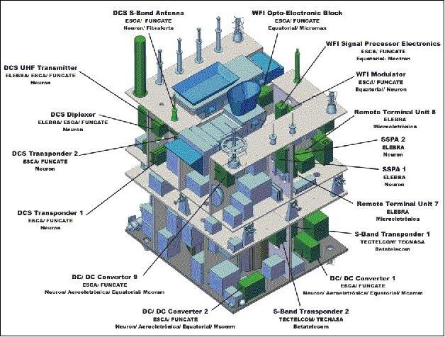
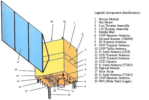
The CBERS spacecraft were composed of two modules, a payload and a service module. The payload module housed the optical and electronic systems, central to the HRCC, IRMSS and WFI instruments. The service module housed the power generation core, control systems, and telecommunication function. The total satellite mass is 1450 kg while the solar extendable solar panels produce 1100 W of power.
Radio frequency communication is used to transmit data, with all downlink transmission of image files conducted over the X-band and all uplink over the S-band. With a design life of two years, the CBERS-2B mission was retired in May 2010 due to an onboard power shortage/failure.
CBERS-1 (China-Brazil Earth Resources Satellite) - 1st Generation Satellite Series
Overview
CBERS is a cooperative program between CAST (Chinese Academy of Space Technology) of the People's Republic of China, and INPE (Instituto de Pesquisas Espaciais) of Brazil (government agreement of both countries for the development and operation of two satellites). The program was signed in July 1988 to establish a complete remote sensing system (space and ground segment) to supply both countries with multispectral remotely sensed imagery. - Prior to the international cooperative program of CBERS, there existed already a Chinese program, referred to as Zi Yuan or simply ZY, meaning resource in Chinese. The satellite ZY-1 FM1 (Zi Yuan-1 Flight Model 1) of this 1st generation program came to be known as CBERS-1. 1) 2) 3) 4) 5) 6) 7) 8)
Overall objectives: Observation and monitoring of the Earth's resources and environment with a multi-sensor imaging payload providing different spatial resolutions.
Spacecraft | Launch Date | Comment |
CBERS-1 | Oct. 14, 1999 | The spacecraft operated until Aug. 2003 |
CBERS-2 | Oct. 21, 2003 | The spacecraft was retired in late 2007 when imagery from CBERS-2B was available |
CBERS-2B | Sept. 19, 2007 | The spacecraft is operational in 2010 — but was retired on May 10, 2010 due to a power failure. |
2nd generation CBERS satellite series | ||
CBERS-3 | 2012 scheduled | In Feb. 2010, Brazil and China agreed to postpone the launch of CBERS-3 from 2010 to 2011. Ref. 9) |
CBERS-4 | 2013 planned |
|
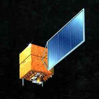
Spacecraft - CBERS-1
The CBERS-1 spacecraft is composed of two modules -payload and service module. The payload module houses the optical and electronic systems used for Earth observation and for data collection. The service module incorporates the equipment that ensures the power supply, the control, the telecommunications and all other functions needed for the satellite operation. The main S/C characteristics are: three-axis stabilized, satellite mass = 1450 kg, power = 1100 W (solar), in addition there are two NiCd batteries with 30 Ah of energy. S/C body dimensions: 1.8 m x 2.0 m x 2.2, the solar array has a size of 6.3 m x 2.6 m. The hydrazine propulsion system has 16 thrusters of 1 N and 2 thrusters of 20 N each. The nominal design life is 2 years. 10)
Orbit: Sun-synchronous orbit; altitude = 778 km; inclination = 98.5º; nodal period of 100.26 min; mean local solar time on descending node at 10:30 hours; revisit period of 26 days.
Launch
The first satellite, CBERS-1, was launched Oct. 14, 1999 (along with SACI-1 as a piggyback payload) by a Chinese launch vehicle (CZ-4B series) from the Taiyuan Satellite Launch Center (37.5º N, 112.6º E) in China's Northern Shanxi province.
RF communications: X-band downlink transmission of all image data in four channels, two for HRCC (8103 and 8321 MHz) at data rates of 2 x 53 Mbit/s, one for IRMSS (8216.84 MHz) at a data rate of 6.13 Mbit/s, and one for WFI data (8203.35 MHz) at a data rate of 1.1 Mbit/s. The modulation is QPSK for HRCC and WFI data streams and BPSK for IRMSS. The TT&C subsystem uses S-band and UHF-band data transmission. An experimental High Density Tape Recorder (HDTR) is being used to record imagery onboard. 11)
Both countries, China and Brazil, employ widespread use of CBERS image data in their countries and offer the data also to other nations.
Spacecraft launch mass | 1450 kg |
Power generation | 1.1 kW |
Batteries | 2 x 30 Ah NiCd |
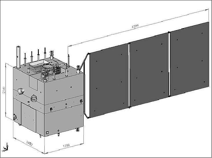
Bus dimensions | 1.8 m x 2.0 m x 2.2 m |
Solar panel size | 6.3 m x 2.6 m |
Propulsion system | Hydrazine for on-orbit maintenance, 16 x 1 N; 2 x 20 N |
S/C stabilization | 3-axis stabilization |
Nominal design life | 2 years |
Mission Status - CBERS-1
The spacecraft was operational for almost 4 years. On Aug. 13, 2003, CBERS-1 experienced an X-band malfunction in the downlink causing an end of all image data transmissions. On reflection, CBERS-1 surpassed its design life of two years by almost two years.
• The WFI instrument experienced a malfunction in May 2000, after seven months of service.
Sensor Complement
CBERS features a multisensor payload with imaging sensors of different spatial resolutions and collection frequencies. 12) 13) 14)
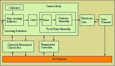
HRCC (High Resolution CCD Camera)
HRCC is the prime sensor on CBERS, developed and built by the Beijing Institute of Space Machines and Electricity and sponsored by CAST (Chinese Academy of Space Technology). The multispectral pushbroom instrument consists of the following main subsystems: optical, beam-splitting, detection, and an electronics unit; the auxiliary subsystems are: the side-looking reflector, relative calibration mechanism, focusing device, and a thermal control subsystem. Telescope focal length=520 mm (all refracting lens system); aperture=f/4; spatial resolution = 19.5 m (at nadir); IFOV=25 µrad; FOV= 8.4º; temporal resolution=26 days (nadir view), off-nadir view (pointable side-looking capability of ±32º, providing an increased observation frequency for a given region - any phenomenon or event detected by WFI may be zoomed by HRCC ) minimum time lag of 3 days; swath width = 113 km; objective: high resolution imaging. The pushbroom detector subsystem uses a Fairchild detector array (CCD-143A) with a pixel size of 13 µm x 13 µm. There are a total of five bands with 5812 pixels per band. Calibration: a tungsten filament lamp of known spatial profile provides illumination of the CCD arrays. Absolute calibration is made using a ground test site. 15)
Parameter | Band | Wavelength | Radiance (W/m2 sr) | SNR (dB) | ||
Maximum | Minimum | Maximum | Minimum | |||
MS band | B1 | 0.42-0.52 µm | 28.7 | 4.6 | 48 | 32 |
PAN band | B5 | 0.51-0.73 µm | 55.6 | 9.0 | 53 | 37 |
The HRCC instrument is steerable up to ±32º about nadir in the cross-track direction to obtain stereoscopic imagery.
Note: The HRCC instrument is also referred to as “HRCCD” in the literature.
Parameter | HRCC | IRMSS | WFI |
Spectral bands (µm) | 0.51 - 0.73 (PAN) | 0.50 - 1.10 (PAN) | 0.63 - 0.69 |
Spatial resolution | 20 m | 80 m (PAN & SWIR) | 260 m |
Swath width (FOV) | 113 km (8.32º) | 120 km (8.78º) | 890 km (60º) |
Temporal resolution | 26 days | 26 days | 3-5 days |
Cross-track pointing | ±32º |
|
|
Data rate | 2 x 53 Mbit/s | 6.13 Mbit/s | 1.1 Mbit/s |
Carrier frequency (X-band) | 8.103 and 8.321 GHz | 8.216 GHz | 8.203 GHz |
EIRP | 43 dBm | 39.2 dBm | 31.8 dBm |
Modulation | QPSK | BPSK | QPSK |
Tracking beam frequency | 8.196 GHz | 8.196 GHz | 8.196 GHz |
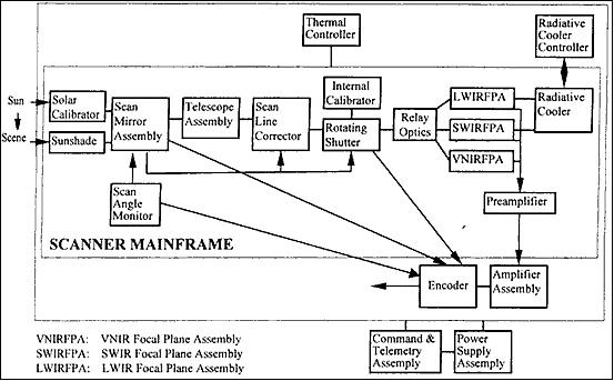
IRMSS (Infrared Multispectral Scanner)
IRMSS was developed and built by the Beijing Institute of Space Machines and Electricity and sponsored by CAST. 16) The instruments an optomechanical system (whiskbroom type), consisting of a main module [scan mirror, primary optics (Ritchey Chretien telescope), prime focal plane assembly, relay optics, detectors, etc.], an electronic unit, an onboard calibration assembly, a radiative cooler, and a thermal control unit. The telescope has an aperture diameter of 250 mm and a focal length of 1 m for the Pan and SWIR bands, and 0.5 m for the TIR (Thermal Infrared) band.
The telescope mirrors are made of fused silica and held by an invar structure. There are four spectral bands: 0.50-1.1 µm (panchromatic), 1.55-1.75 µm (SWIR), 2.08-2.35 µm (SWIR), 10.40-12.50 µm (TIR); spatial resolution: = 78 m for (0.5 - 2.35 µm ranges), 156 m for the TIR band; temporal resolution = 26 days; swath width = 120 km; IFOV=0.1 mrad (0.2 mrad for TIR band); FOV = 8.78º; objective: medium resolution imaging (complementary information to HRCC). The data rate of IRMSS is 6 Mbit/s.
The linear scan mirror performs cross-track scanning at a scan rate of 5.39 Hz and a scan angle of ±2.5º. Each of the four bands employs an eight-element staggered detector array in the along-track direction. For the TIR band, four of the eight detectors are spares. The Pan band detectors use silicon photodiodes, photovoltaic HgCdTe detectors are used for the SWIR bands, while the TIR band utilizes photoconductive HgCdTe detectors. The detector size is 0.1 mm x 0.1 mm for all bands.
The radiation from the prime focal mirror is divided into three parts by relay optics. IRMSS features three focal plane assemblies (Pan, SWIR and TIR). The Pan band is in the warm FPA while the SWIR and TIR bands are located in the cooled FPAs with temperatures of 148 K and 101 K, respectively. Active and passive thermal control methods are employed.
The onboard calibration system is used to correct the output changes of the scanner in flight. It includes an internal calibrator (lamp and blackbody) and a solar calibrator. The calibration precision is 3% for both, the band-to-band and the channel-to-channel calibration. The absolute calibration accuracy is <10%. Internal calibration occurs at every return stroke of the scan mirror, sun calibration is performed occasionally on ground command.
While IRMSS employs the same principles as the MSS and TM instruments on the Landsat series, it differs in many ways in the implementation approach such as in the three-level FPAs, the SWIR detectors, the relay optics, and the calibration system.
WFI (Wide-Field Imager)
WFI is of INPE design. WFI is also a complementary sensor to HRCC. It consists of an electro-optics module (optics, spectral filters, CCD detectors, and radiometric calibration device), a signal processor and a modulator. Spectral bands: 0.63-0.69 µm, 0.77-0.89 µm; spatial resolution = 260 m (3456 pixels per line); temporal resolution = 3-5 days; swath width = 890 km (FOV = 60º); data quantization = 8 bit; data rate = 1.1 Mbit/s; objective: acquisition of low-resolution wide-swath imaging (WFI provides a synoptic view).
Spectral bands (2) | 0.63-0.69 µm (red), 0.77-0.89 µm (NIR) |
FOV, IFOV (spatial resolution) | 1.04 radians (60º), 0.3314 mradians (260 m) |
Swath width | 890 km |
Band-to-band registration | <0.3 pixel |
Pixels per CCD line | 3456 (2 x 1728) |

DCS (Data Collection System)
In addition to the imaging payload, the satellite carries a DCS for environmental monitoring; a Space Environment Monitor (SEM).
The DCS is provided by INPE. Each DCP (Data Collection Platform) in the ground segment transmits randomly short digital data messages at a fixed rate (in UHF band). The DCS retransmits these messages in UHF and S bands to Earth. The DCS concept is similar to that of SCD-1.
DCS system access type | Random |
Uplink carrier frequency, EIRP | 401.635 MHz ±30 kHz (UHF), 33 dBm |
Downlink carrier frequencies | 2267.52 MHz (S-band); EIRP = 20 dBm |
EIRP (Effective Isotropic Radiated Power) | 20 dBm (S-band; 35 dBm (UHF-band) |
SEM (Space Environment Monitor)
Objective: detection of high-energy radiation. The CAST instrument consists of the following subsystems: PRD (Particle Radiation Detector), APD (Aurora Particle Detector), CRED (CMOS-IC Radiation Effect Detector), SDM (SEM Data Memory) and a 4.8 kHz subcarrier modulator.
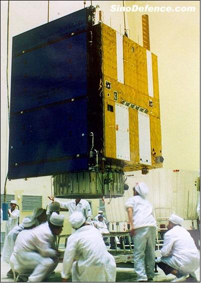
Spacecraft - CBERS-2A
The CBERS-2 spacecraft and its payload is identical to that of CBERS-1. The spacecraft was jointly developed by INPE and CAST. CBERS-2 was integrated and tested in the Integration and Test Laboratory of INPE. After conclusion and acceptance of the AIT (Assembly Integration and Test) activities in Brazil, the satellite was shipped the China, followed by some more environmental AIT tests. 17) 18) 19)
Launch
CBERS-2 (or ZY-1B) was launched successfully Oct. 21, 2003 from the Taiyuan Satellite Launch Center in China. The spacecraft carries the identical payload as CBERS-1. The intend is to provide continuity of observations.
Orbit: The orbital characteristics are identical to those of CBERS-1, i.e., sun-synchronous circular orbit; altitude = 778 km; inclination = 98.5º; nodal period = 100.26 minutes; mean local solar time on descending node at 10:30 AM; revisit period of 26 days.
Mission Status - CBERS-2
The spacecraft was retired in late 2007 when the imagery from CBERS-2B became available.
• HRCC operations were interrupted in May 2006 due to a power supply anomaly.
• The IRMSS instrument is inoperable since 2005.
Sensor Complement
The spacecraft carries the identical payload as flown on CBERS-1 (see description under CBERS-1).
• HRCC (High Resolution CCD Camera)
• IRMSS (Infrared Multispectral Scanner)
• WFI (Wide-Field Imager)
• In addition to the imaging payload, the satellite carries a Data Collection System (DCS) and Space Environment Monitor (SEM).
CBERS-2B (Zi Yuan-1 FM2B)
In 2005, the Sino-Brazilian consortium decided to built another satellite, called CBERS-2B, with essentially the same characteristics of CBERS-2 and -1. The objective of this intermediate satellite is to prevent a gap in the global coverage of CBERS imagery, since the launch of CBERS-3 is scheduled to arrive after the theoretical lifetime of CBERS-2B. 20)
Spacecraft - CBERS-2B
The new CBERS-2B spacecraft includes some upgrades for improved performance. In particular, a new GPS (Global Positioning System) receiver and a star tracker were added to the AOCS (Attitude Orbit Control Subsystem). The integration and testing of the satellite took place at INPE, São José dos Campos, Brazil. In April 2007, the spacecraft was shipped to the program partner organization in China, namely CAST (Chinese Academy of Space Technology) to prepare it for launch. The final integration tests on the CBERS-2B satellite were completed on September 12, 2007. 21)
The satellite is composed of two modules: a Cargo Module and a Service Module. The Cargo Module contains the optical systems (HRCC, HRPC and WFI) and the RSBCDA (Repetidor para o Sistema Brasileiro de Coleta de Dados Ambientais) - a Brazilian system for the collection of environmental data from the ground segment.
The Service Module contains the power sources, control systems, telecommunication systems and other elements necessary for the operation of the vehicle. Electrical power (1.1 kW at EOL) is provided by a deployable solar panel of size 6.4 m x 2.6 m (the solar panel is continuously articulated into the sun). The satellite is equipped with two Nickel Cadmium (NiCd) batteries (30 Ah each). A hydrazine thruster system is used to control attitude and for the orbital maintenance. The internal environment of the satellite is being kept by an active and passive thermal control system.
CBERS-2B has a total mass of 1450 kg, with bus dimensions of 1.78 m x 1.980 m x 2.14 m. The satellite has three axis stabilization. The design life is two years.
Launch
The launch of CBERS-2B took place on Sept. 19, 2007 on a Long March-4B vehicle (CZ-4B) from the Taiyuan Satellite Launch Center in China's Northern Shanxi province.
Orbit: Sun-synchronous orbit, altitude = 778 km, inclination = 98.5º; mean local solar time on descending node at 10:30 hours; period = 100.26 minutes, revisit period of 26 days.
RF communications: The onboard imagery is stored on two SSR (Solid-State Recorders). X-band downlink transmission of all image data in three channels, two channels are used for HRCC data (8103 and 8321 MHz) at data rates of 2 x 53 Mbit/s. The HW-DT channel is used to transmit the HRPC and the WFI playback data at a data rate of 60 Mbit/s. The S-band is used for TT&C services.
Mission Status - CBERS-2B
• The CBERS-2B mission was retired on May 10, 2010 due to an onboard power shortage/failure. 22)
- Since March 2010, Brazilian and Chinese technicians had been trying to restore nominal operations of CBERS-2B. In mid-April, the Brazilian and Chinese control centers failed in making contact with the CBERS-2B spacecraft: the satellite sent intermittent signals that indicated a lack of energy. As the chances of restoring nominal operations were minimal, CAST (Chinese Agency of Space Technology) and INPE decided to put an end to the CBERS-2B lifetime.
- Launched on September 19th, 2007, CBERS¿2B exceeded its designed life expectancy of two years. Approximately 270,000 satellite images were freely distributed to Brazilian users and more 60,000 to users from 40 different countries.
• In May 2009, Brazil and China agreed to supply data to African nations from their joint satellite program. Stations in Hartebeeshoek, South Africa; Aswan, Egypt; and Maspaloms, Spain, are to process and distribute data to African states from the CBERS-2B spacecraft. 23)
• On Sept. 19, 2008, CBERS-2B completed a full year in orbit.
• The CBERS-2B spacecraft was declared operational as of January 28, 2008, thus ending the commissioning phase of the spacecraft and its payload. The Brazilian Data Catalog is open to the public for HRCC and WFI data. 24) 25) 26)
• On Oct. 25, 2007, the cameras HRPC and WFI were turned on for the first time. 27)
• The first images are available on the web in Sept. 2007. 28)
Sensor Complement - CBERS-2B
The spacecraft carries the identical payload as flown on CBERS-1 and -2 (see description under CBERS-1). However, the IRMSS instrument - flown on the first two satellites of the CBERS series - was replaced by a high-resolution panchromatic camera, HRPC.
Parameter | HRCC | HRPC | WFI |
Spectral bands (µm) | 0.45 - 0.52 | 0.50 - 0.80 (PAN) | 0.63 - 0.69 |
Spatial resolution | 20 m | 2.7 m | 260 m |
Swath width (FOV) | 113 km (8.32º) | 27 km | 890 km (60º) |
Temporal resolution | 26 days |
| 3-5 days |
Cross-track pointing | ±32º |
|
|
Data rate (recorder playback) | 2 x 53 Mbit/s | 60 Mbit/s | |
Carrier frequency (X-band) | 8.103 and 8.321 GHz | 8.212 GHz | 8.212 GHz |
Modulation | QPSK | BPSK | QPSK |
HRCC (High Resolution CCD Camera)
This pushbroom instrument of China (developed and built by the Beijing Institute of Space Machines and Electricity) is pointable in the lateral (cross-track) direction which permits better event monitoring. The HRCC raw images in each band are composed by five parts (three arrays and two overlap regions) as presented in Figure 10. 29) 30)
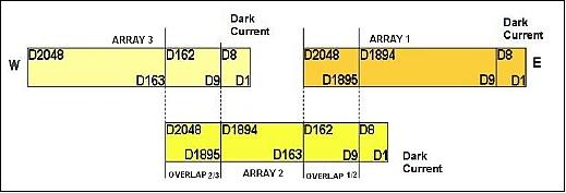
The detector array arrangement consists of three arrays, each of 2,048 pixels with two overlap regions of 154 pixels and a dark current region of 8 pixels in each array. These arrays are positioned inside the camera as a “divoli” configuration guaranteeing the complete and continuous cross-track imagery.
WFI (Wide-Field Imager)
The instrument is described under CBERS-1.
HRPC (High-resolution Panchromatic Camera)
HRPC is a new pushbroom camera of China on CBERS-2B replacing the IRMSS instrument. However, the imagery of HRPC is not available for distribution by international ground stations.
In addition to the imaging payload, the satellite carries a Data Collection System (DCS), referred to as RSBCDA, and Space Environment Monitor (SEM).
Ground Segment
CAST and INPE operate and maintain their own ground segment infrastructure, consisting of TT&C stations and a SCC (Satellite Control Center). The satellite operation and control, during the routine phase, including the orbital adjustment maneuvers to maintain the orbital phasing, are alternately accomplished by Brazil and China according to a unified program from the Xian Satellite Control Center.
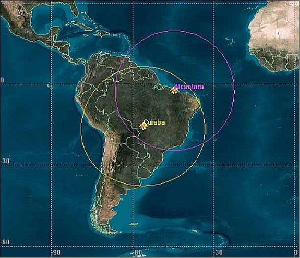
In Brazil, the SCC is located in São José dos Campos (at INPE), and by the ground stations are: Cuiabá and Alcântara. The received data are regularly transferred to the Image Processing Center of the Image Generating Division (DGI), in Cachoeira Paulista, for additional processing and dissemination to the user community.
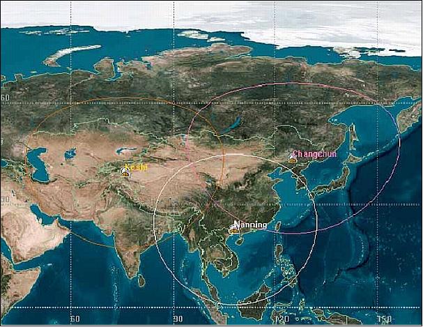
• China uses 3 ground stations to monitor and control the CBERS satellites (TT&C function): Changchun, Nanning, and Keshi. The receiving stations of the CBERS imagery are located in: Beijing, Nanning, and Wulumuqi.
• Brazil uses 2 ground stations to monitor and control the CBERS satellites (TT&C function): Cuiabá and Alcântara. The receiving stations of the CBERS imagery are located in: Cuiabá and Boa Vista (planned).
Operation and Data Policy
The operation of CBERS satellites is shared between Brazil and China according to a handover schedule. All special requests and agreements for direct reception in third countries are managed and negotiated by both sides. The data distribution policy adopted for CBERS Program has followed a pattern of enlarging the distribution while lessening the costs. In Brazil and China, the full resolution data are delivered free through the internet. Third parties interested in receiving direct downlink CBERS data are encouraged to assume the same free data policy (Ref. #.
The application of this data policy in Brazil and in China resulted in an enormous increment of new users and new applications. In Brazil, for example, INPE delivers regularly more than 300 scenes a week since the application of this data policy. Up to now, more than 350,000 CBERS-2 scenes have been delivered around the country. Seeking to improve the remote sensing in South America, and as part of this free distribution policy, Brazil has adopted the same policy for its neighboring countries. Because of this Brazilian policy, South America countries are regularly using CBERS-2 data for their remote sensing development and surveying policies.
• In March 2006, the USGS (United States Geological Survey) downlinked the first CBERS-2 data at the EDC (EROS Data Center) in support of the Landsat Data Gap Study.31)
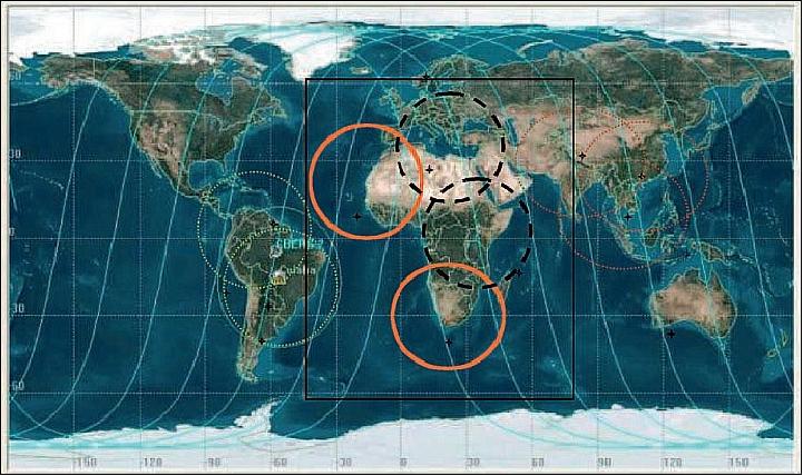
• At the Third Ministerial Summit on Earth Observation and the Fourth Plenary meeting of the Group of Earth Observation (GEO) in Cape Town, South Africa (Nov. 30, 2007), China and Brazil granted free downlink licences and upgrades of the ground stations, which receive, process, store and distribute the imagery free of charge to all interested African countries inside the footprints of their receiving antennas. The locations of the ground stations are (Figure 13): Canary Islands (Spain), Hartebeesthoek (South Africa), Malindi (Kenya), and Matera (Italy). 32)
Brazil and China agreed that the CBERS program, a major model of successful “south-south cooperation” in space technology for global land cover remote sensing, will keep a data policy based on public good and data continuity until 2015 (as long as the satellite family will remain operational). - The imagery of the four ground stations is being distributed through the GEONetCast system, set up by GEO.
Background: Already in the summer of 2004, Brazil and China (INPE, CRESDA) changed the data policy for the CBERS Program including provisions for reception, processing and dissemination of CBERS imagery to countries other than Brazil and China. Note: CRESDA (China Center for Resource Satellite Data and Applications), Beijing, was established in 1991.
The downlink data is made open to any country or organization, based on the conception that CBERS imagery will be distributed by licensed representatives who operate an application system infrastructure (ground station) that performs data reception and processing. Each licenced ground station receives the image raw data and process it into image products, which will then be distributed to users. The licensing of CBERS data downlinks is based on fees which are charged on a time basis of data reception. 33)
References
1) Zhu Yilin, “Ziyuan-1, China's First Earth Resources Satellite (CBERS),” Earth Space Science Review, July-September 1994, Vol. 3, No. 3, pp. 16-19
2) “The China-Brazil Earth Resources Satellite Program,” paper provided by G. Santana of INPE
3) “CBERS Spacecraft: Conception and Design,” paper presented by E. A. Parada Tude of INPE and by C. Quinnan of CAST at the 1st Brazilian Symposium of Aerospace Technology, Sao Jose dos Campos, Aug. 27-31, 1990
4) G. K. Rayalu, et al., “Multispectral and Multitemporal Optical Sensors of CBERS,” INPE internal paper
5) C. de Oliveira Lino, M. G. Rodrigues Lima, G. L. Hubscher, “CBERS - An International Space Cooperation Program,” Acta Astronautica, Vol. 47, No 2-9, 2000, pp. 559-564
6) José Carlos Epiphanio, Gilberto Câmara, “CBERS Program: An Overview,” April 2005, URL: http://www.dpi.inpe.br/gilberto/present/cbers_overview.ppt
7) “Zi Yuan CBERS (China-Brazil Earth Resources Satellite),” URL: http://www.globalsecurity.org/space/world/china/zy-1.htm
8) Xingchao Li, “Chinese Optical instruments: CBERS, HJ-1 and Beijing-1,” Oct. 13-18, 2008, Wuhan University, China, URL: http://dragon2.esa.int/landtraining2008/pdf/D1L3b_Optical_Li.pdf
9) “Brazil, China To Postpone Joint Satellite Launching To 2011,” Space Travel, Feb. 16, 2010, URL: http://www.space-travel.com/reports/Brazil_China_To_Postpone_Joint_Satellite_Launching_To_2011_999.html
10) https://web.archive.org/web/20040228224751/http://www.cbers.inpe.br/en/programas/cbers1-2_caract.htm
11) Ye Yun Shang , Li Quan Ming , “ A new type of X-band data transmission antenna used on CBERS-1 satellite,” Proceedings of the 6th International Symposium on Antennas, Propagation and EM Theory, Oct. 28 to Nov. 1, 2003, Beijing, China
12) https://web.archive.org/web/20040228223647/http://www.cbers.inpe.br/en/programas/cbers1-2_cameras.htm
13) Huaiyi Wang, Shitao Wang, Wenpo Ma, Tao He, “Development and operation of the IRMSS and CCD camera for CBERS,” Proceedings of SPIE, Vol. 4130, Infrared Technology and Applications XXVI, Bjorn F. Andresen, Gabor F. Fulop, Marija Strojnik, Editors, Dec. 2000, pp. 9-12
14) Xingchao Li, “Chinese Thermal instruments: CBERS and HJ-1B,” Wuhan University, China, Oct. 13-18, 2008, URL: http://dragon2.esa.int/landtraining2008/pdf/D1L4b_Thermal_Li.pdf
15) D. Lin, S. Cui, “CCD Camera for CBERS,” Proceedings of the Asian Conference on Remote Sensing (ACRS), Hongkong, Nov. 1999, pp. 285-288,
16) W. Huaiyi, M. Wenpo, “The IRMSS for CBERS,” Proceedings of the Asian Conference on Remote Sensing, Hongkong,Nov. 1999, pp. 902-905
17) G. Chander, “Overview of the CBERS-2,” Minutes from USGS-INPE meeting, São José dos Campos, April 22, 2005, URL: http://calval.cr.usgs.gov/documents/Landsat_Data_Gap_Studies/CBERS2.pdf
18) Antonio Machado e Silva, Frederico Liporace,Marcelo Santos, “CBERS: a Reference in the Brazilian Space Program,” JACIE 2007 (Joint Agency Commercial Imagery Evaluation) Workshop, March 20-22, 2007, Fairfax, VA, USA, URL: http://calval.cr.usgs.gov/JACIE_files/JACIE07/Files/112Siilva.pdf
19) Gyanesh Chander, “An Overview of the CBERS-2 Satellite and comparison of the CBERS-2 CCD data with the L5 TM data,” Proceedings of JACIE 2006 Workshop, March 14-16, 2006, Fairfax, VA, USA, URL: http://calval.cr.usgs.gov/JACIE_files/JACIE06/Files/37Chande.pdf
20) Space Technology Activities at INPE,” UK-Brazil Workshop on Space Science Technology, Oct. 29 - Nov. 1, 2007, São José dos Campos, SP, Brazil, URL: http://www.anodaciencia.com.br/multimidia/multimidia_20071218140449.pdf
21) https://web.archive.org/web/20040812053453/http://www.cbers.inpe.br/en/programas/cbers1-2.htm
22) Julio Dalge, Hilcea Ferreira, “China-Brazil Earth Resource Satellite announces the end of CBERS-2B operations - May 12, 2010,” GEO Work Plan Symposium, Pretoria, South Africa, May 17-19, 2010, URL: ftp://ftp.earthobservations.org/201005_Work_Plan_Symposium/Presentations/CB-09-05b_2010_GEO_WPS.pdf
23) “Brazil, China agree to supply satellite data to Africa,” May 20, 2009, URL: http://www.topnews.in/brazil-china-agree-supply-satellite-data-africa-2168868
24) “China To Monitor Global Disasters Through Satellite,” Terradaily, Jan. 29, 2008, URL: http://www.terradaily.com/reports/China_To_Monitor_Global_Disasters_Through_Satellite_999.html
25) Antonio Machado, “Status of CBERS-2B - Data Reception, archiving processing, and distribution,” JACIE 2008, FairFax, VA, USA, March 25-27, 2008, URL: http://calval.cr.usgs.gov/JACIE_files/JACIE08/2008_JACIE_DVD/Thursday_AM/Machado_Cbers.pdf
26) Julio Dalge, “CBERS-2B – Radiometric and Geometric Quality Assessment,” JACIE 2008, FairFax, VA, USA, March 25-27, 2008, URL: http://calval.cr.usgs.gov/JACIE_files/JACIE08/2008_JACIE_DVD/Thursday_AM/Dalge_CBERS2B.pdf
27) http://www.cbers.inpe.br/?hl=en
28) http://www.cbers.inpe.br/?content=galeria_imagens_2b&hl=en
29) Flávio Jorge Ponzoni, Bráulio Fonseca Carneiro Albuquerque, “Pre-Launch Absolute Calibration of CCD/CBERS-2B Sensor,” Sensors 2008, Vol. 8, 6557-6565; Oct. 25, 2008, DOI: 10.3390/s8106557
30) Flávio J. Ponzoni, Jurandir Zullo Junior, Rubens A. C. Lamparelli, “In-flight absolute calibration of the CBERS-2 CCD sensor data,” Anais da Academia Brasileira de Ciências (2008) 80(2): 373-380, (Annals of the Brazilian Academy of Sciences), ISSN 0001-3765, URL: http://www.scielo.br/pdf/aabc/v80n2/a15v80n2.pdf
31) Greg Stensaas, Gyanesh Chander, “Landsat Data Gap Studies: Potential Data Gap Sources,” Jan. 10, 2007, URL: http://landsat.usgs.gov/documents/science_Landsat_Data_Gap_Stensaas_Chander.pdf
32) Joao Vinei Soares, Jose Carlos Epihanio, Gilberto Camara, “CBERS-2B for Africa,” Annex of Early Achievements to the Report on Progress 2007, Cape Town Ministerial Summit,” URL: http://www.earthobservations.org/.../2007_Annex_of_Early_Achievements_to_the_Report_on_Progress.pdf
33) Gilberto Câmara, Guo Jian Ning, “CBERS Data Policy,” June 2004, URL: http://mtc-m16c.sid.inpe.br/col/dpi.inpe.br/banon/2006/08.03.19.25/doc/appl_07_2004.pdf
The information compiled and edited in this article was provided by Herbert J. Kramer from his documentation of: ”Observation of the Earth and Its Environment: Survey of Missions and Sensors” (Springer Verlag) as well as many other sources after the publication of the 4th edition in 2002. - Comments and corrections to this article are always welcome for further updates (eoportal@symbios.space).