CHAMP (Challenging Minisatellite Payload)
EO
Atmosphere
Atmospheric Temperature Fields
Mission complete
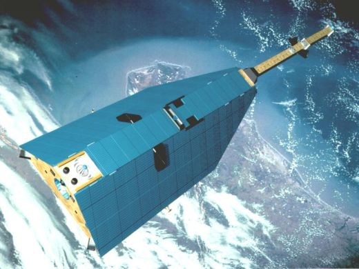
Launched in July 2000, Challenging Minisatellite Payload (CHAMP) was operated by the German Aerospace Centre (DLR). It acquired spatial and temporal measurements of Earth’s gravitational, magnetic, and electric fields which assisted in a variety of fields such as climate studies, geodesy, and geophysics.
Quick facts
Overview
| Mission type | EO |
| Agency | DLR |
| Mission status | Mission complete |
| Launch date | 15 Jul 2000 |
| End of life date | 19 Sep 2010 |
| Measurement domain | Atmosphere, Gravity and Magnetic Fields |
| Measurement category | Atmospheric Temperature Fields, Gravity, Magnetic and Geodynamic measurements, Atmospheric Humidity Fields |
| Measurement detailed | Magnetic field (scalar), Magnetic field (vector), Atmospheric specific humidity (column/profile), Atmospheric temperature (column/profile), Geoid, Gravity field |
| Instruments | CHAMP Gravity Package (Accelerometer+GPS), CHAMP GPS Sounder, CHAMP Magnetometry Package (1 Scalar + 2 Vector Magnetometer) |
| Instrument type | Magnetic field, Atmospheric temperature and humidity sounders, Gravity instruments |
| CEOS EO Handbook | See CHAMP (Challenging Minisatellite Payload) summary |
Summary
Mission Capabilities
CHAMP had seven different instruments onboard.
The GPS TRSR-2 (TurboRogue Space Receiver) and the Laser Retro-Reflector (LRR) pinpointed the satellite's position in space. The Space Three-axis Accelerometer for Research (STAR) measured all non-gravitational accelerations (drag, solar and Earth radiation pressure) of the satellite so the experienced gravity could be accurately determined. The Magnetometer Instrument Assembly System (MIAS) comprised of one Overhauser scalar Magnetometer (OVM) and two Fluxgate vector Magnetometers (FGM) that measured the magnetic field strength and direction, as well as an Advanced Stellar Compass (ASC) that provided an attitude reference for the magnetometers. The Digital Ion Drift Meter (DIDM) measured the ion drift in the ionosphere to calculate the strength and direction of Earth’s electric field.
Performance Specifications
GPS TRSR-2 had a spatial accuracy of 30 m and the LRR had an accuracy of 0.02 m. STAR had an accuracy of 1.5 x 10⁻⁹ ms-2. The OVM had an accuracy of 0.5 nT, the FGMs had a resolution of 2 nT, and the ASC had an accuracy of 4 arcseconds. DIDM measured ion drift with a resolution of 1° in direction and 130 m/s in speed.
CHAMP undertook a sun-synchronous orbit with an altitude of 454 km, an inclination of 87.3°, and a period of 93.55 minutes.
Space and Hardware Components
The 522 kg CHAMP satellite was launched aboard a Kosmos-3M launch vehicle manufactured by PO Poljot, from the Plesetsk Cosmodrome in Russia.
Telemetry, Tracking, and Command (TT&C) were performed via S-band radio frequencies with an uplink rate of 4 kbit/s and a downlink rate of 32 kbit/s or 1 Mbit/s.
CHAMP (Challenging Minisatellite Payload)
CHAMP is a German BMBF-funded geophysical minisatellite mission of GFZ (GeoForschungsZentrum), Potsdam, Germany, in cooperation with DLR (German Aerospace Center). The satellite was built by the German space industry with the intent to foster high-tech capabilities, especially in the East German space industry. The spacecraft's prime contractor is DJO (Jena Optronic GmbH) in Jena, a daughter of DASA (now EADS Astrium GmbH).
Note: A renaming of GFZ took place on June 17, 2008. The new name is: Helmholtz-Zentrum Potsdam GFZ German Research Center for Geosciences. 1)
The overall science objectives are in the following fields of investigation:
• Global long-to-medium-wavelength recovery of the static and time-variable Earth gravity field from orbit perturbation analyses for use in geophysics (solid Earth), geodesy (reference surface), and oceanography (ocean currents and climate), supported by a feasibility test of GPS altimetry for ocean and ice surface monitoring
• Global Earth magnetic field recovery (solid Earth and solar-terrestrial physics)
• Atmosphere/ionosphere sounding by GPS radio occultation with applications in weather forecasting, navigation, space weather, and global climate change.
Spacecraft
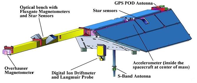
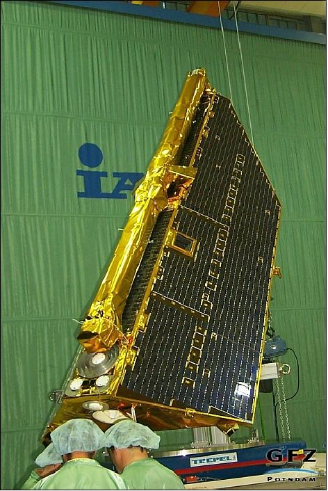
The structure of the satellite (FLEXBUS of EADS Astrium GmbH) features a trapezoidal body with overall dimensions of 4.3 m length x 0.75 m height x 1.6 m/0.4 m width at base/top. A boom of 4 m in length accommodates the magnetometry assembly (the boom is nominally pointed into the flight direction).
The S/C is three-axis stabilized (Earth pointing) with three magnetorquers and cold gas propulsion for attitude and orbit change manoeuvres; attitude control is < 2º, and attitude knowledge is provided by two-star sensors on the boom and on the body, respectively, each one with two sensor heads (0.01º orientation accuracy), the star sensor instrument is referred to as ASC (Advanced Stellar Compass) and is manufactured by DTU, Denmark [dual-head CCD (hot), Quad A/D (2 cold) and single DPU].
S/C design life = five years; total S/C mass = 522 kg (including 30 kg of propellant); payload mass = 32 kg; S/C power = 150 W (50 W for payload) provided by a solar array of 6.9 m2 in size; in addition there are 10 cells of NiH2 batteries (16 Ah) for night phase operations. Passive thermal control is provided by paints and multi-layer insulation. 2)
The ESA standard OBDH (Onboard Data Handling) data bus provides support for all data handling functions. The AOCS (Attitude and Orbit Control Subsystem) is fully integrated into OBDH. In addition, OBDH has limited autonomous capability of FDIR (Failure Detection, Isolation and Recovery) events which might occur during data handling.
CESS (Coarse Earth-Sun Sensor). An Astrium-developed patented attitude package consisting of six single sensor heads arranged on the S/C in such a way that an omnidirectional and unobstructed view of space is given. Each head features two equally sized optical surfaces of different properties in the spectral ranges (the IR absorptance is the same but the VIS absorptance is different). Thermistors serve as detectors. The hardware configuration permits us to take temperature measurements driven by the Earth and sun illumination. The measurements are weighted, averaged, and extrapolated to steady-state equilibrium temperatures. An algorithm derives overall heat flux based on the input temperatures and corrects for albedo. The output is a computed Earth vector and a computed sun vector in the S/C coordinate system. CESS pointing performance is within 6º for sun vector knowledge and within 15º for Earth vector knowledge. On CHAMP, CESS serves as a low-cost and low-mass demonstration package. The intent of the CESS design is to permit future S/C to fall back on a safe attitude control in case of a failure or degraded service of components of the regular attitude control system. CESS offers also its services for initial acquisition and coarse pointing in general. 3) 4)
RF communications: Onboard storage capacity of 1 Gbit. All data links are in S-band using BPSK modulation. Spacecraft science data are received by the DLR/DFD station in Neustrelitz (downlink frequency of 2.280 GHz at a data rate of 1 Mbit/s). S/C operations are provided at DLR/GSOC in Oberpfaffenhofen via the Weilheim station (TT&C data in S-band; uplink at 2.093 GHz and 4 kbit/s; downlink at 2.28 GHz and 32 kbit/s). 5), 6) 7)
In addition, GFZ installed two automatic payload data acquisition stations on Svalbard (Ny Alesund), one for CHAMP and one for GRACE, to speed up the data processing and distribution chain for the various weather services. The polar location of Svalbard makes it possible to have access to the data on almost all orbits.
Launch
A spacecraft launch took place on July 15, 2000, from Plesetsk on a Russian Kosmos-3M launcher - along with two secondary payloads: the MITA satellite of ASI, Italy and a Rubin nanosatellite of OHB, Bremen.
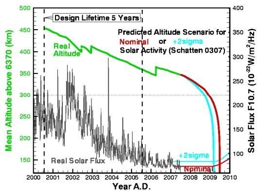
Initial orbit: perigee = 418 km, apogee = 474 km (the orbit is decaying to about 300 km at end of the design life of five years), inclination = 87.275º. Period of about 94 minutes. The orbit is near polar but non-sun-synchronous.
Mission Status
End of the CHAMP mission: After more than 10 years in orbit and 3718 days of providing information to researchers on the ground, the satellite burnt up on September 19, 2010, over the sea of Okhotsk, somewhere between eastern Siberia, the Russian peninsula of Kamchatka, and Japan. 8)
• The CHAMP mission is operating nominally in the spring of 2010 (in its 10th-year on-orbit, the nominal design life is 5 years). 9)
• In February 2010, the orbital altitude of CHAMP is 296 km. On Feb. 22, 2010, the spacecraft was rotated by 180º about the nadir axis, resulting in a boom orientation which is opposite to the velocity vector. This attitude is considered to be more stable in view of an increasingly denser atmospheric environment during the approaching orbital decay phase.
• The mission end is expected to occur in Q4 of 2010 due to the fairly low altitude of the spacecraft (Ref. 9).
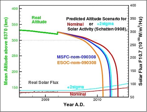
• At the end of March 2009, a fourth orbit-raising manoeuvre of the mission is planned. After this event, the operational phase of the mission is expected to end in the spring of 2010 (due to the natural orbital decay).
• In October 2008, a change to the redundant GPS receiver took place; this in turn required a switch-off of the occultation measurements since the onboard occultation software wasn't up to par for this event.
• Three orbit-raising manoeuvres were undertaken so far: in June 2002, in December 2002, and in March 2006. In the mission phase 2006, a natural mission end was expected in the timeframe of 2009-2010. Further operational funding was granted until the end of the mission. 10) 11)
• Since April 2001, another receiving station was added at Ny-Alesund, Spitzbergen. The station offers a downlink on virtually every orbit thus providing inputs for the generation of atmospheric quicklook data products. In the meantime, the station received a redundant configuration for continuous operational availability.
Sensor Complement
BlackJack (GPS Flight Receiver)
BlackJack is a new generation instrument of TRSR (TurboRogue Space Receiver) and of GPS/MET heritage, first flown on SRTM. BlackJack is being provided and built by NASA/JPL. The instrument is also referred to as TRSR-2. The objectives are to perform the following functions: 12) 13)
• BlackJack is a dual-frequency GPS receiver system for precise (cm accuracy range) orbit determination and continuous coverage
• The instrument observes in parallel ionospheric electron content and provides atmospheric soundings permitting the derivation of atmospheric vertical profiles of density, pressure, temperature (of water vapour) and ionospheric electron density profiles (refractive occultation monitoring)
• Experimental use of the GPS signals reflected from the ocean's surface for altimetric measurements.
The LEO CHAMP S/C and the MEO GPS satellite constellation establish a so-called high-low satellite-to-satellite (SST) link for the BlackJack instrument.
BlackJack features a new DSP (Data Signal Processor) ASIC, a 16-channel GPS instrument capable of tracking up to 12 GPS signals at once for POD (Precise Orbit Determination); there are four ASICs in each receiver so the instrument can track up to 48 signals in parallel, in any mode (C/A, P, or codeless). Two new ASIC capabilities (among several) are:
• A patented new enhanced “quasi-codeless” tracking of L2, providing a measurement error comparable to that achieved by the TRSR instrument with P-code tracking
• Special software for atmospheric occultation and ocean reflection applications. This particular BlackJack implementation is the first 4-antenna version.
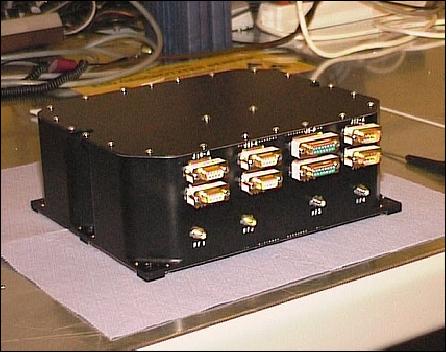
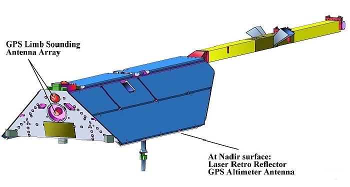
The BlackJack receiver system consists of the RPA (Receiver/Processor Assembly) containing the RF down-converter sections, an internal bus and the cold-redundant baseband processor cards, the RF coaxial cables to the 4 antennas and the antennas themselves. The RPA antennas are pointed: in the zenith direction, two in the aft direction, and in the nadir direction. The zenith-pointing antenna is used for the simultaneous tracking of up to twelve GPS satellites to derive CHAMP's trajectory. The receiver performs phase measurements of both GPS frequencies L1 and L2, and code pseudoranges. The GPS output is the complete navigation solution, i.e., position, velocity and time for use in on-board orbit prediction and attitude control, in addition to the direct phase and pseudorange measurements from GPS-LEO satellite-to-satellite tracking which is used for precise offline orbit restitution.
The receiver has the following measurement modes: 14) 15)
• Tracking mode (default), 0.1 Hz
• Occultation mode: in this mode the receiver software schedules every 50 Hz tracking of setting occultations of up to four GPS satellites
• Altimetry mode: in this mode, the nadir antenna collects specular reflections of GPS signals from the surface of the oceans.
The BlackJack aft antennas are used for limb sounding. High-resolution atmospheric soundings can be retrieved when the radio path between the LEO GPS receiver and one GPS satellite traverses the Earth's atmosphere. This occultation technique employs dual-frequency carrier-phase observations of retarded signals (atmospheric path delays) which permit the derivation of atmospheric profiles of density, pressure, and temperature (or water vapour) in an altitude range from 85 km to the ground. All observables are sampled 50 times per second. In parallel to limb sounding a non-occulted GPS satellite is tracked, which allows the correction of system inherent biases. Ionospheric occultation is performed with 1 Hz samples.
A nadir-pointing antenna is used experimentally to receive specular reflections of the GPS signals from the ocean's surface. In this case, the receiver does not track the direct GPS signals but instead performs an “open-loop” sampling of the GPS spectrum for later analysis on the ground. Therefore, any and all reflected GPS signals that happen to be present in the sampled spectrum are being captured, though that may not generally be more than one or two. The sample rate for this operations mode is about 100 samples/s or about the same as in occultation mode. Knowing both the position of CHAMP and the transmitting GPS satellite, it is possible to derive the precise position of the S/C with respect to the ocean's surface and thus to gain information about its topology.
The BlackJack data rate is between 0.4 - 17 kbit/s, depending on occultation events (0, 1, or 2 occultations); the mean data rate is 2.5 kbit/s, which amounts to about 27 MByte/day.
BlackJack (TRSR-2) is completely self-initializing from a cold start. Once started, it operates fully autonomously. The receiver decides which GPS S/C to track in the various tracking modes, solves for the state vector (navigation solution) for the CHAMP satellite, schedules occultation and altimetry measurements and solves for the offset between the GPS receiver time and the GPS time in order to provide an extremely accurate synchronization pulse for the CHAMP onboard subsystem.
The BlackJack autonomous orbit determination software contains JPL's RTG (Real-Time GIPSY) package. The RTG orbit determination module is a compact and portable software package optimized for real-time processing and is designed for use on embedded systems. RTG makes use of an extended Kalman filter as well as precise dynamic models for orbiting receivers. RTG simulations using actual GPS data from the CHAMP spacecraft together with JPL's GDGPS (Global Differential GPS) corrections demonstrate 30 cm 3-D rms real-time orbit determination capabilities. 16)
Computed position in telemetry (navigation solution) | < 60 m |
Time calibration accuracy | < 1 μs from GPS time (resolution 0.1 ns) |
Dual-frequency range and integrated carrier for POD (Precise Orbit Determination) at a 1s interval: | |
Phase (ionosphere-free) | < 0.2 cm |
Dual-frequency integrated carrier phase and amplitude for atmospheric occultation: | |
Phase (ionosphere-free) | < 0.05 cm |
Limb-sounding observables (prior to atmospheric de-focusing): | |
L1 carrier phase | < 0.05 cm (1 s) |
The measurement accuracy of the GPS receivers and the orbital altitude of CHAMP between 300 to 500 km enables a spatial resolution of the gravity field of approximately 500 km. The expected accuracy of the corresponding spectral range is by a factor of ten higher than realized in the present gravity field models. That means that the geoid can be determined with an accuracy of one centimetre for wavelengths down to 1000 km.
STAR (Space Three-axis Accelerometer for Research Mission)
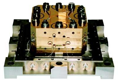
STAR is an accelerometer system provided by CNES and developed by ONERA (Office National d'Etudes et de Recherches Aerospatials), France. The objective is to measure all non-gravitational accelerations of the satellite (drag, solar and Earth radiation pressure) in order to determine the Earth's gravity field from purely gravitational orbit perturbations (orbit from BlackJack). The accelerometer measurement principle is based on the electrostatic suspension of a proof mass in a cage. The instantaneous position of the proof mass is measured by three capacitive sensors which permit a determination of the acceleration vector. The instrument has a dynamic range of ±10-4 ms-2, a resolution of better than ±3 x 10⁻⁹ ms-2, and a frequency range of 10-1 to 10-4 Hz. The STAR instrument is positioned at the centre of gravity of CHAMP to minimize the influence of measurement disturbances due to rotational accelerations and gravity gradients. STAR is also connected to a star sensor (ASC of DTU, Denmark) with two heads to provide the accelerometer's axes orientation. The accelerometer proof-mass is positioned at the centre of gravity of CHAMP. 17) 18)
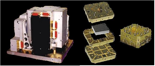
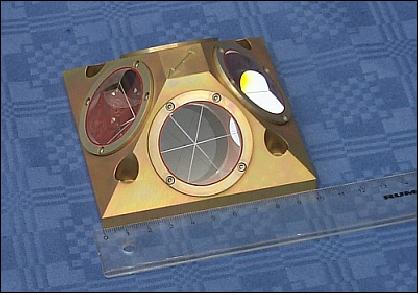
LRR (Laser Retro Reflector)
LRR is developed at GFZ. A passive optical device for accurate satellite tracking from ground laser ranging stations of the SLR network. LRR consists of four cube corner prisms to reflect short laser pulses back to the transmitting SLR ground station. Laser pulses from the ground typically have durations of 35 - 100 picoseconds, providing a single-shot range accuracy of 1 to 2 cm without any ambiguities.
LRR data are used for:
a) precise orbit determination in connection with BlackJack for gravity field recovery,
b) calibration of the onboard BlackJack system,
c) technological experiments such as two-colour ranging to achieve millimetre ranging accuracies.
MIAS (Magnetometer Instrument Assembly System)
MIAS is a boom-mounted package consisting of an Overhauser scalar magnetometer (OVM, built by LETI of Grenoble, France), two fluxgate vector magnetometers (FGM), and two-star imagers to provide attitude information for FGM (FGM and the two-star sensors are built by DTU, Denmark).
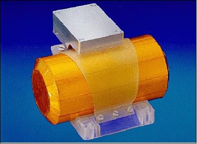
The measurement method of OVM is based on proton Larmor precession in a weak magnetic field (the Larmor frequency's being directly proportional to the magnetic field permits the derivation of the absolute total Earth magnetic field intensity). The absolute intensity is used for calibrating the FGM observations. OVM measurement range = 16,000 - 64,000 nT, resolution = 0.1 nT, absolute accuracy = 0.5 nT, sampling rate = 1 Hz.
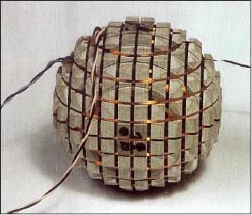
The measurement principle of FGM is based on `vector feedback geometry' (three sets of coaxial coils are mounted equidistant on the surface of a 9 cm diameter sphere, with the three sets orthogonal to each other - the coil currents are a measure of the three magnetic field components). Two FGMs are located on the boom, 60 cm apart, permitting simultaneous measurement of both FGMs in a `gradiometer' arrangement. The FGMs have a measurement range of ±64,000 nT and a resolution of 1 to 2 nT. The sampling rates are at 32 Hz (both sensors active) or 64 Hz (one sensor active), corresponding to spatial resolutions of about 200 or 100 m, respectively. - The FGMs are rigidly mounted on an optical bench also housing two-star sensors.
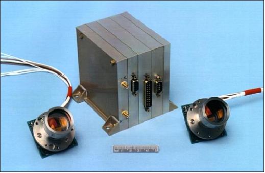
ASC (Advanced Stellar Compass):
ASC was designed and built by DTU (Technical University of Denmark in Lyngby). The objective is to provide an attitude reference instrument with a precision of a few arcseconds aboard the satellite (to measure the magnetic field with a vector precision of a fraction of a nT). The design of this star imager is based on a new development presently flown on the Ørsted satellite. On CHAMP, there are two ASC systems, each consisting of two Camera Head Units (CHU) and a common Data Processing Unit (DPU). One ASC is part of the magnetometry optical bench unit on the boom, the other provides high-precision attitude information for the instruments fixed to the S/C body. Additionally, the ASCs serve as sensors for the satellite attitude control system. The ASC is a fully autonomous system that directly outputs the attitude quaternions in a preselectable coordinate system. 19) 20)
ASC measurement principle: An image of the stars within the FOV is acquired by integrating the light focused onto a photosensitive CCD array. The pattern is serially read out, digitized and fed to a microprocessor. The digital image is than sifted for stars brighter than mV = 6 and corrected for lens distortions resulting in a list of calculated star centroids with sub-pixel precision. The determined star centroids are subsequently matched against real star positions derived from an onboard HIPPARCOS star catalog. The star attitude which fits best the observed pattern is the output result. For further improvement of the attitude solution a GPS updated orbit model is maintained to correct for astronomical aberration and also the epoch of star constellation is taken into account.
The ASC on the boom provides the high attitude precision needed for the magnetic field vector measurements. The ASC on the spacecraft body provides attitude data primarily for the STAR and DIDM instruments. This information is also required for the proper reduction of the GPS data, laser ranging data and for attitude control.
Attitude determination precision | 4 arcsec (3 sigma, BOL) |
FOV (Field of View) | 18.4º x 13.4º |
Sampling rates | 1 Hz (nominal), 0.5 Hz, 2 Hz |
Magnetometer moment CHU | 10-5 A/m2 |
Power | 8 W |
Mass: CHU, DPU | 0.20 kg (excluding baffles), 0.80 kg |
Dimensions: CHU, DPU | 50 mm x 50 mm x 45 mm, 100 mm x 100 mm x 100 mm |
DIDM (Digital Ion Drift Meter)
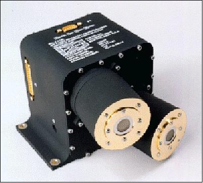
The instrument is provided by AFRL (Air Force Research Laboratory), Hanscom Air Force Base, Bedford, MA (USA), and built by Amptek Inc. of Bedford. DIDM is an enhanced version of the first DIDM instrument, flown on STP-4 (Space Test Program-4) with a launch in Oct. 1997. DIDM on CHAMP includes a charge collecting plate to account for spacecraft charging. The objective of DIDM is to measure the Earth's electric field parallel to the magnetic field (in-situ measurements of the ion distribution and its moments within the ionosphere). DIDM measures magnitude and direction of the incoming ion flux. The electric field is derived from the relationship between electric field, measured ion drift velocity and measured magnetic field strength. 21) 22)
Note: SSI/ES (Special Sensor Ionospheric Plasma Drift/Scintillation) instruments have been flown on DMSP (Defense Meteorological Satellite Program) series satellites of DoD (Department of Defense) for a long period of time (20 years) to monitor the space plasma. These instruments rely on analog technology and older electronics. As a result they have limited dynamic range, are physically large and heavy, and have significant power requirements. The follow-on US meteorological satellite program (NPOESS), which will replace DMSP in the first decade of the 21st century, requires higher resolution, sensitivity, accuracy, and dynamic range for its plasma measurement devices. The goal is for a next generation DIDM instrument to be the standard drift meter aboard the NPOESS spacecraft series.
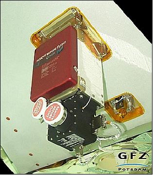
DIDM utilizes miniaturized state-of-the-art detector components and on-board digital signal processing. The instrument consists of two side-by-side ion detectors [MCP (Microchannel Plate)type] arranged within one unit of 2.2 kg mass. Both apertures are facing the S/C ram direction. Both detectors can measure the normal and perpendicular velocity components of incident ions. Ions entering through a pinhole aperture fall into a Retarding Potential Analyzer (RPA) cup. Those ions with energies higher than a certain threshold potential are electrostatically focused onto charge multiplying microchannel plates (MCPs) and high-resolution wedge and strip charge detecting anodes. The images created by these impacting ions on the anode are digitally processed on-board to reconstruct the full 3-D ion velocity vector.
A PLP (Planar Langmuir Probe) is operated in combination with DIDM. This device provides auxiliary data needed to interpret the ion drift measurements. Quantities that can be derived from the PLP sweeps are S/C potential, electron temperature, and density. The PLP voltage is swept for 1 s every 15 seconds typically between ±2.5 V in 32 steps. A selectable bias voltage can be added to account for the S/C potential. By interpreting the measured current/voltage characteristic the plasma parameters are being determined. The S/C floating potential is measured during the remaining 14 seconds of the measuring cycle.
Direct measurements | Ion density: 102 - 106 ions/cm3 |
Indirect measurements | Ion drift velocity: 0 - 6 km/s, |
Sample rates: |
|
Instrument data rates | 5 kbit/s (peak), 1 kbit/s (nominal) |
Power, mass, dimensions | 5 W, 2.2 kg, 153 mm x 150 mm x 109 mm |
Ground Segment
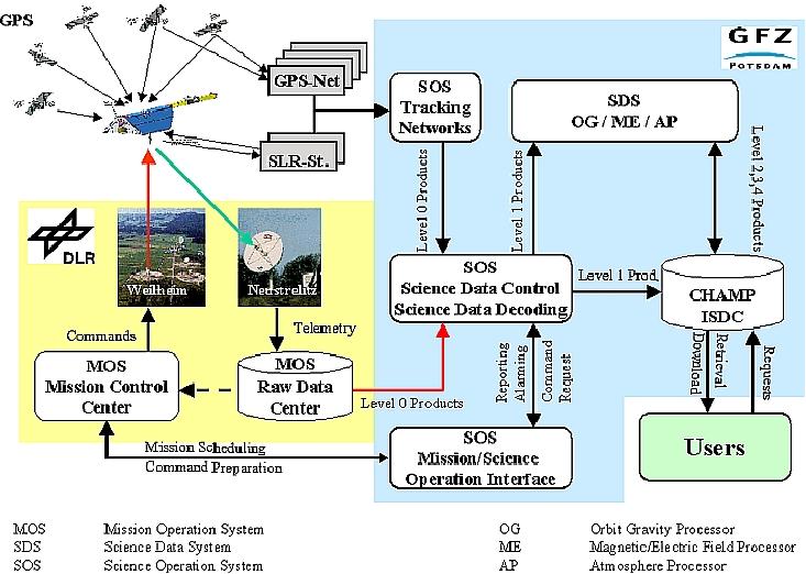
The CHAMP mission (monitoring and control) is being operated at GSOC (German Space Operations Center) in Oberpfaffenhofen, Germany. The payload data are being received at the DLR Raw Data Center in Neustrelitz (also long-term storage of data).
The payload data are being analyzed at the CHAMP ISDC (Information System and Data Center), located at GFZ, Potsdam.
References
1) http://www.gfz-potsdam.de/portal/-;jsessionid...
2) http://www-app2.gfz-potsdam.de/pb1/op/champ/
3) A. Zaglauer, W. Pitz, “CHAMP-The First FLEXBUS in Orbit,” Proceedings of the 3rd International Symposium of IAA, Berlin, April 2-6, 2001, pp. 105-109
4) http://op.gfz-potsdam.de/champ/
5) Ch. Reigber, P. Schwintzer, “A Challenging Microsatellite Payload for Geophysical Research and Application,” in: Small Satellites for Remote Sensing, Space Congress '95, Bremen, May 24-25, 1995, pp. 83-89, European Space Report, Munich, 1995
6) Ch. Reigber, R. Casper, W. Päffgen, “The CHAMP Geopotential Mission,” IAA 2nd International Symposium on Small Satellites for Earth Observation, Berlin, April 12-16, 1999, pp. 25-28
7) Ch. Schmitt, H. Bauer, “CHAMP Attitude and Orbit Control System,” IAA 2nd International Symposium on Small Satellites for Earth Observation, Berlin, April 12-16, 1999, pp. 269-272
8) “A Fiery End,” GFZ, Sept. 20, 2010, URL: https://web.archive.org/web/20101003065619/http://www.gfz-potsdam.de/portal/gfz/Public+Relations/Pressemitteilungen/aktuell/100920_PM_CHAMP-End?$javascript=enabled
9) Information provided by Franz-Heinrich Massmann of GFZ Potsdam.
10) Information provided by Markus Rothacher of GFZ Potsdam
11) J. Wickert, G. Beyerle, S. B. Healy, S. Heise, G. Michalak, M. Rothacher, T. Schmidt, “GPS based atmospheric sounding with CHAMP: Results achieved after 4 years,” EUMETSAT Meteorological Satellite Conference, Dubrovnik, Croatia, Sept. 19-23, 2005
12) “GPS Receiver TRSR-2,” URL: http://op.gfz-potsdam.de/champ/systems/index_SYSTEMS.html
13) Oliver Montenbruck, Remco Kroes, “In-flight performance analysis of the CHAMP BlackJack GPS Receiver ,” GPS Solutions, Volume 7, No 2. August 2003, pp. 74-86
14) Information provided by T. P. Yunck of NASA/JPL
15) T. Meehan, C. Duncan, et al., “GPS On A Chip - An Advanced GPS Receiver for Spacecraft,” Proceedings of the ION GPS-97 Conference, Sept. 16-19, 1997, Kansas City, MO, pp. 1509-1517
16) A. Reichert, T. Meehan, T. Munson, ““Toward Decimeter-Level Real-Time Orbit Determination: A Demonstration Using the SAC-C and CHAMP Spacecraft,” ION-GPS 2002, Portland, OR, Sept. 24-27, 2002
17) P. Touboul, B. Foulon, G. M. LeClerc, “STAR, The Accelerometer of the Geodesic Mission CHAMP,” Proceedings of the 49th IAF Congress, Melbourne, Australia, Sept. 28 - Oct. 2, 1998, IAF-98-B.3.07
18) “Ultra-Sensitive Accelerometry and Space Projects,” URL: http://www.onera.fr/dmph-en/ultra-sensitive-accelerometry/earth-planets-observation.php
19) J. L. Jørgensen, “In Orbit Performance of a fully Autonomous Star Tracker,” 4th ESA International Conference on Spacecraft Guidance, Navigation and Control Systems, Oct. 18-21, 1999, pp. 103-110, ESA/ESTEC, Noordwijk, The Netherlands, (ESA SP-425, Feb. 2000)
20) http://iris.iau.dtu.dk/research/ASC/forside.html
21) http://www.amptek.com/didm.html
22) http://op.gfz-potsdam.de/champ/systems/main_SYSTEMS.html
23) http://www-app2.gfz-potsdam.de/pb1/op/champ//
The information compiled and edited in this article was provided by Herbert J. Kramer from his documentation of: ”Observation of the Earth and Its Environment: Survey of Missions and Sensors” (Springer Verlag) as well as many other sources after the publication of the 4th edition in 2002. - Comments and corrections to this article are always welcome for further updates.(eoportal@symbios.space)