CIRiS (Compact Infrared Radiometer in Space)
EO
NASA
Operational (nominal)
Quick facts
Overview
| Mission type | EO |
| Agency | NASA |
| Mission status | Operational (nominal) |
| Launch date | 05 Dec 2019 |
| CEOS EO Handbook | See CIRiS (Compact Infrared Radiometer in Space) summary |
CIRiS (Compact Infrared Radiometer in Space)
Instrument Launch Mission Status References
Ball Aerospace has been selected by NASA's Science Mission Directorate to build and test a complete radiometric instrument on a Cubesat for a space mission under the InVEST (In-Space Validation of Earth Science Technologies) program. According to David Osterman, the PI of CIRiS, the on-orbit phase of the project will validate data processing algorithms and calibration, and also verify radiometric performance. Potential future applications of Cubesats with the CIRiS design include studies of the hydrological cycle, urban climate and extreme storms; measurements to improve climate modeling; and support to land use management via vegetation monitoring and water absorption mapping. 1)
The mission objective is technology demonstration for improved on-orbit radiometric calibration. The CIRiS calibration approach uses a scene select mirror to direct three calibration views to the focal plane array and to transfer the resulting calibrated response to earth images. The views to deep space and two blackbody sources, including one at a selectable temperature, provide multiple options for calibration optimization. Two new technologies, carbon nanotube blackbody sources and microbolometer focal plane arrays with reduced pixel sizes, enable improved radiometric performance within the constrained 6U CubeSat volume. 2)
The CIRiS mission is envisioned as a calibration laboratory in space to test source viewing order and timing. Furthermore, it demonstrates the use of vertically aligned carbon nanotubes as a very high emissivity source and an uncooled microbolometer. Due to the focus on instrument calibration, this program spends a significant amount of time in the thermal vacuum chamber to attain a good quality ground calibration. The resulting test plan is presented, along with the plan as implemented, and several lessons learned from the process. 3)
CIRiS is an instrument developed by Ball Aerospace for LWIR (Long Wave Infrared) radiometric imaging from space in a CubeSat-compatible configuration. With its own on-board calibration system, CIRiS is capable of a wide range of scientific, operational and commercial application. Specialization for a given application is facilitated by a modular instrument design enabling changes to a subsystem without impacting the overall architecture. CIRiS has been integrated to a 6U CubeSat spacecraft bus for demonstration in a LEO (Low Earth Orbit) mission and completed a Thermal Vacuum (TVAC) campaign in this integrated configuration. TVAC activities included transfer of calibration to two on-board calibration sources, environmental testing, and instrument performance characterization.
Note: The instrument and the spacecraft have the same name, CIRiS.
CIRiS Instrument
The CIRiS instrument enables on-orbit selection of calibration parameters including source temperatures, viewing sequence, timing and other variables. The primary objective of the CIRiS mission is to demonstrate new technologies for radiometric calibration on a CubeSat. A secondary objective is to identify effective methods to achieve high radiometric and calibration performance in an entirely uncooled CubeSat-compatible instrument imaging in the thermal infrared wavelength range.
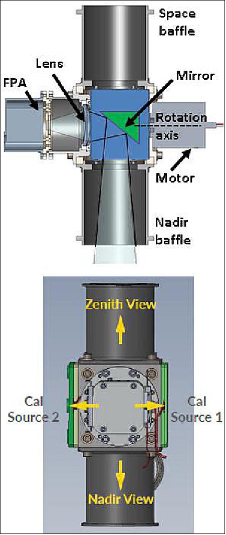
CIRiS images in three infrared bands (Table 1), which may be scanned across the Earth from LEO in pushbroom mode to generate three parallel image sets. A scene select mirror enables direction of the FPA Field of View (FOV) in four orthogonal directions (Figure 1), comprising one nadir view for science imaging, and three views for on-orbit calibration. The calibration views are to: 1) deep space 2) an on-board source at a selectable and controlled temperature and 3) an on-board source at the instrument temperature, also controlled. Calibration in space may use any subset or sequence of the three calibration views. The on-board sources are themselves calibrated on the ground using a NIST (National Institute of Science and Technology) traceable source prior to launch.
F number | F/1.8 |
Angular resolution | 0.00122 radians |
FOV (Filed of View) | 12.2º x 9.2º |
GSD (Ground Sample Distance, at 500 km altitude) | 0.166 km |
FPA (Focal Plane Array) format | 640 x 480 |
FPA NEDT (F/1,300 K) | < 50 mK |
Band 1 | 7.4 µm to 13.72 µm |
Band 2 | 9.85 µm to 11.35 µm |
Band 3 | 11.77 µm to 12.6 µm |
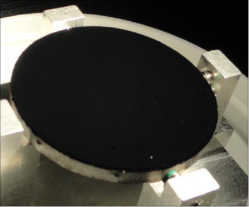
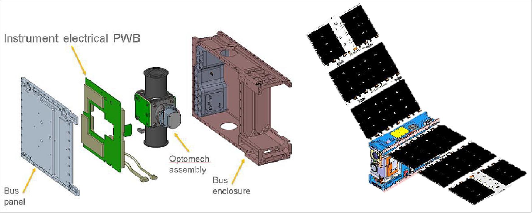
New technologies in CIRiS include a recent model 640 x 480 uncooled microbolometer FPA (Focal Plane Array) with improved radiometric stability, and high emissivity, flat panel, CNT (Carbon Nanotube) calibration sources (Figure 2). Multiple thermally controlled zones address the challenge of temperature stabilization from LEO with a significant limit on insulation volume. The single electronics board performs all instrument electronics functions (Figure 3). The spacecraft solar arrays and battery capacity are sufficient for day and night operation. Multiple CIRiS instruments deployed on constellations of CubeSats or smallsats would be capable of observations with short revisit times and/or high levels of global coverage. Applications that could benefit include volcano monitoring, evapotranspiration measurement for monitoring irrigation sufficiency and drought prediction, and disaster detection and monitoring.
Due to the calibration focus of the CIRiS mission, significant effort was put into the calibration and related testing for this CubeSat. The resulting test program is a mix between the testing typical of a larger NASA program and the minimum required for a CubeSat secondary launch.
CIRiS Test Plan
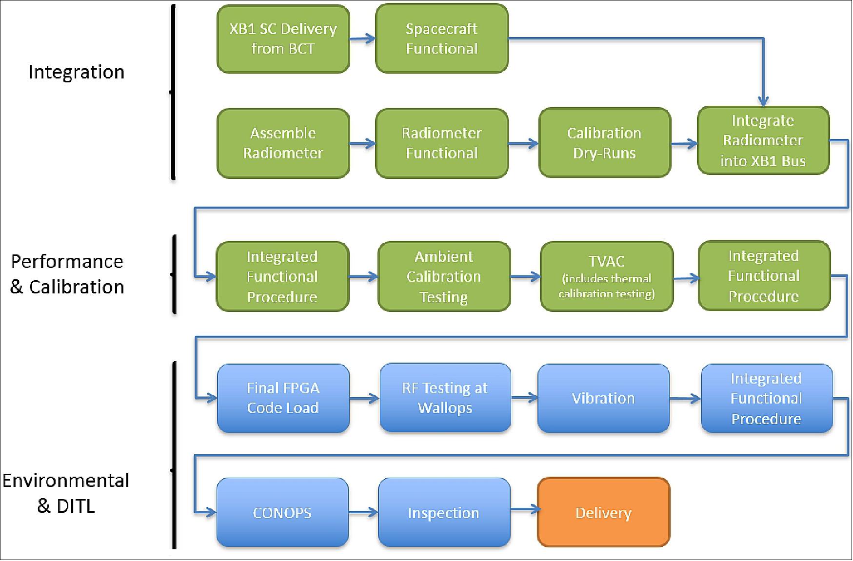
The standard plan of “do no harm” for secondary payloads is only to protect the primary payload and does not ensure survival or performance of the CIRiS spacecraft. CIRiS is a calibration testbed, making the calibration portion of the test program especially important. The overall integration and test flow for CIRiS is shown in Figure 4.
The instrument integration phase started working with the spacecraft early in the process. This was enabled by procurement of a spacecraft avionics EDU that matches the power and data interfaces of the flight spacecraft, and the command interface of the flight system. Throughout the instrument development and build phase the spacecraft EDU electronics were used. This was used as early as the initial instrument control electronics board testing. Through integration it was used to wring out any interface issues early and resulted in a very quick and trouble-free integration of the instrument to the spacecraft.
The functional tests for the spacecraft, instrument, and combined flight system were developed to test as many of the functions in the system as possible in ambient (and gravity) while minimizing the support equipment required to perform the tests. These tests were run multiple times to performance can be trended through the I&T process and through environmental tests. These procedures were also written so that sections could be used in TVAC (Thermal Vacuum ) without significant new writing. All of the procedures and the test order used in TVAC were dry-run prior to the TVAC test to minimize the time spent in the TVAC chamber (when time is expensive) as much as possible.
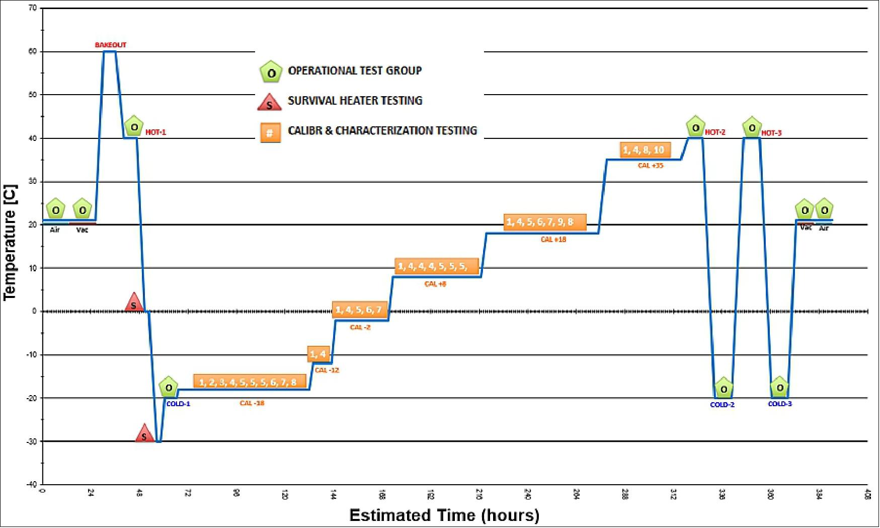
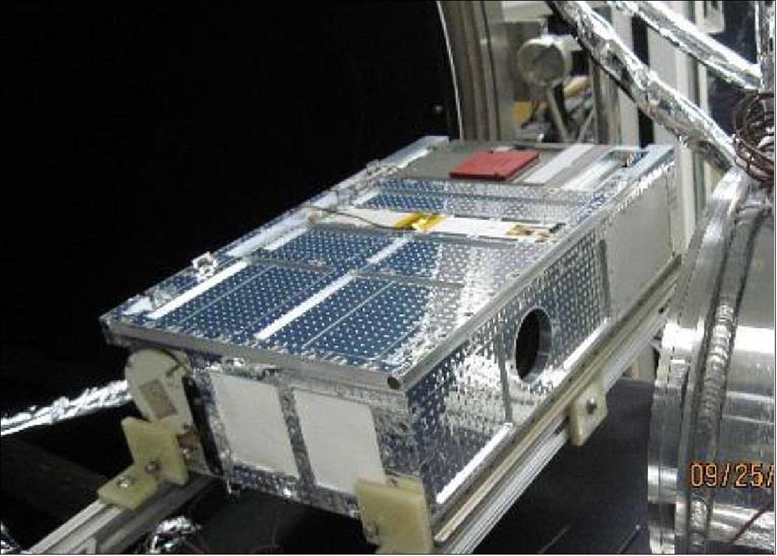
Due to the importance of the thermal environment for calibration and atmospheric absorption in the bands CIRiS operates, the calibration program is executed in a TVAC chamber. Furthermore, the calibration program uses a blackbody source that that requires vacuum and that was calibrated by NIST. The planned TVAC profile is shown in Figure 5, and executes one cycle at survival temperatures to ensure heaters activate properly. This is followed by a series of steps where calibration is performed at a range of temperatures that span the expected possible operational temperatures on-orbit. Finally, two thermal cycles are performed at operational temperature limits. The integrated spacecraft with all flight thermal coatings is shown in Figure 6, just prior to entering the TVAC chamber. The cylinder on the right edge of the photo is the blackbody calibration source.
The next test in the flow is a ground station compatibility test. This test is performed to validate the communication system end-to-end using the actual ground station and the ground command system. The test is performed at NASA Wallops using the 18m UHF dish that will be used for flight and the same software that SDL will use to command the system during flight. This test was successful and found several documentation errors that were corrected prior to launch, and would have significantly slowed the commissioning of the spacecraft after launch.
Vibration testing follows the ground station compatibility test, and is written around the requirements flowed from our launch provider. The launch for CIRiS is a SpaceX Dragon capsule to the International Space Station (ISS), then gets mounted to the exterior of a Cygnus capsule, and deployed at ~500 km altitude. The test set is minimal due to the benign launch environment. Random vibration levels are set higher than the measured launch levels to provide an adequate structural test.
The final testing is day in the life (DITL) and final inspection where mass properties are measured. The DITL test is aimed to provide a final verification of the macros saved in spacecraft memory and the full command sequence for the activities planned on-orbit. This test will involve the spacecraft operators at SDL/USU (Space Dynamics Laboratory/Utah State University) as well as the CIRiS team at Ball to help identify any issues with the operations process prior to launch. The spacecraft will be delivered to the launch integrator on 2 October 2019.
Launch
The CIRiS 6U CubeSat was launched on the SpaceX Dragon flight (CRS-19) on 5 December 2019 (17:29:24 UTC) from SLC -40 (Space Launch Complex 40) at Cape Canaveral Air Force Station, Florida. 4)
Orbit: Near circular orbit, altitude of ~400 km, inclination = 51.6º.
Secondary Payloads
The following ELaNa 25B and 28 technology and demonstration missions were launched on this resupply flight.
AzTechSat-1
A 1U CubeSat technology demonstration developed by UPAEP (Universidad Popular Autonoma del Estado de Puebla) in Puebla, Mexico, that will use the low-Earth orbit satellite constellation Globalstar for satellite phone and low-speed data communications.
CryoCube-1
A 3U CubeSat developed at NASA/KSC to perform cryogenic fluid management experiments. The 3U Cubesat features deployable solar arrays, which double as a solar heat shield. A second deployable heat shield will block earth's infrared radiation. Active doors will expose the cryogenic oxygen tank to space during eclipse phases.
SORTIE
(Scintillation Observations and Response of The Ionosphere to Electrodynamics). The SORTIE 6U CubeSat mission is led by ASTRA LLC (Atmospheric & Space Technology Research Associates). The team is composed of ASTRA, COSMIAC, AFRL, University of Texas at Dallas and Boston College. COSMIAC will be the satellite integrator. The mission is to collect data over the course of 6 months, which will allow scientists to describe the distribution of wave-like structures in the plasma density of the ionospheric F-region and to connect these variations to wave sources in the troposphere and in the high latitude thermosphere.
CIRiS
(Compact Infrared Radiometer in Space). A 6U CubeSat of USU (Utah State University), Logan, UT. The objective is to raise the technology readiness level of the new uncooled detector and carbon nanotube source from level 5 to 6, enabling future reduced cost missions to study the hydrologic cycle, characterization of ocean/atmosphere interactions vegetation and land use management. The IR radiometer features a spectral range from 7-13 µm.
EdgeCube
A 1U CubeSat of Sonoma State University. The objective is to take global measurements of the red edge that monitors a sharp change in leaf reflectance in the range 680 - 750 nm from changes in vegetation chlorophyll absorption and mesophyll scattering due to seasonal leaf phenology or stress. The payload consists of six pairs of photo-sensors and filters that are pointed normal to the spin axis to scan the Earth.
Dragon will join three other spacecraft currently at the station. On 8 December (Sunday), ESA astronaut Luca Parmitano and NASA flight engineer Drew Morgan will man the space station’s Canadian-built robot arm to capture the Dragon supply ship. The robotic arm will position the Dragon spacecraft on the station’s Harmony module, where astronauts will open hatches and begin unpacking the cargo inside the supply ship’s internal compartment.
Mission Status
• The CIRIS CubeSat was deployed in its final orbit on 1 February 2020 (after stay on the ISS and transfer into a higher orbit). The orbit is at an altitude of 470 km and the inclination is 52º. 5)
- CIRIS exercised subsystems: telemetry, focal plane, scene select mirror.
- Scanned through three calibration views; imaged all calviews.
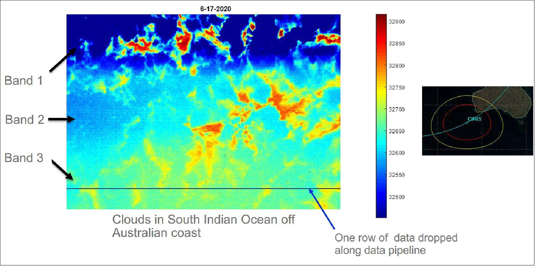
- Taken first Earth images through science port.
- Working to improve communication efficiency with spacecraft, especially dropped data.
Next steps:
- Complete commissioning of all instrument functions.
- Characterize calibration performance.
- Optimize calibration using characterization results.
- Acquire calibrated Earth images.
CIRiS Test Changes
Several changes have taken place over the life of the program, with the two major changes being a change in launch provider that changes structural testing and battery testing, and an anomaly in TVAC that forced a test re-plan while in the chamber.
The launch vehicle uncertainty is something that most CubeSat programs face, and CIRiS had originally planned for it by writing a vibration test procedure that included all possible tests with levels from GSFC-STD-7000. This was aimed at a launch that did not involve ISS. When the launch was changed to one that involved ISS, the vibration test procedure required updates since many of the tests are not required, but the levels are also uncertain due to the additional requirement of review by the NASA Safety Board. The battery test requirements are different than the spacecraft test requirements. With ISS involved, CIRiS also needs to add battery testing to the plan since the CIRiS battery is 176 Whrs, significantly above the capacity ISS allows without special testing. Additional battery charge and discharge testing is now planned following vibration testing to satisfy these additional requirements.
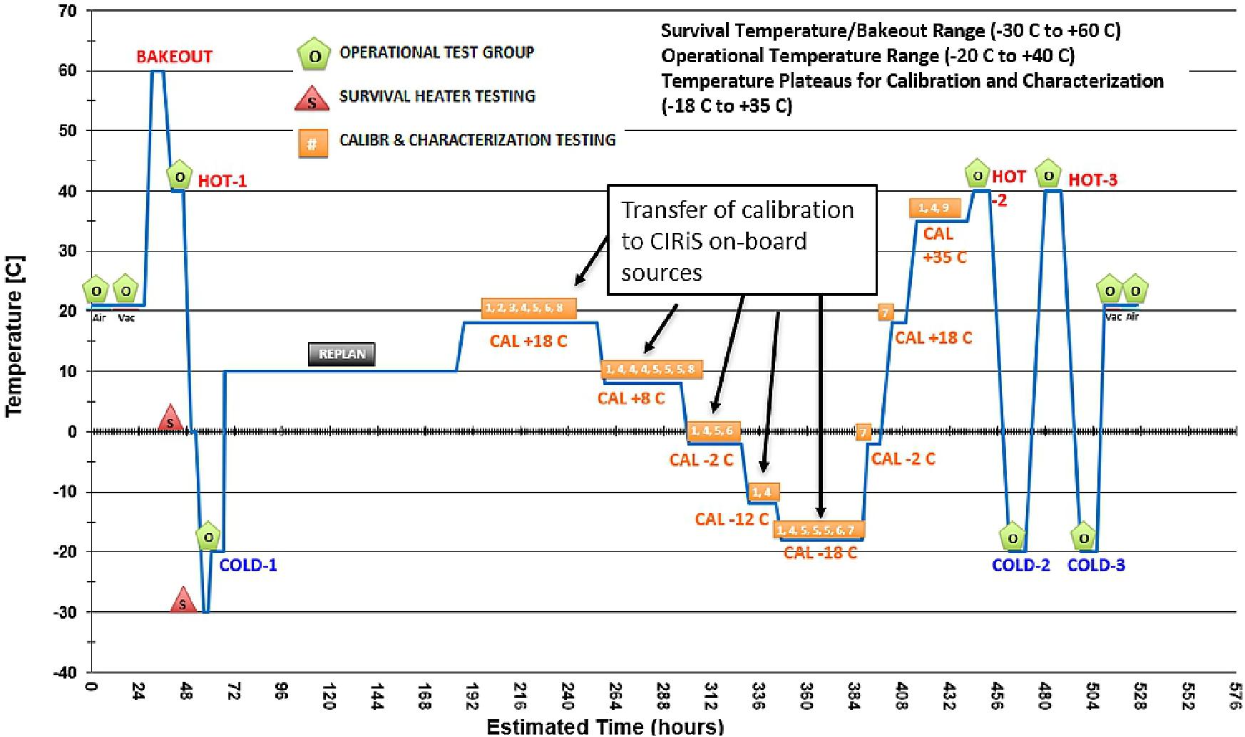
The second major change to the test program came in the TVAC chamber when the calibration motor home sensor stopped working at low temperatures. This issue was found the first time the spacecraft went cold in the chamber, and a motor movement error reported during the functional test suite. Experimentation found that the home switch was the source of the problem, and further changes in temperature identified the temperature at which the switch stopped working. This was an issue because the FPGA code did not allow the motor to move without a valid home command. A scheme was devised where a valid home command was issued at warm temperatures, then the instrument remained powered-on for the remainder of the test so the command was still valid. This required a change in the test profile (Fig. 7), that started on a warm temperature plateau to enable a valid home command. This procedure was adopted because breaking the test setup to open the chamber and make a hardware or FPGA code change would have caused several days of delay.
The process of commanding the motor movements without a working home switch also uncovered some inconsistency in the position that the home switch reported at different temperatures. It was found that counting motor steps and verifying position by scanning the nadir aperture were a more reliable and consistent method of positioning the scene select motor. The FPGA code was updated after the TVAC test to allow for movement without a valid home command to ensure that the motor can be moved when on-orbit, even if the temperature is lower than predicted, and lower than the home switch can tolerate.
Lessons Learned
The CIRiS program is the first CubeSat program executed at Ball Aerospace. Processing exist to enable this level of rigor. Three key lessons learned are presented here to enable better execution of future missions:
First, not having a launch makes design difficult, and makes getting resources difficult. This is a common problem faced by CubeSat programs, especially those using NASA’s ELaNa (Educational Launch of Nanosatellites) program, where the launch is often not applied for until the program is won, and the launch award is not made until after the design phase is complete. Ball handled this by designing for the GSFC-STD-7000 structural environment, but there were implications beyond the structural environment. The program was originally not slated to pass through ISS, and the late decision to use an ISS launch necessitated additional battery testing and approval of waivers by the NASA Safety Review Board. These changes added significant effort to the program that was not planned. In hindsight, the program would have performed the extra battery tests during the build phase to keep the launch options open and reduce additional effort late in the program. The other consequence of not having a launch date is the management challenge: without a firm deadline, things are not considered as high a priority. This is especially difficult for a program with mostly part-time help. Setting a launch date earlier in the program (even if it isn’t solidified) helps drive program execution and maintain priority with employees and management.
Second, CIRiS was executed with a small team to keep turnover low and to keep the few people employed at a higher percent of their time. None were full-time on the project. This small team execution was very efficient for the design and build phases of the program but was a challenge for the long (21 day) TVAC test campaign. To staff the TVAC test 24 hours per day required the addition of 4 people to the CIRiS roster, and even with that the test was executed with only one person per shift. This forced the I&T lead to work very long days to cover the shift changes at the beginning and end of the normal work day, and to cover odd hours when questions arose. A better approach would have been to add an I&T engineer earlier in the program so two people had extensive experience operating the system and could cover the two shift changes and split time answering questions at odd hours.
The third lesson is related to the second: write good test procedures, even if process does not require it. This helps extend the team with minimal training, and reduces errors through the test campaign. CIRiS did this, and it proved invaluable during TVAC testing when staff from outside the core team were required. It was also valuable for night shift when only one person was awake to run tests. The original program plan did not write complete step-by-step procedures, but it became evident that it would be necessary for TVAC, and it proved critical that detailed procedures were available.
In summary, Ball has processes in place that enable the low-cost execution of a CubeSat mission, and the experience to understand where extra effort is worthwhile. Program execution used a small team with a mix of younger engineers with energy, creativity, and a desire to learn, and seasoned veterans to help identify best practices and where problems might arise. This along with a thorough test program helped ensure a quality product that is ready for launch.
CIRiS (Compact Infrared Radiometer in Space)
CIRiS is an uncooled imaging infrared (7.5 µm to 13 µm) radiometer designed for high radiometric performance from LEO on a 6U CubeSat. The CIRiS design is based on a Ball aircraft-mounted instrument with modifications to improve radiometric uncertainty in the space environment. A high-emissivity blackbody source coated with carbon nanotubes reduces error in on-board calibration. Algorithms compensate the detector signal for changing external temperatures addressing another source of uncertainty. The CIRiS mission will enable constellations of simple, inexpensive Cubesats to replace larger more complex instruments for multiple applications in scientific research and land use management. 6)
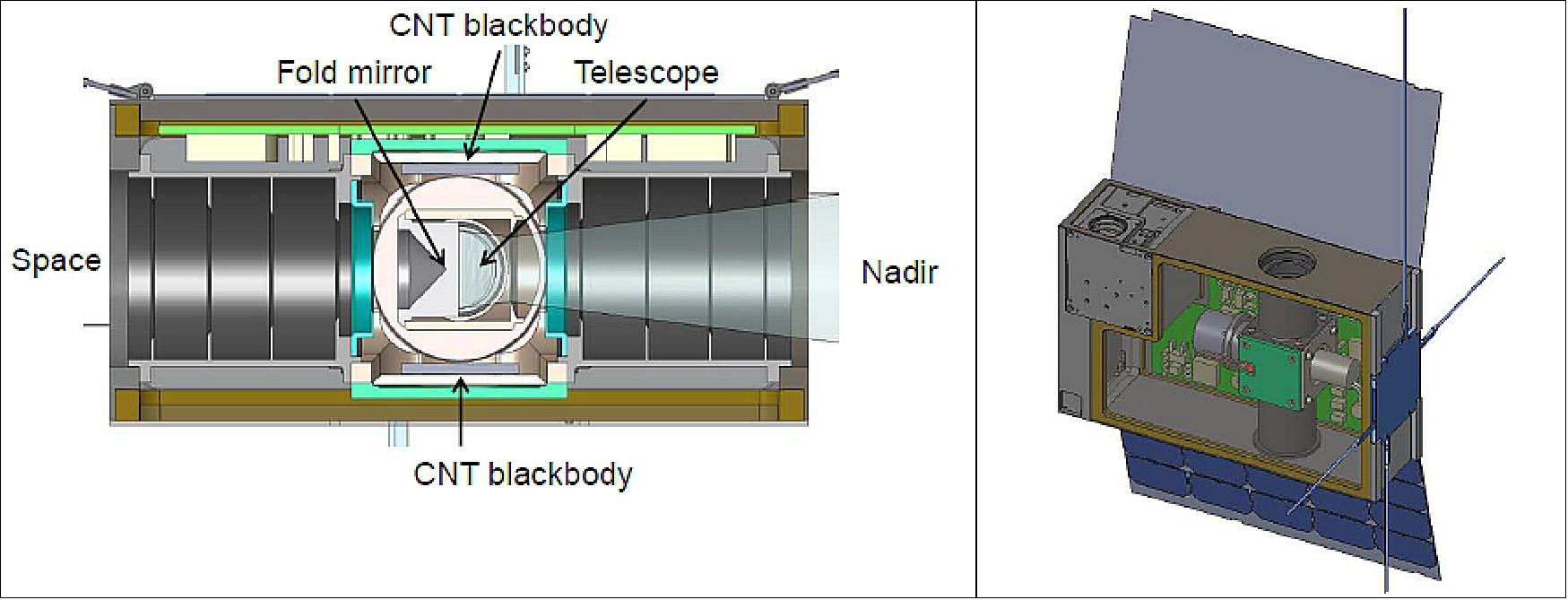
Ball's first flight of a system employing VACNT (Vertically Aligned Carbon Nanotubes) blackbodies is the CIRiS 6U CubeSat mission expected to launch in 2018. The CIRiS calibration approach uses a scene select (fold) mirror to direct three calibration views to the focal plane array and to transfer the resulting calibrated response to earth images. The views to deep space and two blackbody sources, including one at a selectable temperature, provide multiple options for calibration optimization. Both blackbodies utilize the VACNT technology developed on Ball’s various IRAD (Internal Research and Development) efforts. One blackbody is thermally connected to the spacecraft structure while the other can be controlled up to 20 K above ambient. The scene select mirror is in the path and at the same angle for both imaging and calibration so its transmission and polarization effects are eliminated. Figure 9 shows two views of the CIRiS optical system and spacecraft. 7)
References
1) ”Ball Aerospace to Implement Radiometer Mission for NASA Earth Science Cubesat Program,” PRNewswire, Dec. 16, 2015, URL: http://www.prnewswire.com/news-releases/ball-aerospace-to-implement-radiometer-mission-for-nasa-earth-science-cubesat-program-300193466.html
2) D. P. Osterman, S. Collins, J. Ferguson, W. Good, T. Kampe, R. Rohrschneider, R. Warden, “CIRiS: Compact Infrared Radiometer in Space”,Proceedings of SPIE 9978, 'CubeSats and NanoSats for Remote Sensing,' September 19, 2016, doi:10.1117/12.2238999
3) ”Reuben R. Rohrschneider, David P. Osterman, Michael Veto, Alfonso Amparan, Alia Ghandour, Patrick Kerrigan, Gretchen Reavis, Joseph Necas, and Robert Warden,”Ground Testing a LWIR Imaging Radiometer for an Upcoming SmallSat Mission,” Proceedings of the 33rd Annual AIAA/USU Conference on Small Satellites, August 3-8, 2019, Logan, UT, USA, paper: SSC19-IV-07, URL: https://digitalcommons.usu.edu/cgi/viewcontent.cgi?article=4379&context=smallsat
4) ”SpaceX Dragon Heads to Space Station With NASA Science,” NASA News, 5 December 2019, URL: https://www.jpl.nasa.gov/news/news.php?release=2019-239
5) David Osterman, Team: A. Amparan, A. Ghandour, T. Kampe, P. Kerrigan, J. Necas, D. Piqueira, G. Reavis, R. Rohrschneider, M. Veto, R. Warden, ”CIRiS: Compact Infrared Radiometer in Space,” June 23, NASA ESTO 23 June 2020, URL: https://esto.nasa.gov/wp-content/uploads/2020/07/Osterman-CIRiS.pdf
6) ”Four Projects Awarded Funding Under the In-Space Validation of Earth Science Technologies (InVEST) Program,” NASA 2015 InVEST Awards, URL: https://esto.nasa.gov/files/solicitations/INVEST_15/ROSES2015_InVEST_A42_awards.html
7) John C. Fleming, Sandra Collins, Beth Kelsic, Nathan Schwartz, David Osterman, Bevan Staple, ” Advanced On-Board Calibration of Space Systems Using a Carbon Nanotube Flat-Plate Blackbody,” 33rd Space Symposium, Colorado Springs, Co, USA, April 3-6, 2017
The information compiled and edited in this article was provided by Herbert J. Kramer from his documentation of: ”Observation of the Earth and Its Environment: Survey of Missions and Sensors” (Springer Verlag) as well as many other sources after the publication of the 4th edition in 2002. - Comments and corrections to this article are always welcome for further updates (eoportal@symbios.space).