EO
ESA
Atmosphere
Ocean
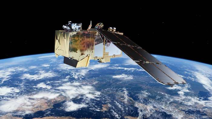
Sentinel-2 is a constellation of two optical imaging satellites, which are a part of Copernicus - the European Union’s Earth observation program. Three identical satellites comprise the Sentinel-2 constellation at present: Sentinel-2A (launched 2015), Sentinel-2B (2017), and Sentinel-2C (2024). The orbits of the satellites are coordinated to optimise coverage and revisit time.
Quick facts
Overview
| Mission type | EO |
| Agency | ESA, COM |
| Mission status | Operational (extended) |
| Launch date | 23 Jun 2015 |
| Measurement domain | Atmosphere, Ocean, Land |
| Measurement category | Multi-purpose imagery (ocean), Radiation budget, Multi-purpose imagery (land), Vegetation, Albedo and reflectance |
| Measurement detailed | Ocean imagery and water leaving spectral radiance, Land surface imagery, Vegetation type, Fire fractional cover, Earth surface albedo, Leaf Area Index (LAI), Land cover, Normalized Differential Vegetation Index (NDVI), Photosynthetically Active Radiation (PAR), Fraction of Absorbed PAR (FAPAR), Soil type, Upwelling (Outgoing) spectral radiance at TOA |
| Instruments | MSI (Sentinel-2) |
| Instrument type | High resolution optical imagers |
Related Resources
Summary
Mission Capabilities
Data products from Sentinel-2 satellites are used for a wide variety of applications, including precision farming, water quality monitoring, natural disaster management and methane emission detection. Sentinel-2 provides particularly useful information for monitoring natural ecosystems, as it can differentiate between vegetation types and measure biophysical variables such as leaf area index, leaf chlorophyll content, and leaf water content.
The Sentinel-2 satellites are identical and have a Multispectral Instrument (MSI) onboard. This instrument comprises a three-mirror anastigmat (TMA) telescope to collect and focus light, a beam splitter to separate visible and near-infrared (VNIR) from short-wave infrared (SWIR) light, two focal planes with 12 detectors on each for the two different radiation types, a diffuser for radiometric calibration, and a calibration and shutter mechanism (CSM) to protect the instrument from sunlight at launch.
Performance Specifications
MSI has 13 spectral bands: four visible bands (one at 60 m resolution and three at 10 m resolution); five near-infrared (NIR) bands (one at 10 m resolution and four at 20 m resolution); two shortwave infrared (SWIR) bands at 20 m resolution; and two additional bands—one for water vapor detection and one for cirrus detection—both with a 60 m resolution.
The Sentinel-2 satellites have a swath width of 290 km, and together achieve a five-day revisit time. The two satellites follow the same sun-synchronous orbit with an inclination of 98.6° but are 180° out of phase. They orbit at an altitude of 786 km with a period of 101 minutes.
Space and Hardware Components
Sentinel-2 uses the AstroBus-L of Airbus Defence & Space, a Low Earth Orbit (LEO) optimised platform, providing stability and power for the mission's imaging equipment and communications systems. The total mass of Sentinel-2 is approximately 1,200 kg. The platform provides X-band MSI data downlink at 560 Mbit/s and telemetry, tracking, and command (TT&C) data link with 64 kbit/s uplink and 2 Mbit/s downlink.
Overview
Sentinel-2 is a multispectral operational imaging mission within the European Union's Copernicus Programme, jointly implemented by the EC (European Commission) and ESA (European Space Agency) for global land observation at high resolution and revisit capability to provide enhanced continuity of data. Sentinel-2 data covers vegetation, soil and water cover for land, inland and coastal waters, as well as cloud screening and atmospheric corrections. 1) 2) 3) 4) 5) 6) 7) 8)
To meet user needs, the Sentinel-2 satellite data supports the operational generation of the following high-level products:
• Generic land cover, land use and change detection maps (e.g. CORINE land cover maps update, soil sealing maps, forest area maps)
• Maps of geophysical variables (e.g. leaf area index, leaf chlorophyll content, leaf water content).
The mission is dedicated to the full and systematic coverage of land surface (including major islands) globally with the objective to provide cloud-free products typically every 15 to 30 days over Europe and Africa. This objective is achieved thanks to the 5-day geometric revisit time of the constellation of two operational satellites.
The following list summarises the top-level system design specifications derived from the user requirements as defined by the GMES (Global Monitoring for Environment and Security) program (now known as Copernicus):
• Sentinel-2 will provide continuity of data for services initiated within the GSE (GMES Service Element) projects. It will establish a key European data source for the GMES Land Fast Track Monitoring Services and contribute to the GMES Risk Fast Track Services.
• The frequent revisit and high mission availability goals call for 2 satellites in orbit at a time, each with a 290 km wide swath using a single imaging instrument
• Continuous land + islands carpet mapping imaging within the latitude range of -56º to +83º (the selected orbit excludes imagery from Antarctica)
• 10 m, 20 m, and 60 m spatial resolution (in the VNIR to SWIR spectral range) to identify spatial details consistent with 1 ha MMU (Minimum Mapping Unit)
• An accurate geolocation (< 20 m) of the data is required (without GCPs) and shall be produced automatically to meet the timeliness requirements. The geolocation accuracy of Level 1 b imagery data w.r.t. WGS-84 (World Geodetic System - 1984) reference Earth ellipsoid of better than 20 m at 2σ confidence level without the need of any ground control points.
• Very good radiometric image quality (combination of onboard absolute and on-ground vicarious calibration).
• The mission lifetime is specified as 7.25 years and propellant is to be sized for 12 years, including provision for de-orbiting manoeuvres at end-of-life.
• 2 weeks of satellite autonomy and maximum decoupling between flight operations and mission exploitation
To provide operational services over a long period (at least 15 years following the launch of the first satellites), four satellites will be developed, with nominally two satellites in operation in orbit and a third one stored on the ground as a backup.
In partnership: The Sentinel-2 mission has been made possible thanks to the close collaboration between ESA, the European Commission, industry, service providers and data users. Demonstrating Europe’s technological excellence, its development has involved around 60 companies, led by Airbus Defence and Space in Germany for the satellites and Airbus Defence and Space in France for the multispectral instruments. 10)
The mission has been supported in kind by the French space agency CNES to provide expertise in image processing and calibration, and by the German Aerospace Center DLR which provides the optical communication payload, developed by Tesat Spacecom GmbH. This piece of technology allows the Sentinel-2 satellites to transmit data via laser to satellites in geostationary orbit carrying the European Data Relay System (EDRS). This new space data highway allows large volumes of data to be relayed very quickly so that information can be even more readily available to users.
Developing Sentinel-2 has involved a number of technical challenges, from early specification in 2007 to qualification and acceptance in 2015. The satellite requires excellent pointing accuracy and stability and, therefore, high-end orbit and attitude control sensors and actuators. The multispectral imager is the most advanced of its kind, integrating two large visible near-infrared and shortwave infrared focal planes, each equipped with 12 detectors and integrating 450,000 pixels. The instrument’s optomechanical, geometric, and radiometric stability must be extremely high, to avoid image distortion and stray light effects.
Each satellite has a high level of autonomy so that it can operate without any intervention from the ground for periods of up to 15 days. This requires sophisticated autonomous failure analysis, detection and correction on board.
The ‘carpet mapping’ imaging plan requires the acquisition, storage and transmission of 1.6 TB of data per orbit. This massive data blast results from the combination of the 290 km swath with 13 spectral channels at a spatial resolution as high as 10 m.
Land in Focus
Ensuring that land is used sustainably, while meeting the food and wood demands of a growing global population is one of today’s biggest challenges. The Copernicus land service provides information to help respond to global issues such as this as well as focusing on local matters, or ‘hotspots’, that are prone to specific challenges.
Sentinel-2 can distinguish between different crop types and delivers timely data on plant indices such as leaf area index, leaf chlorophyll content and leaf water content – all of which are essential to accurately monitor plant growth. This kind of information is essential for precision farming: helping farmers decide how best to nurture their crops and predict their yield.
Alongside economic benefits, this information supports food security in developing countries. The mission’s revisit time of just five days, along with the mission’s range of spectral bands, means that changes in plant health and growth status can be easily monitored.Sentinel-2 also provides information about changes in land cover, for example due to urban growth, deforestation, and disasters.The Copernicus land service addresses five ‘pan-European’ themes covering 39 countries, including sealed soil (imperviousness), tree cover density, forest type, and grasslands.
The mission also provides information for bathymetry, as well as for monitoring coral reefs and pollution in lakes and coastal waters at high spatial resolution with frequent coverage. The capacity for frequent coverage highlights Sentinel-2’s ability to contribute to disaster mapping and humanitarian aid work.

Table 1: Sentinel-2 mission overview and key specifications |
Spacecraft
In April 2008, ESA awarded the prime contract to Airbus Defence and Space (former EADS-Astrium GmbH) of Friedrichshafen, Germany to provide the first Sentinel-2A Earth observation satellite. In the Sentinel-2 mission program, Astrium is responsible for the satellite’s system design and platform, as well as for satellite integration and testing. Astrium Toulouse supply MSI (MultiSpectral Instrument), and Astrium Spain is in charge of the satellite’s structure pre-integrated with its thermal equipment and harness. The industrial core team also comprises Jena Optronik (Germany), Boostec (France), Sener and GMV (Spain). 11) 12) 13) 14)
Sentinel-2 uses the AstroBus-L of EADS Astrium. It is a standard modular ECSS (European Cooperation for Space Standards) satellite platform compatible with an in-orbit lifetime of up to 10 years, with consumables sizeable according to the mission needs. The platform design is one-failure tolerant and the standard equipment selection is based on minimum Class 2 EEE parts, with compatibility to Class 1 in most cases.
The AstroBus-L platform is designed for direct injection into LEO (Low Earth Orbit). Depending on the selection of standard design options, AstroBus-L can operate in a variety of LEOs at different heights and with different inclinations. An essential feature of AstroBus-L is the robust standard FDIR (Failure Detection, Isolation and Recovery) concept, which is hierarchically structured and can easily be adapted to specific mission needs.
The satellite is controlled in 3-axes via high-rate multi-head star trackers, mounted on the camera structure for better pointing accuracy and stability, gyroscopes, and a GNSS receiver assembly. The AOCS (Attitude and Orbit Control Subsystem) comprises the following elements: 18)
• A dual-frequency GPS receiver (L1/L2 code) for position and time information
• A STR (Star Tracker) assembly for precise attitude information (use of 3 STRs)
• A RMU (Rate Measurement Unit) for rate damping and yaw acquisition purposes
• A redundant precision IMU (Inertial Measurement Unit) for high-accuracy attitude determination
• Magnetometers (MAG) for Earth magnetic field information
• CESS (Coarse Earth Sun Sensors) for coarse Earth and Sun direction determination
• 4 RW (Reaction Wheels) and 3 MTQ (Magnetic Torquers)
• RCS (Reaction Control System) a monopropellant propulsion system for orbit maintenance with 1 N thrusters
The different tasks of the AOCS are defined by the following modes:
• Initial Acquisition and Save Mode (rate damping, Earth acquisition, yaw acquisition, steady-state)
• Normal Mode (nominal and extended observation)
• Orbit Control Mode (in- and out-of-plane ΔV manoeuvres).
The geolocation accuracy requirements of < 20 m for the imagery translate into the following AOCS performance requirements as stated in Table 2.
Table 2: AOCS performance requirements in normal mode |
For Sentinel-2 it was decided to mount both the IMU and the star trackers on the thermally controlled sensor plate on the MSI. So the impact of time-variant IMU/STR misalignment on attitude performance can be decreased to an absolute minimum. Furthermore, the consideration of the time-correlated star tracker noises by covariance tuning was decided.
The EPS (Electric Power Subsystem) consists of:
• Solar Array (one deployable and rotatable single wing with three panels). Total array area of 7.1 m2. Use of 2016 triple junction GaAs solar cells with integrated diodes. Total power of 2300 W (BOL) and 1730 W (EOL). The mass is < 40 kg.
• SADM (Solar Array Drive Mechanism) for array articulation. Use of a two two-phase stepper motor with µ-stepping to minimise parasitic distortions during MSI operation, motor step angle 1.5º. Mass of < 3.2 kg.
• PCDU (Power Control and Distribution Unit). PCDU with one unregulated 28 V ±4 V main power bus. Mass of < 21.6 kg; the in-orbit life is 12.25 years.
• Li-ion batteries with 8 cells in series. The total capacity of 102 Ah @ EOL. Mass = 51 kg.
The OBC is based on the ERC32 PM (Processor Module) architecture. The PLDHS (Payload Data Handling System) provides source data compression from 1.3 Gbit/s to 450 Mbit/s [state-of-the-art lossy compression (wavelet transform)].
The spacecraft mass is ~ 1200 kg, including 275 kg for the MSI instrument, 35 kg for the IR payload (optional) and 80 kg propellant (hydrazine). The S/C power is 1250 W max, including 170 W for the MSI and < 100 W for the IR payload. The spacecraft is designed for a design life of 7.25 years with propellant for 12 years of operations, including deorbiting at EOL (End of Life).
Table 3: Overview of some spacecraft parameters |
Payload data are stored in NAND flash memory technology SSR (Solid State Recorder) based on integrated CoReCi (Compression Recording and Ciphering) units of Airbus DS.
The CoReCi is an integrated image compressor, mass memory and data ciphering unit designed to process, store and format multi-spectral video instrument data for the satellite downlink. 19) 20)
The MRCPB (Multi-Résolution par Codage de Plans Binaires) compression algorithm used is a wavelet transform with bit plane coding (similar to JPEG 2000). This complex algorithm is implemented in a dedicated ASIC, with speeds of up to 25 Mpixel/s. Alternatively, this unit can be supplied with a CCSDS compression algorithm using a new ASIC developed with ESA support. The ciphering is based on the AES algorithm with 128-bit keys. The modularity of the design allows the memory capacity and data rate to be adapted by adjusting the number of compressor and memory boards used.
Launches
|
Table 4: List of Sentinel-2 launches
Orbit
All Sentinel-2 satellites operate in a sun-synchronous orbit at an altitude of 786 km, inclination of 98.5º, period of 101 minutes, and 10:30 hours LTDN (Local Time at Descending Node). This local time has been selected as the best compromise between cloud cover minimization and sun illumination.
The orbit is fully consistent with SPOT and very close to the Landsat local time, allowing seamless combination of Sentinel-2 data with historical data from legacy missions to build long-term temporal series. The two operating Sentinel-2 satellites are equally spaced (180º phasing) in the same orbital plane for a 5 day revisit cycle at the equator.
The Sentinel-2 satellites systematically acquire observations over land and coastal areas from -56° to 84° latitude including islands larger than 100 km2, EU islands, all other islands less than 20 km from the coastline, the whole Mediterranean Sea, all inland water bodies and closed seas. Over specific calibration sites, for example DOME-C in Antarctica, additional observations are made.
Mission Status
• June 23–27, 2025: During the Living Planet Symposium 2025 (LPS25), ESA celebrated the 10‑year anniversary of the Sentinel‑2 mission, which began with the launch of Sentinel‑2A on June 23, 2015. Over the past decade, Sentinel‑2 has established itself as a cornerstone for high-resolution multispectral Earth observation, delivering critical data for agriculture, forestry, land management, and environmental monitoring worldwide.
ESA provided updates on the continuity of the Sentinel-2 mission. The constellation is now fully reinforced with the launch of Sentinel‑2C on 5 September 2024, ensuring data continuity and increased revisit frequency. The ground-segment processing pipeline continues to deliver near‑real‑time biophysical indicators with consistent spatial coverage and expected radiometric performance. Calibration is complete, and data from the latest global acquisition cycle confirmed that system performance meets design expectations.
Sentinel‑2’s capabilities have expanded to address emerging environmental priorities, playing a critical role in methane emissions detection, leveraging its shortwave-infrared bands alongside advanced AI-driven image analysis to identify and quantify methane plumes globally. Operational systems like MARS‑S2L enable near‑real‑time methane monitoring, providing valuable data for climate change mitigation efforts.
Sentinel‑2 data is also increasingly used for ocean and coastal monitoring. Its high spatial resolution and multispectral imaging support detailed observation of coastal ecosystems, water quality, and land–sea interactions, areas vital for biodiversity conservation, pollution control, and understanding climate impacts on marine environments.
In parallel, the marine services community, including organisations like Mercator Ocean International, has advanced operational workflows using Sentinel‑2 MSI data for detailed coastal monitoring, bathymetry, and shallow-water ecosystem assessment.. 81) 82) 83) 84) 85)


• September 17, 2024: Sentinel-2C delivers first light imagery from around the globe, which were processed by the Copernicus Ground Segment. Initial observation locations included Seville, Spain; the coastline between Southern France and Barcelona; Los Angeles, United States; and Belize. 98)
• September 5, 2024: Sentinel-2C successfully launched onboard a Vega rocket from the European spaceport in Kourou, French Guiana. The rocket launched at 03:50 CEST (4 September 22:50 local time) and the satellite separated at approximately 04:48 CEST. Around 14 minutes later, at 05:02 CEST, ESA received the all-important signal indicating that the satellite was safely in orbit.
This marked the 22nd and final flight of the Vega rocket, which is being phased out in favour of the newer Vega-C. 97)
• August 29, 2024: Sentinel-2C is being readied for launch, and mating to the launch adapater. 95)
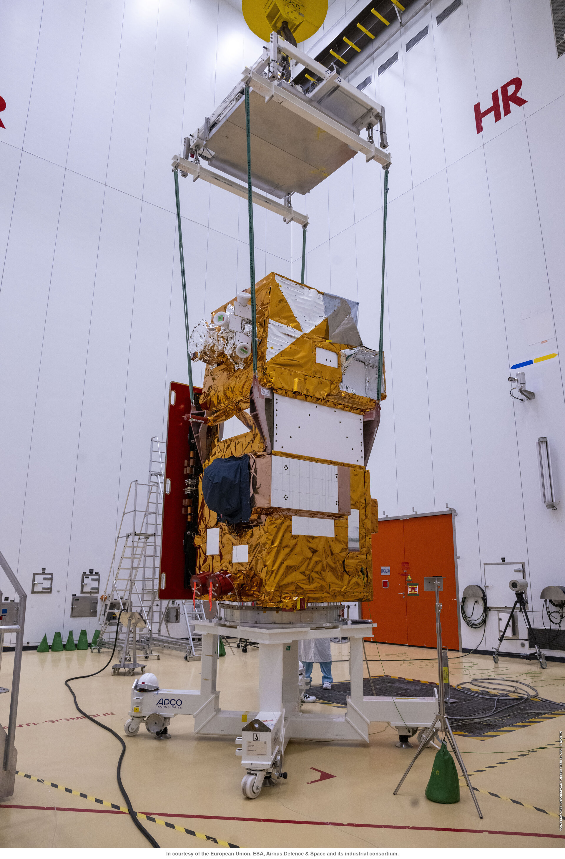
• July 22, 2024: The Sentinel-2C satellite, the third Copernicus Sentinel-2 satellite, has arrived at the European spaceport in French Guiana for liftoff on the final Vega rocket. Once in orbit, Sentinel-2C will replace its predecessor, Sentinel-2A, while Sentinel-2D will later replace Sentinel-2B. 94)
• August 9, 2021: Engineers at Airbus Defence and Space in Friedrichshafen, Germany, have now transported the Sentinel-2C satellite to IABG’s facilities in Ottobrunn for a series of exhaustive tests that will run until the end of 2021. The program includes tests that simulate noise and vibrations of liftoff, as well as the extreme temperature swings it will experience in space. It also includes tests that check correct deployment of the solar wing and electromagnetic compatibility tests in this environment.
• July 29, 2021: Airbus has finished the integration of the Copernicus Sentinel-2C satellite. It is the third of its kind and will now be shipped to Munich to undergo extensive environmental tests to prove its readiness for space. The test campaign will last until March 2022. 22)
From an altitude of 786 km, the 1.1 ton “C” satellite will enable the continuation of imaging in 13 spectral bands with a resolution of 10, 20 or 60 m and a uniquely large swath width of 290 km. Each Sentinel-2 satellite collects 1.5 TB/day, after onboard compression. The two identical satellites are flying in the same orbit but 180° apart for optimal coverage and revisit time. The satellites orbit the Earth every 100 minutes covering all of Earth’s land surfaces, large islands, and inland and coastal waters every five days.
• February 27, 2017: The ninth Vega light-lift launcher is now complete at the Spaceport, with its Sentinel-2B Earth observation satellite installed atop the four-stage vehicle in preparation for a March 6 mission from French Guiana. 23)
• January 12, 2017: Sentinel-2B arrived at Europe’s spaceport in Kourou, French Guiana on 6 January 2017 to be prepared for launch. After being moved to the cleanroom and left for a couple of days to acclimatise, cranes were used to open the container and unveil the satellite. Over the next seven weeks the satellite will be tested and prepared for liftoff on a Vega rocket. 24)
• November 15, 2016: Sentinel-2B has successfully finished its test program at ESA/ESTEC in Noordwijk, The Netherlands. The second Sentinel-2 Airbus built satellite will now be readied for shipment to the Kourou spaceport in French Guiana begin January 2017. It is scheduled for an early March 2017 lift-off on Vega. 25)
• June 15, 2016: Airbus DS completed the manufacture of the Sentinel-2B optical satellite; the spacecraft is ready for environmental testing at ESA/ESTEC. The Sentinel-1 and -2 satellites are equipped with the Tesat-Spacecom’s LCT (Laser Communication Terminal). The SpaceDataHighway is being implemented within a Public-Private Partnership between ESA and Airbus Defence and Space.
• April 27, 2015: The Sentinel-2A satellite on Arianespace’s next Vega mission is being readied for pre-launch checkout at the Spaceport, which will enable this European Earth observation platform to be orbited in June from French Guiana. With Sentinel-2A now connected to its ground support equipment and successfully switched on, the satellite will undergo verifications and final preparations for a scheduled June 11 liftoff. 27)
• April 23, 2015: The Sentinel-2A satellite has arrived safe and sound in French Guiana for launch in June. The huge Antonov cargo aircraft that carried the Sentinel-2A from Germany, touched down at Cayenne airport in the early morning of 21 April. 28)
• April 8, 2015: The Sentinel-2A satellite is now being carefully packed away in a special container that will keep it safe during its journey to the Sentinel 2 launch site in French Guiana. The satellite will have one final test, a ‘leak test’, in the container to ensure the propulsion system is tight. Bound for Europe’s Spaceport in French Guiana, Sentinel-2A will leave Munich aboard an Antonov cargo plane on 20 April. Once unloaded and unpacked, it will spend the following weeks being prepared for liftoff on a Vega rocket. 29
• February 24, 2015: Sentinel-2A is fully integrated at IABG’s facilities in Ottobrunn, Germany before being packed up and shipped to French Guiana for a scheduled launch in June 2015. 30)
• August 2014: Airbus Defence and Space delivered the Sentinel-2A environmental monitoring satellite for testing . In the coming months, the Sentinel-2A satellite will undergo a series of environmental tests at IABG, Ottobrunn, Germany, to determine its suitability for use in space. 31) 32)
• Sentinel-2 imagery in the period 2022
• Sentinel-2 imagery in the period 2021
• Sentinel-2 imagery in the period 2020
• Sentinel-2 imagery in the period 2019
Sensor Complement
MSI (Multispectral Imager)
The instrument is based on the pushbroom observation concept. The telescope features a TMA (Three Mirror Anastigmat) design with a pupil diameter of 150 mm, providing a very good imaging quality all across its wide FOV (Field of View). The equivalent swath width is 290 km. The telescope structure and the mirrors are made of silicon carbide (SiC) which allows to minimise thermoelastic deformations. The VNIR focal plane is based on monolithic CMOS (Complementary Metal Oxide Semiconductor) detectors while the SWIR focal plane is based on a MCT (Mercury Cadmium Telluride) detector hybridised on a CMOS read-out circuit. A dichroic beamsplitter provides the spectral separation of VNIR and SWIR channels. 42) 43) 44) 45) 46) 47) 48)
Airbus DS (former EADS Astrium SAS) of Toulouse is prime for the MSI instrument. The industrial core team also comprises Jena Optronik (Germany), Boostec (Bazet, France), Sener and GMV (Spain), and AMOS, Belgium. The VNIR detectors are built by Airbus DS-ISAE-e2v, while the French company Sofradir received a contract to provide the SWIR detectors for MSI.
Calibration: A combination of partial on-board calibration with a sun diffuser and vicarious calibration with ground targets guarantees a high quality radiometric performance. State-of-the-art lossy compression based on wavelet transform is applied to reduce the data volume. The compression ratio is fine tuned for each spectral band to ensure that there is no significant impact on image quality.
The observation data are digitised on 12 bit. A shutter mechanism is implemented to prevent the instrument from direct viewing of the sun in orbit and from contamination during launch. The average observation time per orbit is 16.3 minutes, while the peak value is 31 minutes (duty cycle of about 16-31%).
Table 5: MSI instrument parameters |
Spectral bands: MSI features 13 spectral bands spanning from the VNIR (Visible and Near Infrared) to the SWIR (Short-Wave Infrared), featuring 4 spectral bands at 10 m, 6 bands at 20 m and 3 bands at 60 m spatial sampling distance (SSD).
Table 6: Specification of VNIR and SWIR FPAs 49) |
Spectral band | Centre Wavelength (nm) | Bandwidth (nm) | Spatial Resolution (m) | Mission Objective / Calibration Purpose | Emerging Applications |
|---|---|---|---|---|---|
B1 | 443 | 20 | 60 | Aerosol correction | - |
B2 | 490 | 65 | 10 | Blue band, aerosol correction, water surfaces | Coastal water quality monitoring (0.49–0.56 µm) |
B3 | 560 | 35 | 10 | Green band, vegetation/chlorophyll | Coastal and aquatic ecosystem studies (0.56–0.66 µm) |
B4 | 665 | 30 | 10 | Red band for vegetation & land cover | Coastal monitoring, land-sea interaction (0.65–0.68 µm) |
B5 | 705 | 15 | 20 | Vegetation red-edge | - |
B6 | 740 | 15 | 20 | Vegetation red-edge | - |
B7 | 775 | 20 | 20 | Vegetation red-edge | - |
B8 | 842 | 115 | 10 | NIR calibration band | - |
B8a | 865 | 20 | 20 | Narrow NIR | - |
B9 | 940 | 20 | 60 | Water vapour correction | - |
B10 | 1375 | 20 | 60 | Cirrus detection | - |
B11 | 1610 | 90 | 20 | SWIR for vegetation & soil moisture | Methane emission detection (1.56–1.66 µm) |
B12 | 2190 | 180 | 20 | Vegetation, soil & water content | Methane emission detection (2.09–2.29 |
The filter-based pushbroom MSI instrument features a unique mirror silicon carbide off-axis telescope (TMA) with a 150 mm pupil feeding two focal planes spectrally separated by a dichroic filter. The telescope comprises three aspheric mirrors: M2 mirror is a simple conic surface, whereas the other mirrors need more aspherisation terms. The spectral filtering onto the different VNIR and SWIR spectral bands is ensured by slit filters mounted on top of the detectors. These filters provide the required spectral isolation.
CMOS and hybrid HgCdTe (MCT) detectors are selected to cover the VNIR and SWIR bands. The MSI instrument includes a sun CSM (Calibration and Shutter Mechanism). The 1.4 Tbit image video stream, once acquired and digitised, is compressed inside the instrument.
The instrument carries one external sensor assembly that provides the attitude and pointing reference (star tracker assembly) to ensure a 20 m pointing accuracy on the ground before image correction.
The detectors are built by Airbus Defence and Space-ISAE-e2v: they are made of a CMOS die, using 0.35µm CMOS process, integrated in a ceramic package. The VNIR detector has ten spectral bands, two of them featuring an adjacent physical line allowing TDI operating mode, with digital summation performed at VCU (Video and Compression Unit) level. On-chip analog CDS (Correlated Double Sampling) allows a readout noise of the order of 130 µV rms. For each detector, the ten bands are read through 3 outputs at a sample rate of 4.8MHz. The detector sensitivity has been adjusted for each band through CVF (Charge to Voltage conversion Factor) in view of meeting SNR specifications for a reference flux, while avoiding saturation for maximum flux. A black coating deposition on the non-photosensitive area of the CMOS die is implemented to provide high straylight rejection.
The filter assemblies are procured from Jena Optronik (JOP) in Germany. A filter assembly is made of filter stripes (one for each spectral band) mounted in a Titanium frame. The aims of the filter assembly are: i) to separate the VNIR spectral domain into the ten bands B1 to B9, ii) to prevent stray light effects. This stray light limitation is very efficient since it is made very close to the focal plane. Each filter stripe, corresponding to each spectral band, is aligned and glued in a mechanical mount. A front face frame mechanically clamps the assembly together.
The FEE (Front End Electronics) are procured from CRISA in Spain. Each FEE unit provides electrical interfaces to 3 detectors (power supply, bias voltages, clock and video signals) plus video signal filtering and amplification.
Video and Compression Unit (VCU) is manufactured by JOP and aims i) at processing the video signals delivered by the FEEs : digitization on 12 bits, numerical processing, compression and image CCSDS packet generation, ii) interfacing with the platform (power supply, MIL-BUS, PPS), iii) providing the nominal thermal control of the MSI.
The mechanical structure of MSI instrument holds the 3 mirrors, the beam splitter device, the 2 focal planes and 3 stellar sensors. It is furthermore mounted on the satellite through 3 bolted bipods. This main structure has a size of 1.47 m long x 0.93 m wide x 0.62 m high with a mass of only 44 kg.
The optical face of these mirror blanks have been grounded by Boostec before and after CVD coating (i.e. before polishing), with a shape defect of few tens of a µm. M1 and M2 are designed to be bolted directly on the main SiC structure. M3 is mounted on the same structure through glued bipods. 50)
Emerging Sensor Capabilities and Operational Enhancements
Building on the original design focus of land surface monitoring, Sentinel-2’s Multispectral Imager (MSI) has demonstrated expanding capabilities that utilise its SWIR bands (Band 11: 1.56–1.66 µm and Band 12: 2.09–2.29 µm). These were developed for vegetation and soil characterisation, such as moisture content and cloud discrimination, and have recently been operationally exploited for near-real-time detection and quantification of methane emissions. Leveraging advanced AI-driven algorithms, these bands enable identification of methane plumes over industrial sites, supporting global greenhouse gas monitoring efforts.


Sentinel-2’s high spatial resolution and multispectral capabilities are increasingly applied to dynamic coastal and shallow-water environments, facilitating detailed observation of land–sea interactions, water quality, and coastal ecosystem health, areas critical for pollution tracking and biodiversity conservation. The operational use of Sentinel‑2 data by marine service providers has led to the development of dedicated processing chains and tailored products for bathymetry and coastal ecosystem monitoring. 83)
