Copernicus: Sentinel-5
EO
ESA
Atmosphere
Cloud type, amount and cloud top temperature
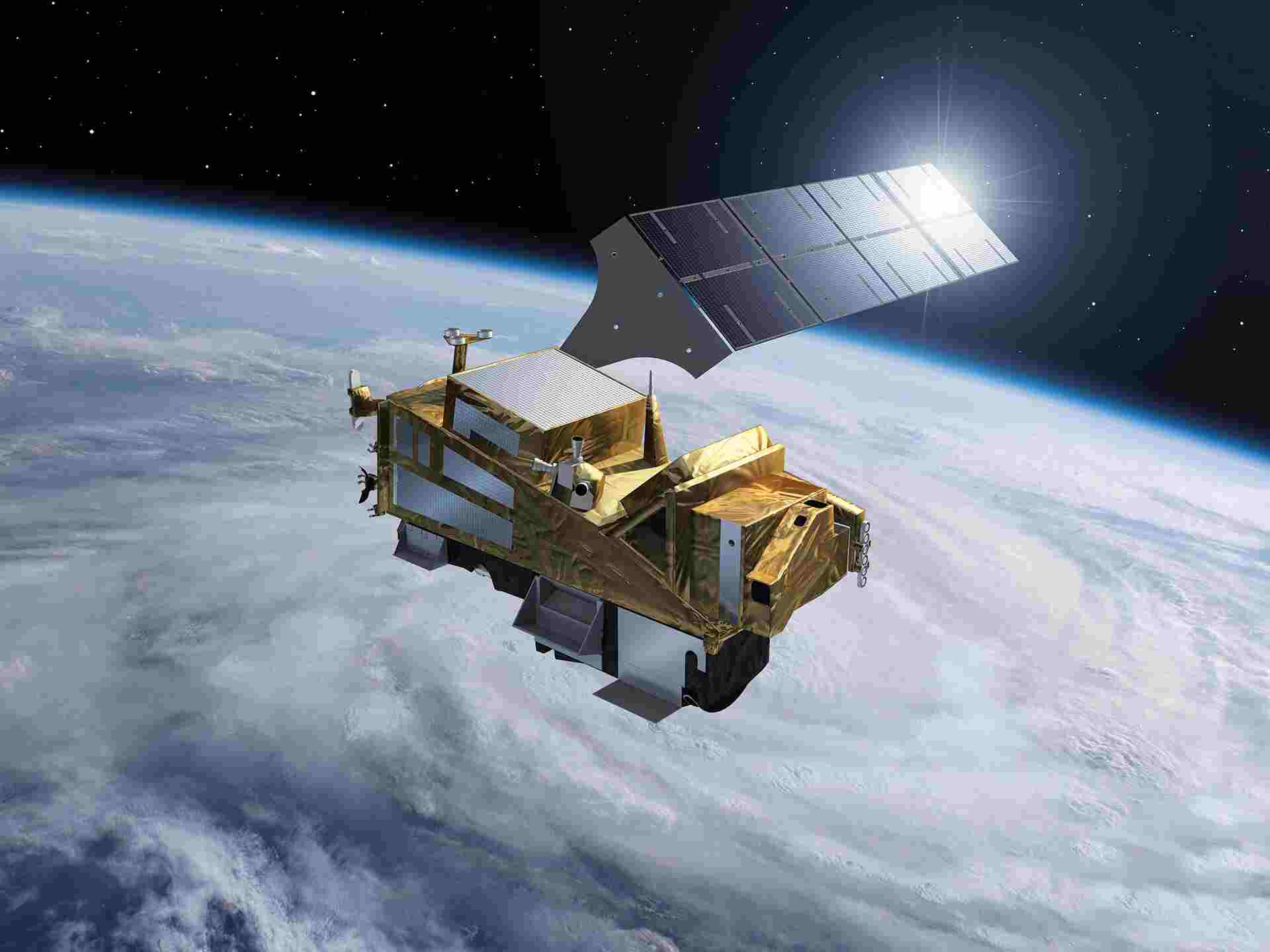
Sentinel-5 is an atmospheric monitoring instrument, part of the European Copernicus program (formerly the Global Monitoring for Environment and Security program (GMES)), that provides operational monitoring of trace gas concentrations for applications in atmospheric chemistry and climate science. It is jointly operated by the European Space Agency (ESA) and the European Commission (COM).
Quick facts
Overview
| Mission type | EO |
| Agency | ESA, EUMETSAT, COM |
| Mission status | Approved |
| Measurement domain | Atmosphere, Land |
| Measurement category | Cloud type, amount and cloud top temperature, Aerosols, Radiation budget, Albedo and reflectance, Atmospheric Humidity Fields, Ozone, Trace gases (excluding ozone) |
| Measurement detailed | Cloud top height, Cloud cover, Aerosol optical depth (column/profile), Earth surface albedo, Atmospheric specific humidity (column/profile), O3 Mole Fraction, CH4 Mole Fraction, NO2 Mole Fraction, BrO (column/profile), Volcanic ash, OClO (column/profile), CO Mole Fraction, SO2 Mole Fraction, Downward short-wave irradiance at Earth surface, Aerosol Layer Height, HCHO Mole Fraction, CHOCHO (column/profile) |
| Instruments | UVNS (Sentinel-5) |
| Instrument type | Atmospheric chemistry |
| CEOS EO Handbook | See Copernicus: Sentinel-5 summary |
Summary
Mission Capabilities
The Sentinel-5 instrument, UVNS (Ultraviolet/Visible/Near Infrared/SWIR), has been developed by Airbus Defence and Space. The instrument is a pushbroom passive spectrometer and provides monitoring of the chemical composition of the atmosphere, inclusive of air quality, climate change impact and aerosol concentration, whilst providing specific data points on trace gases such as ozone, nitrogen dioxide, sulphur dioxide, methane, formaldehyde, and carbon monoxide.
Performance Specifications
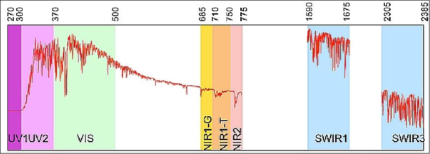
Sentinel-5 is capable of measuring across a broad spectral range from Ultraviolet (UV) to Short-wave Infrared (SWIR) (270 nm - 2400 nm). Measurements are performed in 6 spectral channels, one UV channel (270-310 nm), one UV-Visible channel (300-500 nm), three near-infrared (NIR) channels (685-710 nm, 745-755 nm, and 755-773 nm), and two SWIR channels (1590nm-1675nm, and 2305nm-2385nm). Across these channels, spectral resolution ranges from 1nm (UV) to 0.25nm (SWIR), with a swath width of 2670km and spatial resolution of 7.5km x 7.5km. The instrument has a field of view (FOV) of 108° and radiometric accuracy of 3% with the exception of the SWIR channel, which performs at 6% of the measured Earth spectral reflectance.
Space & Hardware Components
Sentinel-5 will incorporate calibration operations that track instrument responses to sun calibration, white light sources, spectral light sources, liquid emitting diodes (LEDs), aperture closure and mirrors for deep space viewing. There are several on-ground characterisation measurements that take place through the European Space Agency that include detection & electronics, spectral wavelength and response function, radiometric errors and geometric alignment. Special components, referred to as slit homogenizers, are being developed in order to mitigate radiometric errors arising from naturally occurring (across-slit) scene heterogeneity.
The Sentinel-5 instrument will be carried on EUMETSAT’s (European Organization for the Exploitation of Meteorological Satellites) second generation polar system, METOP-SG.
Copernicus: Sentinel-5
Atmospheric Monitoring Mission in LEO
Spacecraft Launch Sensor Complement References
Sentinel-5 is an atmospheric monitoring mission within the European Copernicus program, formerly the GMES (Global Monitoring for Environment and Security) program, jointly implemented by ESA and the EC (European Commission). The main objective of the mission is the operational monitoring of trace gas concentrations for atmospheric chemistry and climate applications. It will provide accurate measurements of key atmospheric constituents such as ozone, nitrogen dioxide, sulphur dioxide, carbon monoxide, methane, formaldehyde, and aerosol properties. 1) 2)
Copernicus is the new name of the former GMES program 3)
Copernicus is the new name of the European Commission's Earth Observation Program, previously known as GMES (Global Monitoring for Environment and Security). The new name was announced on December 11, 2012, by EC (European Commission) Vice-President Antonio Tajani during the Competitiveness Council.
In the words of Antonio Tajani: "By changing the name from GMES to Copernicus, we are paying homage to a great European scientist and observer: Nicolaus Copernicus (1473-1543). As he was the catalyst in the 16th century to better understand our world, so the European Earth Observation Program gives us a thorough understanding of our changing planet, enabling concrete actions to improve the quality of life of the citizens. Copernicus has now reached maturity as a program and all its services will enter soon into the operational phase. Thanks to greater data availability user take-up will increase, thus contributing to that growth that we so dearly need today."
The space segment will be implemented as an imaging spectrometer to be flown on EUMETSAT's MetOp -SG (Second Generation) satellites. From a sun-synchronous LEO orbit, Sentinel-5 measurements will complement the Sentinel-4 GEO data over Europe and provide a daily global coverage at an unprecedented spatial resolution of 7 km x 7 km at nadir. 4)
Spacecraft
The Sentinel-5 mission is a payload, consisting of a single instrument named UVNS; it will be hosted as a CFI (Customer Furnished Item) on a post-EPS (MetOp) spacecraft, i.e. MetOp-SG-A1, and will be operated by EUMETSAT. 5) In November 2012, the EUMETSAT Council successfully concluded the approval process for the EPS-SG (EUMETSAT Polar System Second Generation) Preparatory Program with all 26 Member States having now firmly committed themselves. 6) 7)
A two-satellite architecture has been selected for MetOp-SG by ESA and EUMETSAT, namely MetOp-SG A and B, flying in the same sun-synchronous orbit. Unlike the current MetOp system of identical satellites operating in a relay, the MetOp-SG system envisages a pair of different satellites, each carrying a different but complementary suite of instruments. This will comprise a mix of instruments offering data continuity with improved performance and new instruments to meet the evolving demands of the meteorological community.
Altogether, the new MetOp-SG system concept features six satellites; the launch of the first one is planned for 2021. The overall system lifetime is 21 years, with each satellite designed to exceed an eight and a half year lifetime. - On March 28, 2014, ESA signed a contract with Airbus Defence and Space in Ottobrunn, Germany for the Sentinel-5 instrument of Europe's Copernicus program. 8)
Mission | MetOp-SG-A | MetOp-SG-B |
Orbit, altitude | SSO, 817 km | SSO, 817 km |
S/C mass | ~3000 kg | ~2400 kg |
Lifetime | 8.5 years | 8.5 years |
|
|
|
Sensor complement | 8 instruments | 7 instruments |
| METimage (DLR) | MWI (Microwave Imaging Radiometer), (ESA) |
| MWS (Microwave Sounder) | ICI (Ice Cloud Imager), (ESA) |
| IASI-NG (Infrared Atmospheric Sounder Interferometer-Next Generation), (CNES) | SCA (Scatterometer), (ESA) |
| RO (Radio Occultation), (ESA) | RO (Radio Occultation), (ESA) |
| 3MI (Multi-view Multi-channel Multi-polarization Imager), (ESA) | Argos-4 (Data Collection Service) (NOAA/CNES) |
| Radiation Energy Radiometer (NOAA) | Search and Rescue (COSPAS-SARSAT) |
| Sentinel-5/UVNS (ESA/Copernicus) | Space Environment Monitor (NOAA) |
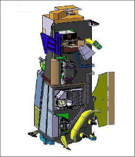
The main characteristics of the MetOp-SG A satellite, hosting the SENTINEL-5 payload instrument, are presented in Table 2. 10)
Spacecraft bus | AstroBus L 250 M from Airbus Defence and Space |
Attitude control | - Nominal mode: yaw steering - gyroless |
Power | 3.2 kW (EOL) |
Data storage capacity | 600 Gbit (sized for 1.5 orbits) |
RF communications links | - Ka-band downlink: 781 Mbit/s (2 channels) |
Launch mass | 4065 kg (+ 135 kg launch adaptor) |
Design life | 7.5 years |
Launch
Orbit: Sun-synchronous orbit, altitude of ~835 km, inclination = 98.5º, LTDN (Local Time on Descending Node) = 9:30 hours. The orbital cycle is 29 days (14 orbits per day, 412 orbits per cycle). The orbit cycle is the time taken for the satellite to return over the same geographical point on the ground with the same viewing geometry.
Mission Status
Under contract of ESA (European Space Agency), the Sentinel-5 core team is composed of Airbus in Germany, France and The Netherlands and TNO (Ref. 12).
The team is responsible for the design, development, assembly, integration, test, verification and calibration of the Sentinel-5 instrument. The satellites will be operated by EUMETSAT.
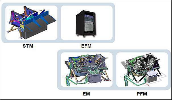
• 2017: Two instrument engineering models are currently being built: the STM (Structural-Thermal Model) for qualification of the structure and for further use at satellite level and an EFM (Electrical Functional Model) for electrical and functional representation of the Sentinel-5 at satellite level. Both are for delivery in the first quarter of 2018. For first performance assessment, the instrument EM (including the full optical path for 2 spectral chains) is in preparation, of which the Focal Plane Subsystem is already manufactured and undergoes testing throughout the year of 2017. The delivery of the PFM (Proto-Flight Model) for integration onto the satellite is expected by 2019.
• In 2014, the SRR (Systems Requirement Review) was successfully completed, followed by the accomplishment of the PDR (Preliminary Design Review) in December 2015. In parallel more than 20 subcontractors have been selected to complement the team. All subcontractors passed their PDRs and the firsts have entered the CDR process.
Sensor Complement
UVNS (Ultra-Violet /Visible/Near Infrared/SWIR) Spectrometer
The MetOp-SG A satellite(s) will carry the Sentinel-5 instrument as the Sentinel-5 mission as part of the EU's Copernicus Program. The development of the SENTINEL-5 instrument is done by Airbus Defence & Space, Ottobrunn, under contract with ESA. Many European industries have contributed to the subsystems. 11) 12) 13)
The mission goal is to monitor the composition of the Earth's atmosphere by measuring the concentration of trace gases in the atmosphere such as ozone, nitrogen dioxide, sulphur dioxide, methane, formaldehyde and carbon monoxide. Air quality will be monitored on a daily basis as well as long term to assess climate impact and change.
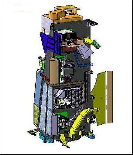
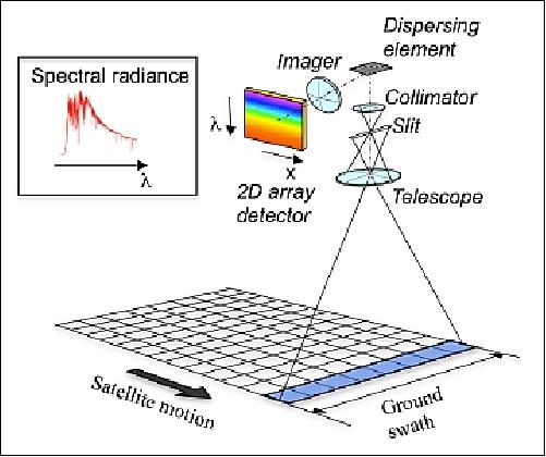
Instrument design: The Sentinel-5 instrument is a pushbroom passive spectrometer covering the broad spectral range from UV (270 nm) to SWIR (2400nm). Measurements are performed in 6 spectral channels, namely UV1 (270-310 nm), UV2VIS (300-500 nm), NIR1 (685-710 nm), NIR2a (745-755 nm) NIR2 (755-773 nm), SWIR-1 (1590-1675 nm) and SWIR-3 (2305-2385 nm), at a varying spectral resolution of 1 nm in the UV1 to 0.25 nm in the SWIR channels. From the Metop-SG sun-synchronous orbital height of 817 km, the across track FOV of the instrument extends for 108º corresponding to a swath of 2670 km on the ground, so that the entire planet is covered daily.
The main characteristics of SENTINEL-5 UVNS instrument are:
- Type: passive grating imaging spectrometer
- Configuration: Pushbroom staring (non-scanning) in nadir viewing
- Swath width: 2 670 km
- Spatial sampling: 50 x 50 km2 (UV1), 7.5 x 7.5 km2 (all other channels)
- Spectral: 5 spectrometers (1 in UV1, 1 in UV2VIS, 1 in NIR, 2 in SWIR)
- Radiometric accuracy (absolute): 3%, 6%(SWIR) of the measured earth spectral reflectance.
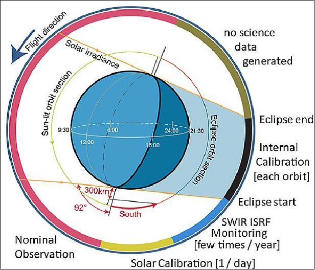
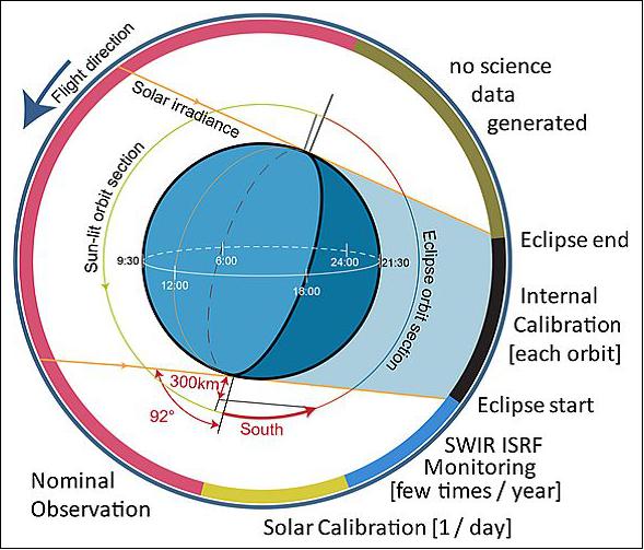
Observation is performed over the complete sunlit (with respect to the subsatellite point) part of the orbit while the instrument calibrations are done during the dark part of the orbit. The expected instrument operation is shown schematically in Figure 6.
Airbus Defence and Space is the prime contractor for the design, development, assembly, integration, test and verification of the Sentinel-5/UVNS instrument, which is a customer furnished item for the MetOp-SG-A platforms. 14)
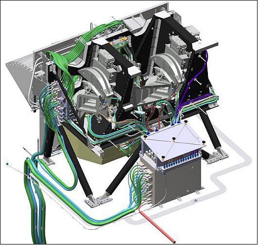
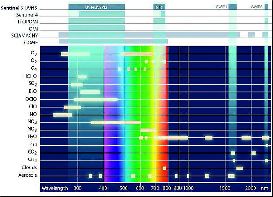
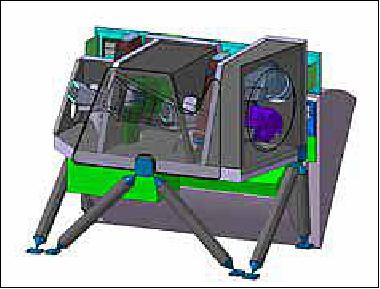
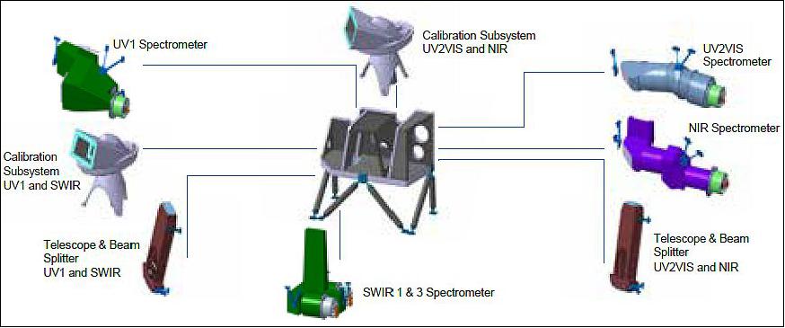
Figure 2 shows a drawing of the Sentinel-5 Optical Module, whereas Figure 3 provides an overview of the covered bands, as well as, the respective atmospheric constituents for the given bands.
Customer | ESA (European Space Agency) |
Mission objectives | Continuous measurement of the chemical composition of the atmosphere, monitoring of air quality, climate change impact, concentration of aerosols as part of the Copernicus program |
Spectral ranges | Ultraviolet 1: 270 to 310 nm NIR2: 750 to 773 nm |
Spectral resolution | 1 nm and 0.25 nm depending on the spectral range |
Swath width | 2,670 km |
Spatial resolution | 7.5 km x 7.5 km |
Service life | > 7 years |
Optical module components | • Telescope & beam splitter assembly |
Instrument mass, size | 292.5 kg, 1.0 x 1.6 x 1.2 m |
Power | 270 W nominal power consumption |
Data rate | 25 Mbit/s (max) and a maximum total data volume per orbit of 77.7 Gbit |
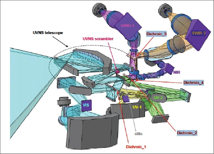
System Concept and Architecture: The instrument modular architecture consists of five spectral chains subdivided behind two co-aligned telescopes, TSBOA (Telescope, Scrambler and Beam-splitter Optical Assembly) US for UV1 and SWIR1&3 spectral bands, and TSBOA VN for UV2VIS and NIR spectral bands, respectively. The single spectrometers are individually optimized for spectral and radiometric requirements.
Key features of the UVNS
Modular architecture allowing for parallel subsystems development and flexible industrial procurement and integration.
• The single spectrometers are individually optimized for spectral and radiometric requirements. Innovative technologies for the polarization scrambler and slit homogenizer devices allow measurements with high accuracy independent of the polarization and heterogeneity of the observed image.
• The CCD detectors for the UVN channels and the MCT detectors for the SWIR channels together with the front end and detection support electronics form an integrated system for all the spectrometers.
• The calibration subsystem allows calibration with high absolute accuracy using sunlight and on-board illumination sources every orbit.
• A CFRP (Carbon Fiber Reinforced Polymer) main structure ensures mechanical and thermal stability which is required by the single spectrometers under changing loads during orbit and over the operational life of the instrument.
• The thermal control system provides passive cooling to ensure that temperature conditions are adapted to the different requirements of the instrument modules. The temperature variation is stabilized better than 1oK during one orbit.
• The instrument control subsystem performs on-board data processing and forms the functional interface to the satellite.
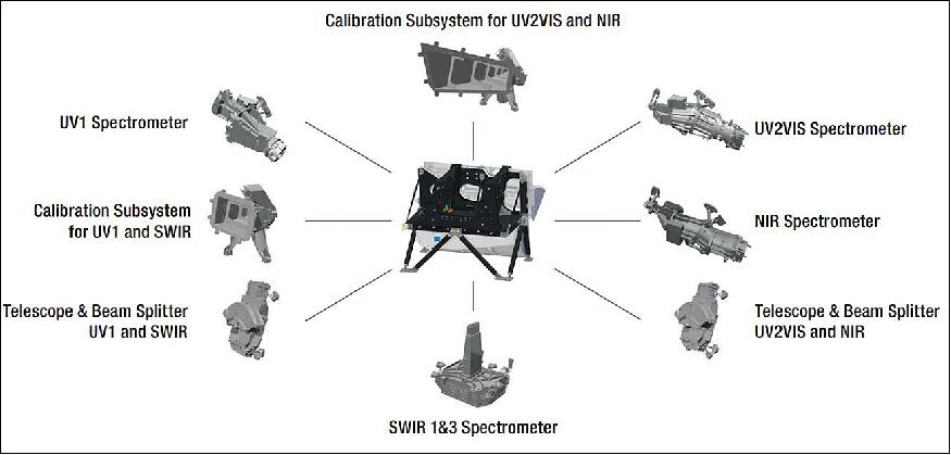
In nominal observation mode the injection mechanisms provide free access to the Earth FOV which is accepted by the 2-mirror reflective telescopes. Within each of the telescopes optical path, there is a polarization scrambler with the goal to mix the incoming polarized light and therefore reduce the instrument's sensitivity to the polarization status of the different Earth scenes. After the telescopes, the converging light path is split into the spectral bands via dichroic beam-splitters and is imaged upon the slits for the different spectral channels. For the VN channel (UV2VIS and NIR) this dichroic beam-splitter is placed after the telescope slit, whereas for the US telescope the light is split via dichroic before the slits, hence featuring two different slits assemblies (one for UV1 and other for the SWIR1&3 bands).
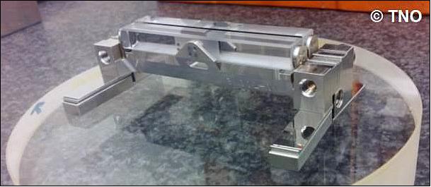
The Sentinel-5/UVNS instrument features a special type of slit, called slit homogenizer. This slit, is a reflective tunnel elongated along the direction of the light path, i.e., a three dimensional slit. Multiple reflections during the passage of this device scramble the across-slit spatial information, making the instrument insensitive to a varying illumination in this direction (as for instance in case of sea-land transition), and therefore avoiding spectral errors in the geophysical retrievals by deformation of the ISRF (Instrument Spectral Response Function).
Each one of the 5 spectral bands is analyzed in a dispersive spectrometer optics after which the spectrum is detected together with spatial across track information on a detector array. For optimum signal quality the digitizing electronics [Fees (Front End Electronics)] are close to the detectors (and therefore close to part of the instrument optics module), while other electronic units are inside the platform. The Detection Support Electronics provides control, power and timing to the FEEs while the ICS is controlling the instrument, receives the science data and performs the image processing.
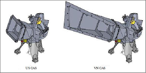
For in-orbit calibration purposes the Sentinel-5 instrument features a CAS (Calibration Assembly Subsystem), which injects different calibration signals via an actuated injection wheel with ports. Located at the entrance pupil of the telescopes this allows a full optical path calibration of the instruments. For absolute radiometric calibration the CAS provides a "sun via diffuser" signal. A reference diffuser allows monitoring the nominal diffuser for potential degradation. Other signals from the internal broadband WLS (White-Light-Source), or SLS (Spectral Line Sources), are used for relative spectral calibration and the characterization of the spectral resolution. Last elements of the on-board calibration are LEDs in each of the spectrometers for diagnostic detector linearity. The CAS is implemented in two independent units, one for each telescope.
The thermal stability of the detectors, spectrometers and calibration system is very importance to reach the performances required for the mission. The instrument thermal control is based on separate passive radiative coolers providing margin for temperature stabilization with heaters:
• UVN optics and FEEs @ 293 K (simplified optics alignment and electronics operational range)
• UVN detectors and SWIR optics @ 225 K and 200 K, respectively (avoid detector RTS effects and reduce thermal optics background)
• SWIR detectors @140 K (for dark noise reduction).
All FPAs (Focal Plane Arrays) and FEEs are arranged in nearly one plane next to the radiators allowing for effective thermal coupling and mass optimized thermal system. High mechanical stability of the optomechanical system is required to ensure the optical quality along one orbit, especially to fulfil co-registration needs and to maintain the ISRF. The externally changing thermal environment during one orbit is actively compensated by a system of heaters controlling the IOM structure and optical subsystems, keeping them constantly within a narrow temperature band.
The CFRP structure integrates all components of the IOM (Instrument Optical Module) in a compact volume with high stiffness, being this one mounted to the platform panel via bipods. All optical modules TSBOAs, UV1, UV2VIS, NIR and SWIR spectrometer assemblies and the calibration system are assembled on the boxlike structure providing enough rigidity and stability and assuring the tolerances and stabilities required for optical performance and co-registration. The optical paths are oriented such that the detectors and FEEs are located close to the radiators to avoid thermal losses and mass of the thermal links towards the radiators which are integral part of the optics module.
A comprehensive contamination avoiding design is implemented in Sentinel-5 in order to protect the cold optics and FPAs from molecular and particulate contamination during on-ground and in-orbit operations. Those measures go far beyond instrument design optimizations to use non-outgassing material or extensive bake-out of other materials. In addition, proven (e.g. on OMI) instrument operational measures are implemented, such as keeping the instrument warm during launch and during the early orbit period. This avoids any contamination during this most critical period and guarantees to stay within the end of life contamination allocation of optical throughput degradation. Last but not least, a contingency for end of life transmission degradation is integrated in the performance budget for highest system robustness.
FPAs (Focal Plane Assemblies): The detection of the UVN (UV1, UV2VIS & NIR) spectral range is covered by three identical, customized split frame transfer silicon CCDs of Teledyne e2v, each having a dedicated coating to optimize the spectral detection efficiency within its spectral chain. The detectors image is transferred in spectral direction. Their pixel pitch is 20 µm times 30 µm and they provide 1404 columns by 1350 lines.
On the other hand side, Sofradir NGP (Next Generation Panchromatic) detectors are used in the SWIR bands. The detectors are formed by HgCdTe retina with cut-off around 2.5 µm, hybridized on CMOS read-out integrated circuits. The detector features 1024 rows of 1024 pixels with a pixel size of 15 µm x 15 µm. CMOS detectors are particularly interesting since they allow smearing free detection. Good exposure control and low power dissipation make them interesting for space applications.
Instrument in-flight calibration and operations: Sentinel-5 incorporates calibration facilities to account for any deviation of the instrument response throughout its operational lifetime: sun calibration, white light sources, spectral light sources, LEDs, aperture closure for dark calibration and mirror for deep space viewing. These capabilities are implemented in the instrument's CAS (Calibration System) units as depicted in Figure 5. There is one calibration subsystem for each telescope providing adequate stimuli at the entrance pupil of each telescope.
The CAS units are composed of a rotating wheel that can be commanded to switch the input provided to the instrument telescope between earth port, sun diffuser, laser or lamp diffuser, deep space or dark/closed positions.
In normal operation, Earth observation occurs for the orbit interval where the sun-zenith angle at the observed Earth sample is lower than 92°. Once this is crossed, the sun irradiance and the remaining characterization and calibration measurements described above can be performed. The expected instrument operation is shown schematically in Figure .
Development Plan: The development plan of the Sentinel-5 was elaborated in accordance with specific satellite and verification/qualification needs. It comprises of four different models covering the respective different verification steps for the different domains. Those are described below:
1) STM (Structural-Thermal Model)
- Instrument structure and S/S mass dummies
- Structure qualification
- Thermal model correlation
- µvibs (microvibration) assessment
2) EFM (Electrical Functional Model)
- Simulated instrument to platform interfaces
- Simulated ICS functions
- Support procedures development
3) EM (Engineering Model)
- Including 2 telescopes, UV2VIS and SWIR-3 channels and 1 CAS
- Optical alignment dry run
- Performance verification & calibration dry run
4) PFM & FMs (Proto-Flight and Flight-Models)
- Fully verified and calibrated flight models.
Instrument Performance
As a result of Sentinel-5 mission targets, the instrument must meet a number of stringent performance requirements. Among them most driving are co-registration, the knowledge of the instrument spectral response function and radiometric accuracy requirements. Sentinel-5 performance requirements are mainly applicable at L1b product level. In order to be able to meet the instrument stringent performance, an elaborate instrument on-ground characterization is required.
Parameter | Specification | |
Spatial Sampling@ Nadir | <7.5 x 7.3 (ACT x ALT) km2 (λ>300 nm) | |
Spatial Sampling@ Nadir | 108.4º | |
Spectral Range | UV1 | 270-310 nm |
Spectral Resolution | UV1 | 1 nm |
Radiometric Resolution (SNR) | UV1 @ 290 nm | >230 |
Polarization Sensitivity | UV1 | 0.005 |
System Integrated Energy (1 x 1 SSD) | UV1 | >70% |
Radiometric accuracy |
| 3% |
Technology Developments
Most Sentinel-5 components rely on flight proven technologies used for existing missions as for example OMI, or are being developed for TROPOMI or Sentinel-4. In support to the instrument early de-risking activities, several technology developments over the whole product tree have been carried out and are worth to highlight.
Polarization scrambler: The polarization scrambler uses materials and material bonding that has been developed for TROPOMI and Sentinel-4. The feature specific to Sentinel-5 is the split aperture design, which together with the tight manufacturing tolerances required a pre-development in Phase B to show the manufacturability of this component.
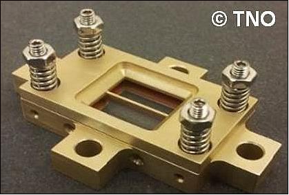
Slit homogenizer: The slit homogenizer is a key technology development with the goal to smear out any scene non-homogeneity in the along track direction that would modify the spectral response of the instrument introducing errors in the geophysical retrievals. A demonstration of manufacturability and mount stability addressing the challenging slit straightness and planarity of optical elements was successfully reached.
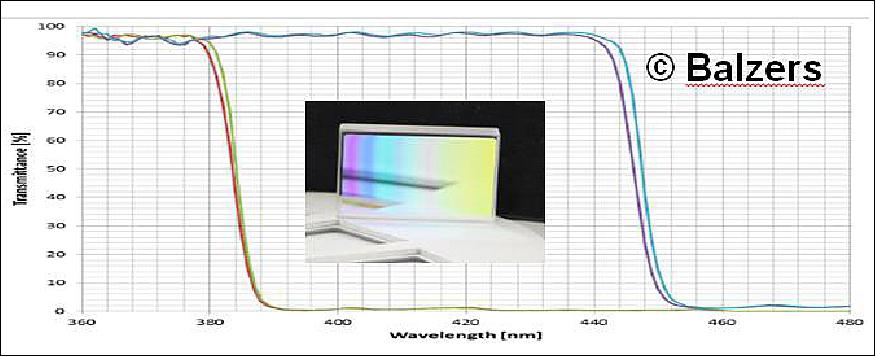
Straylight suppression graded coating: An important technology development was the straylight suppression graded coating deposited on top of the the last lens surface, directly in front of the detector for the UV1 and UV2VIS spectrographs. This coating is basically a low-pass transmission filter with a position dependent cut-off wavelength. At the position where short wavelength light passes the filter, longer wavelength in-band stray light ghosts are blocked.
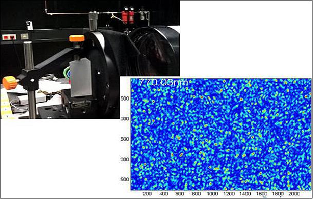
Calibration diffuser: The baselined on-board calibration concept relies on Mie scattering volume diffusers, for which a prior breadboard existed, but for the Sentinel-5 specific speckle performance, there was the need to be demonstrated, as well as the stability of the spectral BSDF (Bidirectional Scattering Distribution Function) w.r.t. irradiation.
CFRP cores and face sheets: A key aspect to verify prior to instrument procurement was the verification of the adequate performance of the CFRP panels used to support the optical subsystems and related equipment. A campaign with a Design Validation Sample was carried out, demonstrating the suitability of the CFRP cores and face sheets for the panels.
Immersed gratings: For the SWIR wavelength chains, pre-development breadboard featuring immersed gratings were built in order to verify the bonding technology and demonstrate the required performance, especially the straylight.
Free-form mirrors and lenses: Pre-developments on free-form mirrors and lenses were also carried out building on TROPOMI instrument heritage.
Instrument On-Ground Calibration
In order to meet the instrument stringent L1b product accuracy requirements, a comprehensive instrument on-ground characterization is required. The goal is to retrieve, with sufficient accuracy, the Calibration Key Data parameter values which will be used in the L0-1b processor.
The on-ground characterization of the instrument will be performed under flight representative conditions at the RAL facilities (UK). In Figure 16, one can see a picture of the current facility featuring the vacuum chamber.
The large 5m diameter TVC (Thermal Vacuum Chamber) is equipped with two optical windows, allowing parallel illumination of the instrument telescopes by the OGSE (Optical Ground Support Equipment) mounted in an adjacent cleanroom. It is worthwhile to note that the number of parallel measurements between the two channels is, as far as possible, maximized, so that overall duration of the C&C measurement campaign is reduced.
On-ground characterization measurements: The on-ground characterization measurements are divided into five categories addressing the five categories of instrument key-parameters as defined by ESA, i.e., detector and electronics, spectral, radiometric, geometric, and others.
Detector and electronics: For the characterization of the detection chain aspects of the instrument, mainly the instrument internal sources will be used, in particular the LEDs and the WLS (White Light Source). The LEDs are used to determine the detector chain linearity via changing the detectors integration time. In a stable environment, the LEDs prove to be a very stable source of light. The goal of this set of measurements is not only to characterize the linearity of the detectors, but also to obtain a correction curve to the level of 0.1%. Furthermore, and in order to reduce the measurement time, 2 LED's with a factor 10 difference in radiance are employed, so that the large dynamic range can be more easily covered. For the CMOS detectors (SWIR bands) this approach is not required as the exposure times can be set much shorter.
The WLS, on the other hand, will provide a mean to characterize the PRNU (Pixel Response Non-Uniformity) of the different detectors. The PRNU is caused by tolerances of the detector manufacturing process and is wavelength dependent; hence the LEDs are not adequate for this measurement. The instrument is therefore equipped with white light sources which will deliver a smooth spectrum via the spectrometer. High frequency features in the measurement will be classified as PRNU.
Spectral: On the spectral side two main parameters are to be extracted: the wavelength assigned to each pixel, and the ISRF (Instrument Spectral Response Function) of each pixel. - As for the spectral assignment, a novelty is the utilization of a tunable laser, which is an improvement compared to its predecessors such as, GOME, SCIAMACUI, OMI, GOME-2, TROPOMI, which had employed spectral emission lamps and absorbing gas-cells. This novel approach provides a quasi-continuum selection of wavelengths and an accurate determination of the dispersion curves.
Radiometric: As for the on-ground radiometric calibration, the approach is rather straightforward. A calibrated 1000 W FEL (Field Emission Lamp) from NIST will be used. This, in combination with a calibrated external diffuser (ODIFF) will provide the stimuli for an accurate radiance response at nadir. From nadir, this absolute radiance response is transferred to all other viewing angles and to the sun irradiance response using a combination of measurements with an integrating sphere and a sun simulator covering the radiance response over the complete telescopes FOV.
For the absolute irradiance response, a dedicated SUSI (Sun Simulator) will be used. This source simulates the sun in the sense that the illumination geometry is comparable to the sun but not the irradiance level (unlike commercial sun simulators, which focus on high output flux). Several reasons prevented discouraged the use of FEL source as irradiance source, being the main ones: the low UV flux of the FEL lamp, and the limited calibration validity (50 burn hours). Since the Susi is not absolutely calibrated, the irradiance calibration of the FEL is transferred using radiance measurements for both sources on nadir direction. The measurements with the Susi on the sun port will be performed for several angles such that the relative dependence on the sun incidence angle can be determined.
Finally, the instrument BSDF needs also to be determined [instrument BSDF (Bidirectional Scattering Distribution Function) is the ratio between the absolute radiance response and the absolute irradiance response of the instrument]. This ratio will be determined on the SUSI measurements for radiance and irradiance.
Geometric: This set of measurements is composed of measurements of Earth and Sun Port viewing angles, as well as the instrument spatial response function. -During the on-ground characterization, it is only foreseen to characterize and verify the clear sun FOV, i.e., the instrument response as function of SUSI angle of incidence on the diffuser for those viewing angles where the SUSI fully illuminates the diffuser. Nevertheless, there will be a limited set of measurements going beyond the field of view to check performances.
As for the Earth port, the measurements have to deliver input for both the line of sight with respect to the Instrument Alignment Cube (IAC), as well as the spatial response function. For this a field scan with a narrow field source in one direction (either along track or across track) is foreseen. The complete wavelength range is covered by using an external WLS (White Light Source).
Others: This category, for the case of Sentinel-5 covers straylight and polarization measurements. For polarization it is required to determine the first three elements of the Müller matrix. The first element of the Müller matrix is the absolute radiometric response. The second and third element will be determined relative to the first element with a scan of linear polarized light in front of the earth port.
Regarding straylight, this will be measured with a laser and with filter measurements. The laser will be coupled to the instrument via the Earth port and will result in a spot at the detector. However, due to limitations on the dynamic range filters need to be employed leading to a blur of ghosts.
Instrument Requirements
1) Geometric requirements
One of the most outstanding characteristics of the Sentinel-5 mission are manifested by an unprecedented spatial coverage and sampling. The scientific requirements demand full coverage of the entire globe with a daily revisit frequency. Figure 18 depicts the observation geometry and coverage. For a LEO mission at MetOp SG's envisaged orbit altitude of 817 km, daily coverage requires an average swath width of 2715 km (slightly varying due to the oblateness of Earth and orbit eccentricity). As can be seen from upper right panel, small gaps occur at the equator resulting in a revisit period of about two days, whereas daily revisit is reached beyond 14° latitude (see lower panel). The enormous swath width translates at instrument level into a large cross-track FOV of 108.4° (see upper left panel).
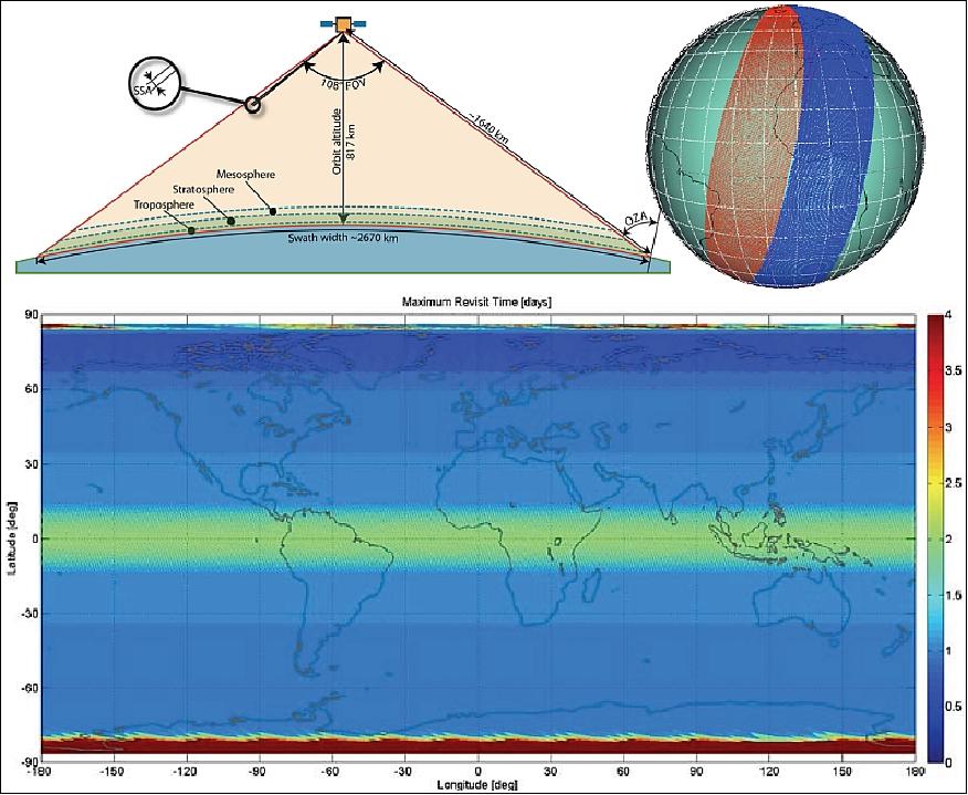
Legend to Figure 18: Upper left: Daily global coverage requires a wide swath (2715 km) and across-track field of view of 108.4°. Upper right: Swaths of two consecutive orbits, indicating small gaps at the equator. Below: Resulting revisit frequency map, showing the daily coverage within less than one day above 14° latitude.
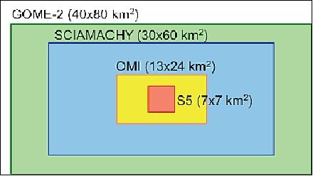
Another characteristic of Sentinel-5 is the high spatial resolution of the trace gas measurements. At nadir, the area over which all targeted species are determined, will have a maximum size of 7 km x 7 km. Figure 19 shows a comparison between the ground pixel size of Sentinel-5 and its predecessor missions GOME, SCIAMACHY, and OMI. The high spatial resolution will enable more accurate detection of emission sources and provide an increased number of cloud-free ground pixels. The ground samples will be observed under equal sampling angles, which means that the across-track SSD (Spatial Sampling Distance) will vary over the swath and reach 35 km at its edges. The along-track (ALT) component of the SSD is determined by the dwell time and remains constant at 7 km. The MetOp-SG platform will perform continuous yaw steering maneuvers over the orbit to compensate for image distortion and misregistrations induced by Earth rotation.
Some atmospheric products are inferred from simultaneous measurements in different spectral bands, which have to be acquired over identical spatial samples (or ground pixels). This results in stringent co-registration requirements, allowing for inter-band deviation of only 10% of the ground pixel size (< 700 m at nadir) and driving optical as well as mechanical designs to minimize such errors. Apart from optimizing image quality (minimize keystone errors) this involves a careful design of the polarization scrambler, which can induce coregistration errors depending on the polarization state of the measured radiance.
2) Spectral requirements
The large number of targeted atmospheric constituents can only be measured over an extremely broad spectral bandwidth, spanning from the UV (starting at 270 nm) to the SWIR spectral regions (up to 2385 nm). The simultaneously measured spectral bands are depicted in Figure 20. The spectral resolution varies from 1 nm in the UV1 (270-300 nm), used for retrieval of stratospheric O3 profiles, over 0.5-0.4 nm for the visible and NIR range, respectively, to 0.25 nm in the two SWIR bands. A spectral resolution element is sampled by 2.5-3.0 detector pixels in order to avoid spectral aliasing.
The broad and partially discontinuous spectral range dictates, that the light collected by the instrument's telescope must be spectrally split and distributed to a number of individual spectrometers. For each of them, a spectral knowledge of 1.5 pm (picometer) is demanded; the stability requirements (15 pm) call for a very robust design and an accurate on-ground calibration. The shape of the ISRF (Instrument Spectral Response Function) has to be known within 1% throughout the mission lifetime (7.5 years), which calls for an in-flight monitoring utilizing a spectral stimulus device. Technology solutions for meeting these demanding specifications are currently under investigation.
3) Radiometric requirements
The signal-to-noise (SNR) requirements are driving the instrument pupil size, and have been derived from sensitivity analyses for the retrieval of each individual molecular species. Which spectral ranges are driving the aperture size of the instrument depends on the chosen concept. A notoriously challenging region, especially in terms of straylight, is the UV2 region due to a variation of radiance levels over 3 orders of magnitude within a short spectral range (indicated in Figure 20). Special techniques, like graded filters may be necessary to cope with the enormous dynamic range. The high accuracy requirement for retrieval of NO2 columns is driving the SNR in the VIS region to 1500. In the SWIR regions, where CO, CO2, CH4 and H2O provide strong absorption signals, a known limiting factor is the readout noise of the MCT (Mercury Cadmium Telluride) CMOS detectors.
While SNR limits are in principle always achievable by increasing the pupil size (and with it size and mass) of the instrument, the demanding requirements for relative and absolute radiometric accuracy are pushing technology to the limits of feasibility. The relative spectral radiometric accuracy (RγRA) describes spurious features in the measured spectra, which propagate into the retrieval error. There are many contributors to this error, including speckles from the sun calibration diffuser, spectral straylight and polarization scrambler effects. One major contributor is also the instrument's sensitivity to the strongly varying polarization of the signal.
In the NIR region, the degree of polarization of the TOA Earth radiance can vary rapidly with wavelength from nearly 0 (in the continuum) to almost 100% (in the center of the O2 A-band). The Sentinel-5 requirements limit the polarization sensitivity of the instrument to below 0.5% in the UV, VIS and NIR, which is only achievable by utilizing a spatial pseudo-depolarizer as an optical component, which de-polarizes the light collected by the telescope.
Another contributor to spectral errors analyzed within the S5 feasibility studies are radiometric artifacts arising from the spatially heterogeneous nature of the radiance emanating from the Earth surface (due to irregular cloud cover or albedo variations within a spatial sample). The varying radiance levels across the slit (in ALT direction) result in an inhomogeneous illumination of the entrance slit, and consequently in a distortion of the ISRF (Instrument Spectral Response Function).
The upper right panel of Figure 21 depicts a simulated ISRF, which is deformed by realistic scene heterogeneity as inferred from MODIS imager data. The radiometric error resulting from the absence of knowledge in the ISRF distortions is referred to as PN (Pseudo Noise), because it behaves like random noise in the spatial direction whereas it correlates strongly with the measured signal along the spectral direction. The simulated PN in the NIR-2 for the analyzed scene is also plotted in Figure 21. Error levels of several percent are incompatible with the requirement on RγRA, which allow maximum errors of only 0.05% in the VIS and NIR bands.
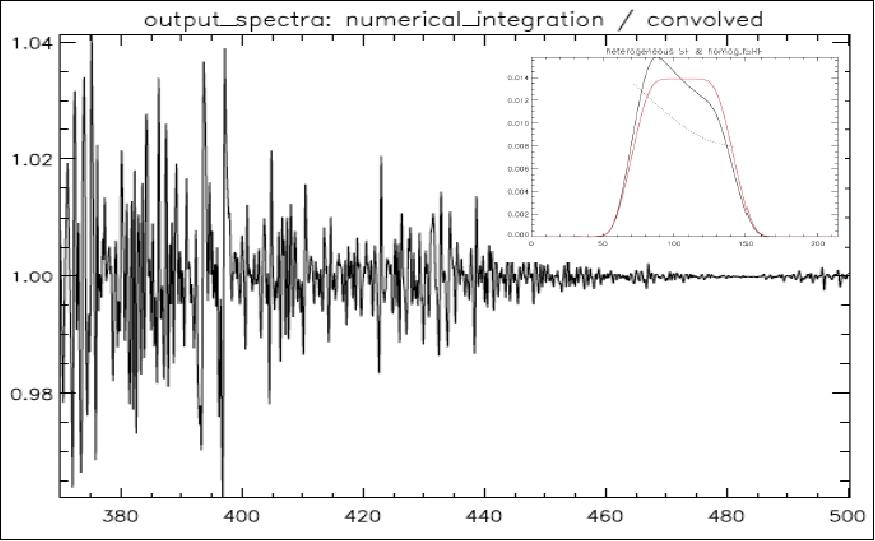
Therefore, dedicated correction techniques have to be developed. A significant part of the PN error results from a spectral shift of the ISRF barycenter, seen in Figure 21, and can largely be corrected by suitable spectral calibration techniques. However, the distortion of the ISRF shape still exceeds the 1% required for Sentinel-5 and additional measures may be necessary for PN mitigation. A prediction of the distorted ISRF is possible by means of temporally highly sampled radiance measurements, which provide sub-SSD spatial resolution in the ALT direction. The resulting possible software correction is supported by dedicated requirements for Sentinel-5, requesting so-called "small-pixel" data. Alternatively, it is possible to correct the non-uniform slit illumination by means of a slit homogenizer.
Summary of S5 instrument characteristics
• Nadir-viewing pushbroom UVNS spectrometer, 2 telescopes
• Spectral ranges between 270 and 2385 nm
• Spectral resolution 0.25 – 1.0 nm, oversampling factor 2.5 – 3
• Daily coverage at latitudes > 12º
• Spatial resolution 7.5 km @ nadir (45 km at λ < 300 nm)
• High SNR (Signal/Noise Ratio)
• Demanding requirements on radiometric accuracy, spectral calibration and spatial co-registration
Special Hardware Developments
SH (Slit Homogenizer)
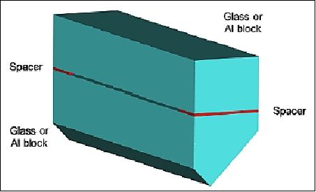
Special components, referred to as slit homogenizers, are being developed in order to mitigate radiometric errors arising from naturally occurring (across-slit) scene heterogeneity. One possible realization of a slit homogenizer, shown in Figure 22, is a three-dimensional slit, consisting of two parallel, highly reflective mirrors. The incident beam at the SH entrance (coming from the telescope) is reflected several times in ALT (across slit) direction between the mirror surfaces, which "scrambles" the spatial information in this direction. In order to maintain the ACT spatial resolution, an anamorphosis has to be introduced, focusing the ALT component of the beam from the telescope on the entrance of the SH and the perpendicular ACT component on its exit.
A perfect SH would equally distribute the radiation incident at the entrance across the exit of the device, resulting in a uniform illumination pattern at the exit. The homogenizing effect can be quantified by transfer functions, which represent the across-slit intensity distribution resulting from a Dirac-type stimulus at the entrance of the SH. For an ideal device, the transfer functions are boxcar shaped for any across-slit position of the incident beam. In reality, they deviate from this behavior due to interference between mirror reflections. The left panel of Figure 23 shows a 2D color representation of the across-slit energy distribution (vertical) as a function of the position of the stimulus at the SH entrance (horizontal). A cross section of this plot depicted in the right panel of Figure 23 illustrates the non-ideal transfer functions. Nevertheless, first results indicate that SH devices reduce PN levels by roughly an order of magnitude.
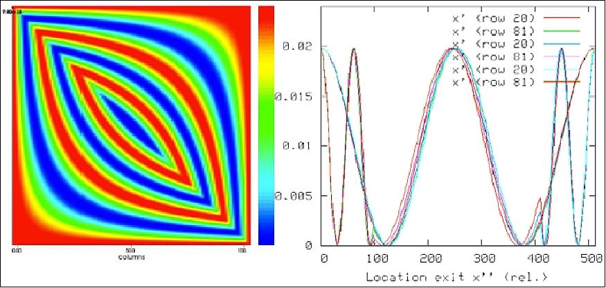
Legend to Figure 23: The 2D color plot on the left panel shows the slit exit illumination (vertical axis) for a Dirac input illumination as a function of its position across the input of the homogenizer (horizontal axis). The right panel shows a few the slit exit energy distributions, which are cross sections of the left plot. To obtain the ISRF from these illumination patterns they have to be convolved with the spectrometer and detector point spread functions.
Polarization Scrambler
The stringent requirements on polarization sensitivity and RγRA necessitate the deployment of a pseudo-depolarizer or scrambler. The most suitable type is the DBCP (Dual Babinet Compensator Pseudo-depolarizer), consisting of four wedges of birefringent material arranged in pairs (Figure 24). The wedges of a pair are bonded with crossed crystal axes, and the first pair is rotated by 45° w.r.t. the second one. Light beams passing through this device experience polarization dependent phase delays, which vary over the pupil and the resulting polarization states at the exit largely average out.
The ideal position for the scrambler would be in front of the telescope so that all optical components are illuminated with de-polarized light. However, this is impossible for the Sentinel-5 instrument, because of the large ACT FOV and the corresponding large incidence angles (up to 54°) resulting in non-acceptable spectral oscillations in the residual polarization sensitivity. The telescope mirrors placed before the scrambler will therefore contribute to the instrument's polarization sensitivity.
A known feature of DBCP scramblers is that polarized light passing through the four wedges is split into four beams due to birefringence. This effect is a direct consequence of the depolarization and cannot be avoided. Due to the geometry of the device, the four beams are arranged in a parallelogram, resulting in a "diamond spot pattern" at the detector. The stronger the de-polarization power of the DBCP, the greater is the separation of the four spots. As a consequence of the beam separation, a detector element traced through the instrument is imaged four-fold onto the Earth surface, which effectively reduces the spatial resolution. The latter is described in terms of the integrated (or ensquared) energy, representing the fraction of photons originating from a given ground pixel. The requirements for polarization sensitivity and integrated energy are in conflict, one calling for high and the other for low depolarization power, and a balance between them has to be found by careful design.
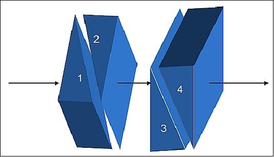
The energy distribution between the four spots of a classical DBCP scrambler's diamond pattern depends on the polarization state of the incoming light, which varies strongly not only with the viewing geometry, but also with wavelength. This gives rise to a spectrally dependent effective pointing, inducing a co-registration error between spatial samples probed at different wavelength. In order to comply with the stringent co-registration specifications for single- (10% of SSD, 700 m at nadir) and multi-band (20% of SSD) retrievals, modifications of the DBCP scrambler design are being developed by the Sentinel-5 industrial primes to reduce polarization independent pointing.
Parameter / Instrument | MERIS | OMI | Sentinel-4 | Sentinel-5 |
Target measurements | Land, Ocean, Atmosphere | Ozone | Atmosphere | Atmosphere |
Platform | Envisat | Aura | MTG-S | MetOp-SG |
Overview | Medium resolution pushbroom, 5 cameras in fan shape | High resolution pushbroom | High resolution, E-W scan mirror | High resolution pushbroom |
Pupil | Close to rectangular 40 mm x 20 mm | Rectangular 7.6 mm x 5.6 mm | Circular 95 mm diameter | Small |
FOV | 68.5º (total), 14º (per camera) | 115º | 4.2º | > 108.4º |
Scrambler | MERIS | Dual Babinet | Variant of Dual Babinet | Not yet defined |
Scrambler position | Before instrument | Inside telescope | Inside telescope | Inside telescope |
Scrambler illumination | Collimated | Weakly converging, chief ray at ±15º | Converging F/2.7, normal chief ray | Not yet defined |
Gratings
Diffraction gratings are the preferred dispersing components for wide-swath push-broom spectrometers and for atmospheric applications requiring a spectral resolution around 0.5 nm. However, they are also a significant source of straylight and polarization sensitivity. Therefore special care has to be taken regarding the choice of grating technology for each individual spectral band. In the UV, VIS and NIR, a number of solutions are available, including convex blazed holographic, binary transmission, Echelle and prism gratings. For the two SWIR regions, the resolution of 0.25 nm in combination with the stringent limitations on volume and mass make the use of immersed gratings mandatory. These devices are reflective gratings formed on a prism, where the incident light is dispersed inside the substrate material.
Refraction at the exit surface further increases the angular dispersion, which allows reaching high spectral resolution with a much smaller grating than in a conventional setup. As a rule of thumb, the reduction in volume resulting from using an immersed grating w.r.t. a conventional one, is on the order of n3, with n being the refractive index of the substrate material. This advantage is essential for Sentinel-5 and its stringent envelope limits (1.2 m x 1.1 m x 1.0 m). Among possible substrate materials with high refractive index in the SWIR, silicon (n=3.4) offers the most mature technology and is the baseline for the Sentinel-5 Precursor mission.
Detectors
The final key component encountered by the light is the focal plane assembly housing the detector. The broad targeted spectral range requires individual technology solutions for each spectrometer. In the UV, VIS and NIR regions, frame transfer CCDs (Charge-Coupled Devices) based on silicon are usually the technology of choice. Scientific CCDs feature high quantum efficiency and full well capacity, and good linearity over a wide dynamic range. The technology is mature and available in a variety of formats, which can be shaped according to the needs. From the principle of the pushbroom spectrometer concept, it is clear that detectors with fast readout capability are required, to maximize the detection time and avoiding gaps in spatial coverage. In case of CCD detectors, this is achieved by a frame transfer, in which the image acquired over the dwell time is transferred into a storage region.
From the storage region the image is successively read out while the next image is already acquired in the exposure region. The readout can be performed both in spectral (across-slit) and spatial (along-slit) direction, which in turn has implications on the video chain layout. Since the detector pixels are continuously illuminated during the charge transfer, the frame transfer has the disadvantage to create a smear effect on the signal, which needs to be corrected.
Since silicon is not responsive for wavelengths beyond 1000 nm, alternative detection media have to be considered in the SWIR spectral regions, like InGaAs or HgCdTe (MCT). MCT CMOS devices are a viable solution due to their high industrial maturity. While U.S. companies have accumulated a considerable advance in this technology, European detectors are only available in relatively small formats (256 x 1024 pixels) and with large pixel pitch (30 µm), which imposes constraints on the optical design. ESA has initiated pre-development activities with European companies on new generation SWIR detectors offering formats of 1024 x 1024 pixels with pixel sizes < 20 µm. Although these pre-developments are not yet completed, they are currently baselined as the detector solution for the Sentinel-5 mission.
UV2VIS Spectrometer Module of UVNS
SODERN (Societe Anonyme d'Etudes et Realisations Nucleaires — French instrument company, Limeil-Brévannes, France) is developing the optics of the UV2VIS spectrometer (UV2VIS SO). It is the optical part of the UV2VIS spectrometer, linking the slit – attached to the telescope – to the CCD array. It operates from 300 to 500 nm. The Sodern instrumental participation in Sentinel programs at a glance is depicted Table 6. 17)
Applications | Instrument names | Sodern participation |
Supporting global land and ocean monitoring services, in particular: sea/land color data on the third Sentinel-3 instrument | OLCI (Ocean and Land Color Imager) on Sentinel-3 | COSA (Camera Optical Sub-Assemblies) and |
Supporting European atmospheric composition and air quality monitoring services. The Sentinel-4 mission is carried on the MTG satellite. | UVN (UV-VIS-NIR) on Sentinel-4 | Polarization scrambler |
Supporting European atmospheric composition and air quality monitoring services. The Sentinel-5 mission is carried on MetOp-SG satellite. | UVNS (UV-VIS-NIR-SWIR) on Sentinel-5 | UV2VIS (Ultraviolet 2 Visible) Spectro-Optic (SO) |
Note: As of 2016, UV2VIS SO is in its PDR (Preliminary Design Review) phase. The outcome of the study, using the competence and know-how on optical modules is well on its way and continues through completion and delivery of the EQM (Engineering and Qualification Model) in late 2017.
The UV2VIS Spectrometer optics (SO) is one of the seven optical modules of the UVNS currently under development. In contrast with OLCI optomechanical design that benefits of the close heritage of MERIS, UV2VIS Spectro-Optic (SO) presents a completely new approach and challenge in direct response to Airbus DS needs. This includes extensive design, modelling and analysis of optical diffractive and refractive optical elements and optomechanical mounting and adjusting with kinematic configurations.
How it works: After the fore optics plus scrambler, the working principle is that the collimator brings the light from the slit to the grating with its pupil on the grating or disperser surface. Then the grating disperses the incoming light. Finally the camera re-images the light onto a two-dimensional CCD array. The classical block diagram of instruments is provided in Figure 25 showing Sodern project's scope. The width of the UVNS total spectral range to be covered and the differencing requirements and technologies necessitate an implementation using a few separate dispersive elements not shown.
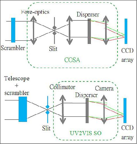
An overview of COSA (Camera Optical Sub-Assemblies) is shown Figure 26 and Figure 27. Eleven flights models were already delivered with launch of firsts models last February.
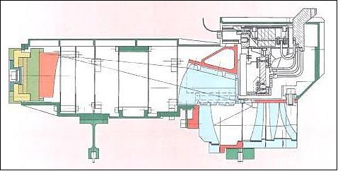
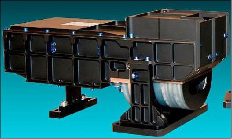
The major features relevant for Sodern activities are provided in Table 7.
Features (in size) | MERIS and OLCI COSA | UV2VIS SO |
Prime contractor | TAS-F (Cannes) | Airbus DS (Munich) |
Heritage | Same design as MERIS (on Envisat), Completing its development phase(1st launch in February 2016) | New concept |
Wavelength range | 390 – 1040 nm | UV2 (300 – 370) nm |
Disperser | Concave grating (132 grooves/mm) | Transmission prism-grating (1500 grooves/mm) |
Lenses | Original catadioptric design with Silica half-components | Silica and CaF2 lenses |
Optomechanical design | Silica barrels, INVAR baseplate and titanium housing | Titanium barrels and structure |
Focal plane size | 17 x 13 mm2 | 40 x 28 mm2 |
Mass | 4 kg | 14 kg |
UV2VIS SO (Spectro Optic) Overview
The specification allocates a certain volume to the UV2VIS SO and also sets the position of the input and output ports. It is adapted to a refractive design with mirrors present inside the collimator only to redirect the light from the input port (the slit) to the output port (the detector). Due to the spectral range (300 nm – 500 nm) there are only two optical materials available: fused silica and calcium fluoride (CaF2). These two optical materials are used for chromatic correction.
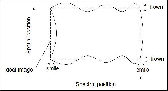
Correction for the distortions of the final image, that are usually called "frown" or spatial misregistration and "smile" or spectral misregistration, is mandatory (Figure 28). Frown is a variation in position of the spectra associated with each point on ground, introducing errors in spatial registration of spectral data read from parallel detector columns. The adopted optical design consists of a collimator including cylindrical lenses and a camera including a "knee" to correct the lateral chromaticism and to meet the frown requirement.
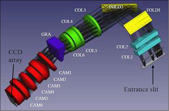
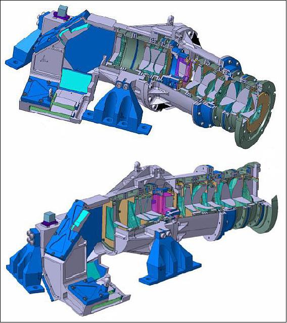
A 3D view of the optics is shown on Figure 29 . It includes; a collimator group made of two lenses with cylindrical surfaces (light blue) two folding mirrors (yellow), and four lenses (green), a monolithic prism (dark blue) with the grooves etched on the exit surface and finally the camera group (red) made of six lenses. The largest refractive elements are on the order of 75 mm clear aperture diameter. The lenses surfaces are either spherical or aspherical. Within the housing are contained LED sources for calibration purposes. Indeed outward-projected sources are used to verify photo response non-uniformity pattern of the detector.
A spectral variable transmission coating or inverse filter is implemented on one of the collimator cylindrical lens in order to optimize the instrument spectral response; including optical transmission, spectrometer diffraction grating efficiency and CCD responsivity, for radiometric performances.
UV2VIS Spectro-Optic mounting attributes: The quality of optical systems depends not only on the quality of the optical components, but also strongly on the quality of the assembly and mounting of the different optical components.
Driving requirements for the mounting hardware, lens housing and fasteners are: low mass to support tight overall mass budget, high stiffness to meet minimum launch frequency, adequate strength to ensure that the complete system can withstand extreme environmental conditions, high dimensional stability to maintain optical alignment, sufficient thermal conductivity to minimize thermal gradients during operation which cause thermal distortions. Titanium turned out to be the best choice dictated mainly by thermo-mechanical considerations and cost-effective compromise. Indeed the titanium allows manufacturing of lightweight complex shape, no surface preparation is needed minimizing cleaning and contamination risk and it offers an intermediate thermal expansion matched to silica and CaF2 substrates.
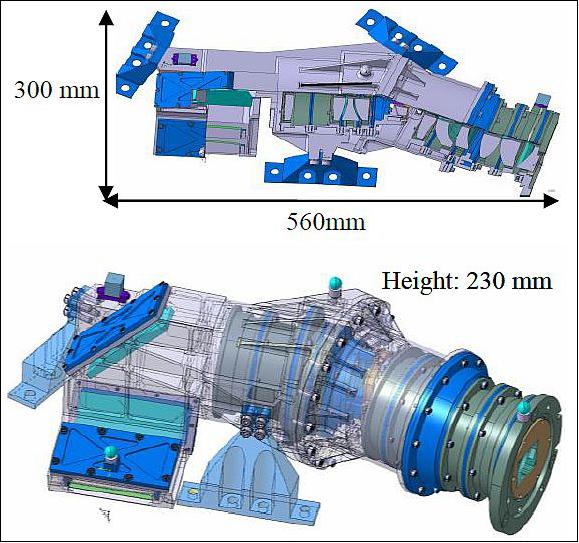
In a structural point of view, the Spectro-Optic consists in a main body supported by three kinematics bi-pods as shown Figure 30.
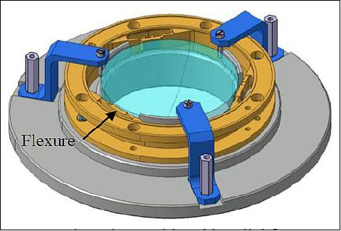
Each camera lens element is mounted as a singlet. Lens glass substrate demands a unique mount for space launch. The challenge is to design barrels that presents enough strength and stiffness to hold the lens in an accurate position to face vibrations, or shock loads, but that has simultaneously enough flexibility to filter the thermal expansion differential between the titanium and the glass, and externally induced deformations in order to mitigate impact on WFE (Wave Front Error) and birefringence. To this aim, it is necessary to implement three machined flexures inside each barrel as depicted Figure 31 with one degree of freedom per flexure at each mounting point.
With such a concept an isostatic mount with epoxy bonding is achieved. Nevertheless the flexures will only compensate the radial/global thermal load and stress could be induced through the glue (epoxy glue presents a high elastic modulus in the range of 1 GPa) if the CTE mismatch is too large and cause glass breakage. An efficient solution is in this case to insert a pad whose CTE is closer to the one of the glass between the optics and the flexure. In this way the most fragile element (i.e. the glass) is protected.
The proposed bonding technology influences the accuracy of the positioned component as well as the long-term and temperature stability of the assembly. Therefore the bonding and the pad dimension is optimized for each optical element.
This adopted lens mount design has however a direct consequence on the minimum lens edge thickness of about a few millimeters. Moreover for this application involving tight outgassing specification, due to the 300 nm wavelength, the joining technology with organic bonding remains critical, what requires bake-out prior to assembly the lens plus barrel into its final position.
UV2VIS Spectro Optic thermal design overview: This includes all hardware used for the passive and active thermal regulation; heaters and thermistors for the thermal regulation in operation mode and heaters and thermostats used to maintain the SO at non-operational temperatures. Thermal modelling and investigations aim at making Spectro Optic insensitive to temperature influences from the environment or interface temperature fluctuations that occur during one orbit. There are stringent requirements on optical performances and stability with tolerances as shown Table 8 therefore appropriate thermal regulation is needed.
dX & dY | 0.25 µm |
dZ (focus) | 1 µm |
dα & dβ | 5 µrad |
ΔT change over one orbit | 0.5 K |
ΔT over the life time | 4 K |
The SO operates at room temperature and is decoupled thermally from the baseplate with the low conduction bipods. Low external surface emissivity ~0.17 is chosen so that radiative interfaces are expected to have relatively small effects. The cold detector module is connected to the last camera lens mount with a distance of ~6 mm. And besides this additional load being cantilevered and causing bending of the main SO housing, the boundary module temperature complicates the thermal architecture and sizing of the heaters.
Thermal effects, including heating rates and dissipation paths, temperature gradients and transients, thermal induced stresses, and deformations are considered in the modelling and need a significant amount of nodes due to the complexity of the geometry and the quite low conductivity of titanium structure. In addition during non-operational modes a set of thermostatically controlled survival heaters are mounted on the main housing to protect the hardware from reaching low survival limits.
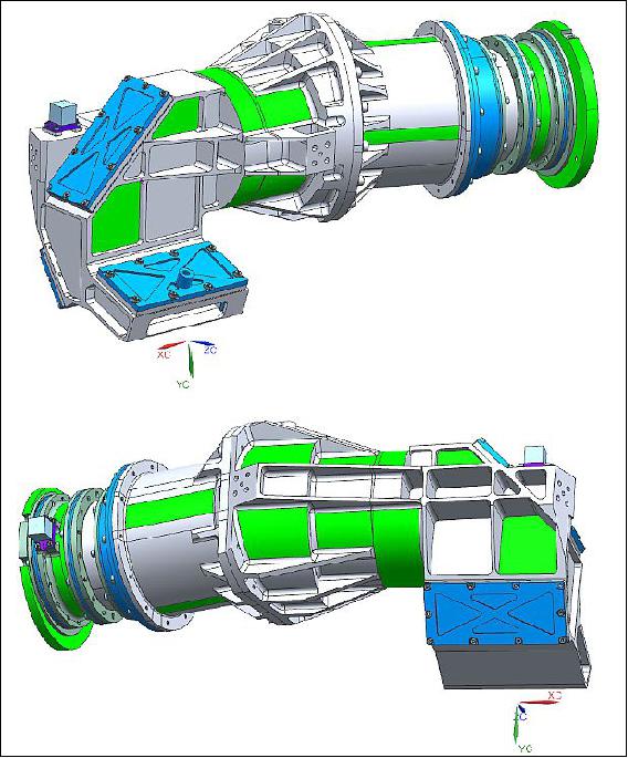
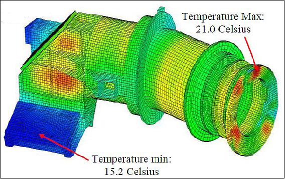
The heaters are located externally as shown Figure 32 with a couple closest to the detection module. The residual gradients in non-operational modes is depicted Figure 33.
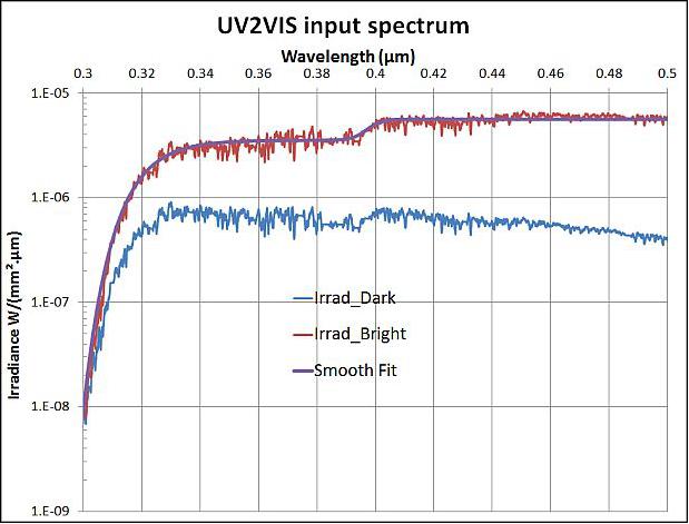
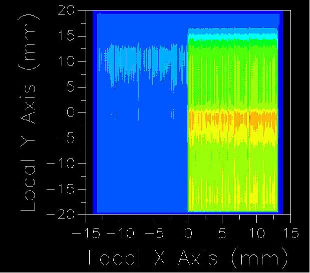
UV2VIS Spectro Optic stray light and narcissus: Stray light control is the main concern in designing this Spectro Optic. The stray light is specified not to affect the measured radiance in a black & white spatial non-uniform scene with the exception of the transition zone of few spaces sampling distance as depicted in Figure 35. The general target for stray light is most difficult to achieve in the short wavelength part due to the drop of the reference scene spectral radiance shown Figure 34.
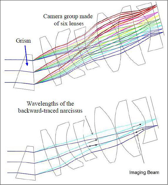
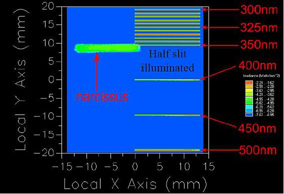
The dominant contributors are in field ghosts due to double reflections between optical surfaces including CCD sensitive area which corresponds to the narcissus. Other contributors are in field scattering due to effect of imperfect polish of optical surfaces or contamination, out of field scattering from of the mechanical mount structure within the SO and also the contribution coming from the rear face of the entrance slit. Diffracted light is considered negligible at these wavelengths.
The same paradigm is used for all the modeling activities using monochromatic point source illumination, empirical formulation of BSDF (Bidirectional Scattering Distribution Function) properties of surfaces including roughness and contamination and finally superposition and summation obtained by weighting taken into account the instrument spectral response function and scene spectral radiance. The stray light analysis program computes by tracing large numbers of rays. They tend to give very noisy results and a large amount of 2 x 10⁷ starting rays and lengthy computing time up to 2½ days is needed for some detailed calculations.
The proposed approach for stray light mitigation purpose considers oversized of free mechanical aperture of optical surfaces with respect to the minimum clear aperture by at least 2 mm. Two physical stops are implemented with one corresponding to the aperture close to pupil plane near the grating and the other the shadow mask on the rear surface. The adopted lens optical layout also takes into account machining constraints with capability to implement blackened vanes mounted on several lens barrels as shown Figure 36.
A severe criticality is found for the ghost image contribution with the grating detector ghost path as seen Figure 37 and Figure 38. The incident light hits the detector, where it is reflected back towards the grating. The diffraction in reflection guides the rays again towards the detector. The way forward consists of re-optimizing the optical design in order to increase the marginal ray angle of incidence.
References
1) "Sentinel-5," ESA, URL: https://sentinel.esa.int/web/sentinel/missions/sentinel-5
2) https://sentinel.esa.int/web/sentinel/missions/sentinel-5
3) "Copernicus: new name for European Earth Observation Program," European Commission Press Release, Dec. 12, 2012, URL: http://europa.eu/rapid/press-release_IP-12-1345_en.htm
4) Bernd Sierk, Jean-Loup Bézy, Jérôme Caron, Roland Meynard, Ben Veihelmann, Paul Ingmann, "The GMES Sentinel-5 mission for operational atmospheric monitoring: Status and Developments," Proceedings of the ICSO (International Conference on Space Optics), Ajaccio, Corsica, France, Oct. 9-12, 2012, paper: ICSO-069
5) Eleni Paliouras, "The GMES Space Component and Service Support Activities," Padua, Italy, Sept. 16, 2010, URL: http://www.fp7-space.eu/infoday2010/16/05_Paliouras-ESA_GMES.pdf
6) "EUMETSAT Council approves EPS-SG Preparatory Program and extends Indian Ocean service," EUMETSAT Press Release, Nov. 16, 2012, URL: http://www.eumetsat.int/Home/Main/News/Press_Releases/825429?l=en
7) Paul Ingmann, Yasjka Meijer, Ben Veihelmann, "Status Overview of the GMES Missions Sentinel-4, Sentinel-5 and Sentinel-5p," Proceedings of ATMOS 2012 - Advances in Atmospheric Science and Applications, Bruges, Belgium, June 18-22, 2012, ESA SP-708, Nov. 2012, URL of presentation: http://congrexprojects.com/docs/12m06-docs2/4-the-atmosphere-related-sentinels_ingmann_asc2012.pdf
8) "Monitoring air quality takes next step," ESA, March 28, 2014, URL: http://www.esa.int/Our_Activities/Observing_the_Earth/Copernicus/Monitoring-air_quality_takes_next_step
9) "MetOp Second Generation instruments," ESA, March 9, 2011, http://www.esa.int/esaLP/SEM95PXTVKG_LPmetop_0.html
10) "Sentinel-5 satellite description," ESA, URL: https://sentinel.esa.int/web/sentinel/missions/sentinel-5/satellite-description
11) "Instrument Payload," ESA, URL: https://sentinel.esa.int/web/sentinel/missions/sentinel-5/instrument-payload
12) Luisa Ferreira, Markus Melf, Wolfgang Seefelder, Abelardo Pérez Albinana, Matthias Erdmann, Didier Martin , "Copernicus Sentinel-5 for Atmospheric Monitoring:Design, Performance and Development," Proceedings of the 68th IAC (International Astronautical Congress), Adelaide, Australia, 25-29 Sept. 2017, paper: IAC-17-B1.3.2
13) Abelardo Pérez Albiñana, Matthias Erdmann, Norrie Wright, Didier Martin, Markus Melf, Peter Bartsch, Wolfgang Seefelder, "Sentinel-5: the new generation European operational atmospheric chemistry mission in polar orbit," Proceedings of SPIE 10403, 'Infrared Remote Sensing and Instrumentation XXV,' 104030P , 30 August 2017, SPIE Optical Engineering and Applications, 2017, San Diego, CA, USA, doi: 10.1117/12.2268875, http://dx.doi.org/10.1117/12.2268875
14) "Sentinel-5," Airbus DS, URL: http://www.space-airbusds.com/media/document/10607tl-sentinel-5-lr.pdf
15) J. Langen, P. Ingmann, Y. Meijer, R. Munro, C. Retscher, B. Veihelmann, "Copernicus Sentinel-5: Long-Term Global Monitoring of Atmospheric Composition," ATMOS Conference 2015, Heraklion, Crete, Greece, June 8-12, 2015, URL: http://seom.esa.int/atmos2015/files/presentation76.pdf
16) Jérôme Caron, Jean-Loup Bézy, Grégory Bazalgette, Courrèges-Lacoste, Bernd Sierk, Roland Meynart, Michael Richert, Didier Loiseaux, "Polarization scramblers in Earth observing spectrometers: lessons learned from Sentinel-4 and -5 phases A/B1," Proceedings of the ICSO (International Conference on Space Optics), Ajaccio, Corse, France, Oct. 9-12, 2012, ICSO-139, URL: http://congrex.nl/icso/2012/papers/FPICSO-139.pdf
17) R. Le Goff, G. Dubroca, D. Majcherczak, D. Loiseaux, M. Bauer, V. Kirschner, "Design of Sentinel-5 UV2VIS Spectrometer Optic," Proceedings of the 67th IAC (International Astronautical Congress), Guadalajara, Mexico, Sept. 26-30, 2016, paper: IAC-16,B1,3,2
The information compiled and edited in this article was provided by Herbert J. Kramer from his documentation of: "Observation of the Earth and Its Environment: Survey of Missions and Sensors" (Springer Verlag) as well as many other sources after the publication of the 4th edition in 2002.