DarkCarb Infrared Imaging Minisatellite
EO
Quick facts
Overview
| Mission type | EO |
DarkCarb Infrared Imaging Minisatellite
DarkCarb Satellite Payload Overview References
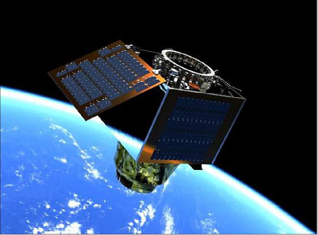
DarkCarb is a pioneering Earth observation (EO) satellite, under development at SSTL (Surrey Satellite Technology Ltd , Guildford, UK), designed to acquire high resolution Mid Wave Infrared (MWIR) imagery and video from LEO (Low Earth Orbit). The mission will set a precedent in IR performance from a small and capable satellite platform while maintaining the SSTL cost effective approach thereby enabling a spacecraft price which makes building constellations, capable of delivering rapid re-visit and wide area coverage, an attractive and worthwhile commercial investment. 1) 2)
Over the last 35 years, SSTL has been at the forefront of small satellite design and innovation. With over 70 small satellites launched, ranging in applications from Earth Observation, Communications, Navigation, Science and Technology Demonstrations, SSTL has gained invaluable experience using a flexible design approach and rapid development thereby delivering reliable satellite missions at low-cost and within short timescales.
As the market moves towards small satellite constellations and the desire for multispectral data grows, demand for low-cost and reliable spacecraft offering a range of sensors, has been increasing. SSTL, building on experience gained in the small satellite and constellation business, as well as innovative ‘miniaturization’, has developed a series of spacecraft to meet the needs of this expanding market. Based on the low-cost Carbonite series of platforms, SSTL has designed three highly innovative, and in some cases ground-breaking, satellites. 3)
• Carbonite – 1 m optical imager in the visible range
• DarkCarb – 3.5 m mid-wave infrared (MWIR) imager
• CarbSAR – 0.5 m X-band synthetic aperture radar (SAR) imager
The Carbonite Platform
The DarkCarb satellite is based on SSTL’s Carbonite series of platforms – small, low-cost, capable, platforms designed and built for rapid-delivery first launched in July 2015 with Carbonite-1. Carbonite-1 was the 1st generation satellite on a roadmap to develop a new product at a low price point and deliver high resolution imagery and video within a shortened delivery schedule. Built in just 6 months it applied SSTL’s experience and design approach to exploit new, commercially developed technologies, protocols and processes, extensive use of commercial off-the-shelf (COTS) components, and SSTL’s automated production capabilities to deliver a high utility satellite providing high resolution imagery. It also demonstrated the use of video imagery acquired from space, opening up a whole new range of applications to the commercial sector. Carbonite-2 Figure 1, the second technology demonstrator in the Carbonite series, was launched in January 2018 and introduced several design improvements and additional experiments.
Carbonite-1 and Carbonite-2 established a standard for high utility satellites at low cost and short schedule but were designed as technology demonstrators. The current iteration of the Carbonite platform being used on DarkCarb is the next step in the program – a commercial offering building on the experience and technological advancements of the first two platforms. It features a number of enhancements compared to its predecessors to provide superior performance and functionality, as well as reduced costs and schedule through manufacturing improvements. Some of the new platform features include:
• SSTL’s latest suite of core avionics which combines previously separate OBC, AOCS, GPS, and TTC receiver and transmitter functionality into a single module. This has the advantage of significantly reducing mass and volume, as well as improving power consumption, allowing more power to be allocated to payload operations.
• Next generation data recorder, the HSDR-X (High Speed Data Recorder-X-band downlink), which combines a high speed data recorder and mass memory unit with embedded X-band exciter functionality, based on previous SSTL technology. 4) The HSDR-X offers a reduction in mass, volume, power, and cost, and an increase in capacity and bandwidth, with 500 GB of storage. In addition SSTL has also been developing techniques to reduce the amount of data downlinked, using multi-channel JPEG-LS image compression. Further reduction in data can be achieved by performing radiometric calibration and dark pixel correction on board leading to improvements in the compression ratio. Another angle for example is the generation of thumbnails on board and processing to determine the level of cloud cover and suitability for download.
• The integrated RF architecture introduces flexibility in the RF solution, allowing variable modulation schemes and data rates with no hardware changes. The baseline data rate is 500 Mbit/s with potential for up to 1 Gbit/s or more, depending on the modulation scheme used.
• The HSDR-X also provides additional payload specific functionality with an FMC daughterboard interface which can provide a bespoke module for data processing and a shift to a software-based processing architecture which allows easier accommodation of third party algorithms, faster development times, and in-orbit reconfiguration.
• Increased redundancy. The avionics and payload chain (excluding the imager) are fully redundant, with an electrically redundant propulsion system.
• Water propulsion system capable of providing more than 130m/s delta-V, allowing the selection of lower orbits to improve GSD (Ground Sample Distance), and other orbital maneuvers such as altitude maintenance or phasing. The water-based system reduces launch site handling costs and schedule, and the modular nature of the propulsion system means the number of tanks can be reduced depending on customer requirements.
• Automated LEOP (Launch and Early Orbit Phase) following separation from the launcher. Minimal operator intervention will be required to get the satellite to a de-tumbled, power and thermally safe attitude, reducing cost and commissioning time.
The platform uses a forward-motion compensation (FMC) mode which allows the satellite to point and stare at a particular location over a prolonged period of time; this mode is used to capture still images or video at up to 25 frames per second (FPS), providing up to 60 s of video for a particular target at extreme roll angles. The platform is also agile, capable of moving from one target to another over roll angles of up to ±45º.
Spacecraft
DarkCarb is a highly innovative satellite designed to fill a gap in the Earth observation market by providing MWIR imagery at low cost and high resolution, Figure 1. MWIR imagery provides several advantages over visible imagery, including the ability to image both night and day under any lighting condition, providing additional temporal information by comparing temperature changes on a still target, and using temperature information to monitor items otherwise invisible to visible sensors.
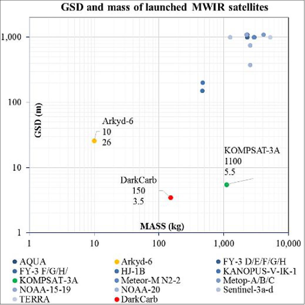
The current commercial market for MWIR imagers is a trade-off between mass and resolution – the higher resolution platforms typically have masses of >1,000 kg, as seen in Figure 2. SSTL decided to approach this market with the same ‘smallsat mentality’ and flexible design approach which has been so successfully applied to its current range of Earth observation satellites.
The payload is based on a Mercury Cadmium Telluride (MCT) cooled, 8 µm pixel detector and will provide a 3.5 m GSD (at 500 km) and a FOV of 3.5 x 4.4 km. The detector produces imagery in the 3.7-5.0 µm MWIR waveband and has a thermal sensitivity (Noise Equivalent Temperature Difference) NETD) of 30 mK, with the complete end to end system targeting <2 K at 200 K. The top level specifications for the DarkCarb satellite are shown in Table 1.
Reference orbit | 500 km SSO at 09:30 LTAN (Local Time of Ascending Node) |
Design lifetime | 5 years |
Satellite mass | ~130 kg |
GSD (Ground Sample Distance) | 3.5 m at Nadir |
FOV (Field of View) | 3.5 x 4.4 km |
Off-pointing capability | ±45º |
Imager sensor | 8 µm pixel |
Bands | MWIR 3.7-5.0 µm |
Thermal sensitivity | MDTD (Minimum Detectable Temperature Difference) <2 K @ 300 K |
Imaging modes | Video, Snap |
Imaging operation | Day and night |
Delta-V | >130 m/s |
Data rate (minimum) | 500 Mbit/s |
Data storage | 500 GB |
DarkCarb Applications
MWIR imagery provides some key differentiators from visible imagery and combined with the capabilities of the DarkCarb platform the applications are wide-ranging. MWIR imagery will provide the capability to differentiate between objects and surfaces of different temperature and emissivity, providing complementary information to traditional visible imagery and the ability to extend imaging opportunities into night time, as well as different lighting conditions in daytime imaging.
DarkCarb can provide utility in the mapping of heat islands in urban areas, including the detection of buildings or installations emitting a significant level of heat. This can be applied to support environmental activities or detecting waste and pollution spills or discharge from sewage plants and power plants, assuming the pollutants are warmer than the surrounding water bodies.
DarkCarb also has the potential to assist with disaster support activities for wildfires, volcanic eruptions and flooding, for example, and may also provide utility in urban areas to support environmental activities that are threatening our world.
The video generation capability adds unique advantages over traditional MWIR imagery, allowing the detection of highly dynamic features in scenes to be provided and extracted, such as 3D profiles, movement tracking, and speed measurement. Frames can also be stacked to provide improved image quality.
DarkCarb Constellation Possibilities
The current trend in the Earth Observation (EO) market is to deploy large constellations of satellites in order to achieve high temporal resolution and global coverage. The low-cost nature of the design makes the DarkCarb satellite ideal for a multi-satellite constellation, allowing users to build up a large constellation for rapid-revisit. The platforms’ low-mass and volume means multiple satellites can potentially be launched at the same time, allowing a full constellation of different platforms to be operational within months.
As the market moves towards small satellite constellations and the desire for multi-spectral data grows, demand for low-cost and reliable spacecraft offering a range of sensors, by themselves or in groups, has also been increasing. Multi-sensor constellations provide the capability to maximize the advantages of each sensor type by combining different data sets thus increasing content and improving accuracy of the available information from a particular target or location of interest. DarkCarb would add considerable value to a mixed sensor constellation – allowing data collection to be extended into night time and providing interesting possibilities for data fusion for a wide range of applications, potentially not accessible before due to the large and costly nature of previous MWIR imaging satellites.
Sensor Complement
Optical system: The DarkCarb imager has been optimized to produce high resolution in the mid-wave infrared (MWIR) waveband 3.7-5.0 µm with a GSD of 3.5 m from an orbit of 500 km. The detector is an mercury cadmium telluride (MCT) based 8µm pitch device with a format of 1280 x 1024 placed in an f/2.8 dewar connected to an active liner cryogenic cooler operating ~90 K.
The imager optical design is based on a Ritchey-Chretien (R-C) telescope that is coupled to a relay lens. The relay lens re-images the optical system stop onto the detector dewar cold shield. This ensures that the telescope aperture is minimized, and so the ensemble may be considered a Keplerian telescope as opposed to a Gaussian telescope. The R-C telescope has hyperbolic surfaces for both primary and secondary mirrors in order to minimize volume and correct off-axis aberrations.
The dewar cold shield has an optical speed of f/2.8, however in order to reduce the telescope aperture and thus the mass and volume of the imager, a f-number mismatch has been applied as per Gat et al [5)]. In this case, the optical system optical speed has been reduced to f/3.6 (clear aperture of 315 mm) and the dewar cold shield is re-imaged onto the secondary mirror, which has been reduced in size to match the f/3.6 speed. The f/2.8 optical speed, which essentially is an over-aperture at the secondary mirror, is catered for by using a low reflectivity annulus mounted around the secondary mirror, also known as the secondary cold shield. This cold shield minimizes any reflections that may lead to stray light, and as the name suggests the shield is cooled in order to reduce any emitted thermal photons. 5)
Thermal modelling suggests that unlike Gat et al, the secondary cold shield needs only to be cooled down to -20ºC rather than the dewar cryogenic temperature of below -180ºC. This ensures that the required minimum detectable temperature difference (MDTD) requirement of less than 2 K at a scene temperature of 300 K is met but without cryogenically cooling the secondary cold shield. In order to reduce parasitic thermal radiation the relay lens is optimized at a relative aperture of f/2.8, so that the only component producing extraneous thermal photons in the field of view of the detector is the secondary cold shield.
The optical design has been athermalized passively so that a focus mechanism is not required and that focus is maintained throughout the orbit over the lifetime of the mission. Due to the reduction in system optical speed to f/3.6, the red end of the operating waveband is blurred due to effects of diffraction. However the polychromatic modulation transfer function (MTF) is recovered by the application of a suitable image processing algorithm. Similarly, image processing is applied to recover the image as is normal in thermal imaging by performing a suitable non-uniformity correction.
The imager has been designed for nominal operation on the eclipse side, i.e. night-time operation, and in this case, sense the full MWIR waveband of the detector 3.7-5.0 µm. This allows the maximum detectable signal to be imaged. However noting that solar radiation swamps emitted radiation in the waveband 4.4-5.0 µm and in order to reduce ambiguity in the imagery a ‘day’ filter is placed in the optical system in the same place as the calibration thermal target. This allows only emitted thermal radiation to be sensed during the daytime. In order to ensure that there is no need to compensate for the focal shift during day and night imaging, a ‘night’ filter is used similarly to the day filter, although of course in this case the filter has no selective filtering.
The innovative design of the DarkCarb imager has produced the smallest possible optical layout for an imager which has a very high spatial resolution of 3.5 m and small MDTD (Minimum Detectable Temperature Difference) of less than 2 K.
Mechanical system: The requirements that the optical system demands from the imager structure are largely typical for an imager, with some specific and unusual features, to be achieved in the context of being able to support flexible design and rapid manufacture at a commercial cost point.
For any imager the regulation of the primary to secondary (M1-M2) separation is crucial to maintaining the focused image coincident with the detector, and the longer wavelength of an MWIR system has a larger depth of focus compared with an imager working in the visible band thus negating the need for an additional focus mechanism. The structure holding the mirrors ideally has the same thermal coefficient of expansion as that of the mirrors, making the system naturally athermal. Choice of low expansion materials (low expansion glass ceramic and Carbon composite / Invar) makes the whole system stable to flight temperature variations, both orbital and seasonal.
Carbon composite has very good properties, being lightweight and can be engineered to have a Coefficient of Thermal Expansion (CTE) very close to that of glass ceramic. It does have significant drawbacks in terms of its design complexity, manufacturability (high pre-preg cost and lead time, minimum order cost, limited shelf life, high tooling and lay up cost, limited scalability) and performance (moisture outgassing). Invar structures have the potential to possess adequate stability, whilst being quick to design and analyze, facilitating design flexibility and fast assembly which can be easily scaled for series production.
Historically, Invar structures have suffered from temporal instability with low CTE being achieved by quenching the material, locking in residual stress in the structure causing unpredictable distortion. Both these issues have been addressed by selection of Invar alloy with low carbon content which is now readily available, and long term stability is achieved through annealing and artificial ageing of the structure after vacuum brazing.
To achieve the goal of fast design and manufacture DarkCarb has been designed to use an Invar structure and is constructed from simple machined components, drawn tubes and sheet metal parts assembled together using the vacuum brazing process.
The principal structural component is the bulkhead which is made as a closed box section from two shells brazed together. The bulkhead supports the metering truss, the primary mirror and the focal plane structure and provides the mounting interface to the space craft through the imager mounts.
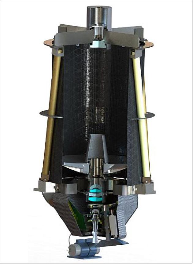
The metering structure is a brazed assembly of components and supports the secondary mirror support structure, Figure 4.
The focal plane structure shown in Figure 5 illustrates how the approach allows complex 3d structures to be built rapidly from sheet metal primitives.
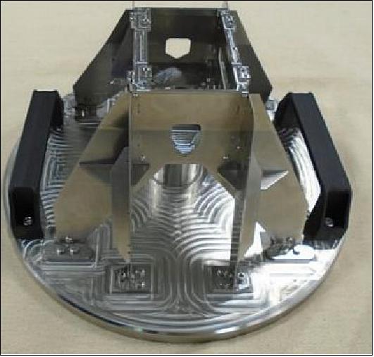
The brazed joint can be considered as monolithic with the components joined, making analysis of the structure straight forward, and machining components from solid brings great flexibility of shape, fastener position, light weighting schemes etc. Long distances within the structure are spanned using precision drawn tubes or sheet metal structures built up from multiple 2d shapes which can be cut accurately and without heat distortion by the water jet process with very short lead times.
Brazing the components together under vacuum at temperatures in excess of 1000ºC requires the components to be accurately located and supported, which is achieved through the use of self-jigging features in the components, assembly jigs and brazing jigs.
After brazing, the flight assembly is aged for 2 days at a lower temperature. On removal from the brazing fixture minimal work is required, to prepare it for integration.
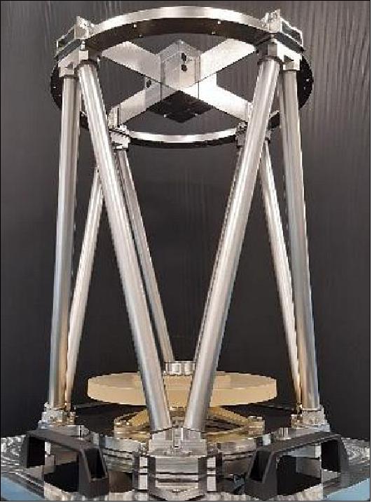
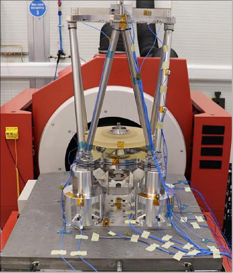
To validate the structural strength this concept offers, an EM (Engineering Model) imager structure was built and subjected to vibration and shock testing, Figure 6. After surviving predicted flight loads with no discernible damage, the vibration level was increased to generate stresses at critical joints equal to the yield stress measured in simple pull test sample, and an extended endurance test was run. After the equivalent of 30 minutes random vibration at flight qualification levels, no damage was detected confirming the robust nature of the design.
Use of Invar requires careful attention to mass control, and thermal management provisions. Although the design is predicted to operate without active thermal control of the metering structure, to mitigate the risk of orbital temperature swings being greater than predicted, the imager embodies distributed heaters to regulate the temperature of the metering struts.
Calibration System
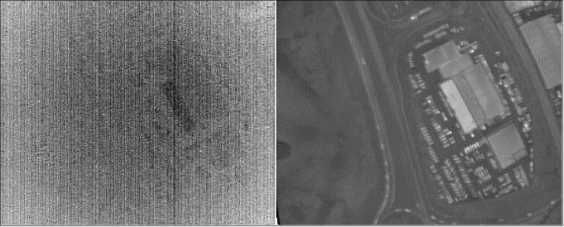
The Need for Calibration: The MCT detector used in the DarkCarb imager is made up of an array of pixels, each of which have their own response to incident thermal radiation. The response of each pixel changes for each power cycle of the detector. The different responses of the pixels cause the raw images from the detector to look like noise and, although they contain lots of information, it is hidden (see LHS of Figure 7). The calibration aims to normalize the response of all these pixels so that a clear image can be formed. This is done by imaging a calibration target which can vary in temperature allowing the response curve of each pixel to be established. The raw pixel values can then be converted to an equivalent black body temperature when viewing ground images. An example of a calibrated image can be seen on the RHS (Right Hand Side) of Figure 7. As the response changes for each power cycle the calibration needs to be recalculated each time the detector is powered on to get the most accurate data possible.
To achieve this a pair of calibration targets have been incorporated into the design which will be used to calibrate the sensor during each imaging session. These targets should be able to cover the entire operational range of the imager and therefore need to be operational between -20ºC and +50ºC.
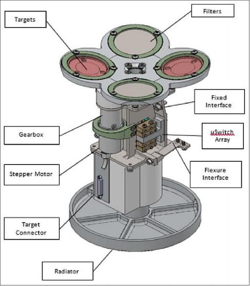
Calibration Wheel: The DarkCarb imager utilizes a novel approach to the calibration target design by placing it in the middle of the optical path as opposed to next to the detector or outside the optical materials. The target has been placed in this location for a multitude of reasons, including thermal design, sizing of the mechanism, and the optical performance. The basic idea of the targets is that they are moved into the optical path during calibration (over which time they are heated to multiple temperatures), and then moved out of the optical path during ground imaging. The design of the calibration wheel which houses these targets is shown in Figure 8. This wheel also includes a day-time and night-time filter which shifts the waveband over which the imager is sensitive depending on viewing conditions. The primary use of these filters is to prevent solar reflections (which mainly occurs under 4.2 µm) during day-time imaging.
Calibration Target Design: Within the mechanism the calibration targets have been designed in such a way that during the calibration process they are as thermally isolated from the rest of the spacecraft as possible to ensure they meet the homogeneity requirements. However after calibration they also need to be able to cool down before the next imaging session. This requirement has influenced the shape, material and bonding method of the targets. The design is currently going through iterations based on ground testing in air and vacuum environments starting at different ambient temperatures. The current design uses copper due to its good thermal properties, however other materials such as silver are being investigated to determine if they achieve higher performance.
The targets are circular in shape with 2 distinct faces; the back which contains the heating element and temperature sensors, and the front which is viewed by the sensor. The front face is treated with a surface finish to provide uniform emissivity. These two faces are joined by a thin circular extrusion which allows for uniform heat transfer to the front face. In orbit the temperature sensors will allow for a closed loop control circuit which will dynamically adjust the calibration paddle temperature.
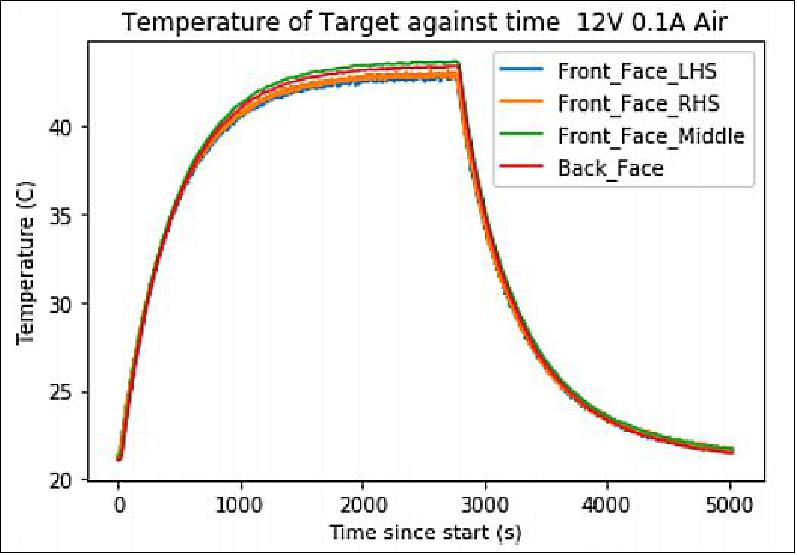
Temperature Profiles: On ground testing of the calibration targets has been completed on representative targets to match the thermal layout of the targets in the calibration mechanism. Temperature sensors were then installed on the front and back face of the test targets to establish the temperature variation across the target and the settling time for different heater power inputs. This work has been completed for temperatures which we would expect to see in orbit. An example of a temperature profile in air can be seen in Figure 9. From the detailed runs in vacuum there was shown to be good temperature correlation <0.5ºC between the thermal sensors.
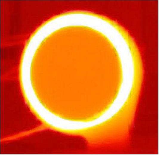
Target Surface Finish: The surface finish applied to the front face of the paddle is vital to its emissivity and overall performance. Three surface finished have been outlined for testing. Each gives a different surface finish which aims to provide a homogeneous radiating surface. Some provide a rough surface finish via blasting, others use a chemical process that forms copper oxide dendrites on the paddle, while space grade black paint that is known to have a uniform emissivity has shown promising results. An example of a blasted paddle at 36º C is shown in Figure 10. The imager will only be viewing the central part of the paddle which shows good homogeneity.
Calibration Mechanism: The Calibration Mechanism as outlined above serves two purposes on the DarkCarb Imager; its primary purpose is to provide the detector with line of sight to thermal reference surfaces, also known as calibration targets, which are used by the imager to self-calibrate prior to any imaging sessions. The mechanism’s secondary purpose is to provide the optics with a choice of two filters, one to use while imaging during daytime and the other to use while imaging during night.
The mechanism houses two identical calibration Targets and both Filters in a wheel which is rotated by the mechanism in order to place any one of these targets and/or filters into the optical path as required by the imager. This wheel is coupled via a conductive shaft to an external radiator, which provides passive cooling to the Targets throughout the spacecraft’s orbit such that they are nominally relatively cold.
During the calibration process, one of the two Targets is rotated by the Mechanism into the field of view of the detector and heated through a number of temperature set points as part of the non-uniformity correction (NUC) calibration. After this process is concluded and the imager is calibrated, the Mechanism rotates the now – hot Target out of the optical path whilst also rotating either the day or night-time filter into the optical path (depending on the time of day and state of illumination of the ground) for the start of an imaging session. The hot Target is then allowed to passively cool outside the optical path in preparation for the next calibration cycle.
SSTL has designed, built and flown a number of different optical mechanisms throughout its history. 6) The Calibration Mechanism is unique among these mechanisms as the majority of its design drivers are thermal, which has introduced new challenges and resulted in some unique features being incorporated into the mechanism.
The decision to cool the targets passively was based on a desire for a simple and efficient solution, as active cooling introduces another thermal input and associated complexity. Passive cooling to the level required by the lowest calibration temperature requires an external radiator, which results in a mechanism which is nominal cold compared to the rest of the imager. This requires special attention to lubrication, tolerances and material selection to ensure that the mechanism does not seize or stall at these low temperatures.
On the other hand, when the calibration targets are heated to the highest calibration temperature, this can create a temperature difference of up to 100ºC across the mechanism. To manage these gradients, and to facilitate the flow of heat through the mechanism, it employs various thermal management features in the form of thermally isolating spacers, mounts and flexures as well as thermally conductive gaskets, radiative links in the form of emissive surfaces as well as careful use of multi-layer insulation (MLI) blankets.
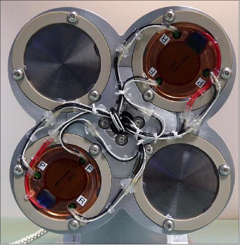
The mechanism’s calibration targets, Figure 12 are designed to provide a uniform spatial and temporal temperature surface to the detector during the calibration sequence. Each Target is instrumented with a number of thin film platinum thermistors and polyimide film heaters which allow their temperature to be controlled in closed loop by the mechanisms’ electronics.
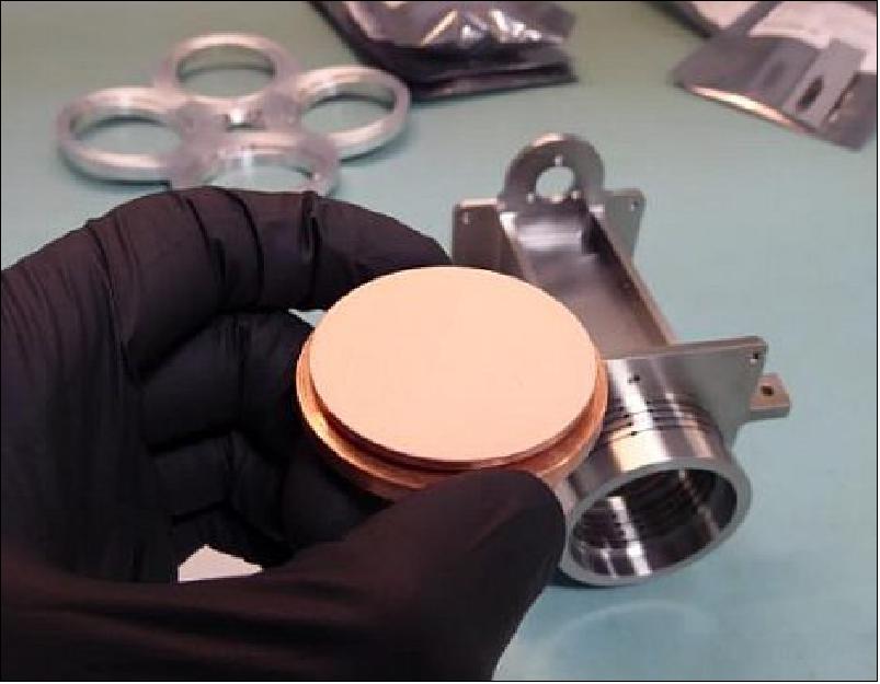
They are bonded into thermally insulating cups to provide a weak conductive link to the wheel and external radiator such that over an orbit they reach temperatures below the 1st NUC temperature. The two targets are identical and provide both a level of redundancy to the imager while facilitating double the number of calibration sequences per orbit.
The mechanism is designed to facilitate the rotation of the wheel, shaft and radiator around their axis. This rotating assembly is supported by a pair of ball bearings selected to provide a low coefficient of friction at low operating temperatures. The ball bearings are preloaded against launch loads by means of compliant feature machined into the titanium housing using wire-EDM. This feature also accommodates differing CTE’s between components.
To drive this rotating assembly, a hybrid stepper motor is coupled to a planetary gearbox, which in turn rotates an anti-backlash pinion. This pinion meshes with a spur gear on the main shaft to provide the required motion. An end stop plate attached to the spur gear engages with a dowel on the housing to limit the angle of rotation to just over 300º and also provides a reference position or datum for the mechanism.
Wiring of the heater and sensors on the calibration targets is routed through the rotating central shaft of the mechanism to one end of a Flexi-Rigid Printed Circuit Board (PCB) or ‘Flexi’. The other end of this Flexi is mounted to a bracket on the static housing. This allows the electrical connection to the heater and sensors to be maintained through the range of rotation of the mechanism, even at low temperature.
The mechanism uses an array of micro-switches to provide an indication of the position of the wheel. The micro-switches, motor, heaters and sensors are all wired to the services module electronics, which provide power and control for the functionality of the mechanism.
Finally, the mechanism housing is mounted to the Focal Plane Support Structure of the imager using both fixed and flexure interfaces to minimize the load imparted into this structure due to differential CTE’s.
Electrical System
The electronics for the imager has three main functions. The operation of the detector and acquisition of the image data is served by the detector proximity electronics and the Front End Electronics (FEE). The operation of the calibration mechanism and control of the temperature of the calibration targets is served by the services module (SM) and the operation and supervision of the cryocooler by the cryocooler controller. These three units communicate with the satellite On-Board Computer (OBC) via the CAN bus and are powered directly from the spacecraft 28 V bus.
The MCT MWIR detector is a COTS item, it is mounted inside the dewar together with two temperature sensing diodes (TSD). Two double rows of pins electrically interface the detector to the Detector Proximity Electronics, Figure 13.
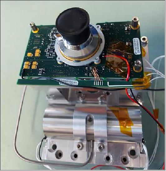
The detector proximity electronics is a single PCB. The main function of this assembly is to convert the analogue outputs of the detector to the digital domain. The detector has eight outputs and these are digitalized with 14 bits resolution and the sampling frequency is 20 Ms/s. The electrical noise of the video path has been kept low, taking into consideration the noise output of the detector itself and full well capacity of the detector pixels the dynamic range of the imager is expected to be over 75dB. At the maximum frame rate of 25fps, data is generated at the rate of approximately 500 Mbit/s and is transferred to the FEE using high speed Low-Voltage Differential Signal (LVDS) differential pairs.
A number of linear power supplies provide all the necessary voltage rails and bias to the detector. The output of some of the rails is adjustable to allow for compensation at end of life radiation effects on the performance of the detector. A number of “housekeeping” ADC (Analog to Digital Converters) monitor the voltage and current of these power rails together with the temperature of sensors on critical parts of this assembly. These monitor continuously the health of the detector and protect it protect in the event of radiation induced single event latch ups.
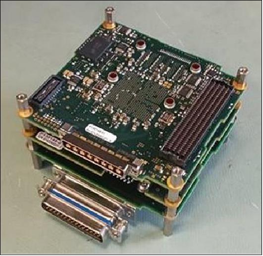
Two flexible PCB circuits connect the detector proximity electronics to the FEE. The FEE is a versatile modular unit and its design allows easy integration and adaptation across the Carbonite range of mission sensors. It is made up as a stack of four PCBs shown in Figure 14; a power supply module, a telemetry/telecommands module, a processing module and a detector interface unit. The detector interface is mission specific and is adapted to serve different detectors used across different types of imagers.
The processing module is designed around a Field Programmable Gate Array (FPGA). This module processes the imagery data from the detector and controls the imaging sequence and timing of both the detector and the ADC. A number of camera parameters can be set before each imaging session. These include the video frame rate, exposure time, detector readout modes, low noise or high dynamic range operation and video duration. The processed detector data is packaged in a CoaXPress compatible protocol and transmitted via a dual redundant link to the data recorder.
The Services Module (SM) utilizes a generic design across the mission range providing motor control, heating, and monitoring of other “Services” required to support an imaging payload in Space. This includes a number of LVDS general purpose inputs as well as analogue monitoring and temperature sensor inputs.
A cryocooler controller has been developed to ensure the required performance is met in the most demanding conditions. The Cooler Electronics is derived from the heritage SSTL wheel and Antenna Pointing Mechanism (APM) electronics design using SSTLs experience to ensure that the design is fit for a space environment.
DarkCarb Image Processing
The processing of the DarkCarb images to give useful information for end-use applications follows a similar series of steps to that used for visible imaging. However, there are aspects that are dependent of characteristics of the spectral bands. As always, the more that is known about the imager the easier it is to convert the raw sensor signals into valuable data.
The DarkCarb image sensor is a photon detector. As a result the output of each pixel is proportional to the radiance it receives. The radiance of interest is that received from the ground, but there will be additional sources which give an offset in the sensor output. One of the challenges in designing an imager in the MWIR is that the wavelengths to which it is sensitive are emitted by all objects that are at the Earth’s temperature, including many parts of the imager itself. The detector is enclosed in a cooled Dewar and the field of view is restricted to help to reduce the unwanted sources of radiation, however the radiation from the earth directly impinges on the optical elements of the imager which are directly in the line of sight of the detector. Careful design of the optics to ensure that none of the unwanted radiance is focussed onto the detector as this manifests as an offset on the pixel values which must be removed by processing. The imager contains temperature sensors that enable the levels of the unwanted sources to be determined as the thermal environment of the imager changes over the orbit and time of year.
In addition to the offset caused by stray radiation reaching the detectors, each pixel within the detector has a slightly different gain and offset. The on-board calibration targets permit measurements of the gain and offset to be made so that a correction can be applied. With correction of stray light and other offsets and the gain corrected, the signals from the detector pixels are each proportional to radiance.
While radiance is the fundamental property of the Earth that the imager measures, ultimately MWIR imagers are used to detect changes in the thermal characteristics of the ground scene. Those are a combination of the temperature and emissivity of objects on the ground –both give useful information about the scene content. Converting radiances into equivalent black-body temperature is performed using Planck’s law and integrating over the relative spectral response of the detector. That response is largely determined by the quantum efficiency of the detector which is fairly flat over the imager’s spectral band.
Similar to silicon detectors for visible there will be defects in the pixel array. DarkCarb used a high-quality state-of-the art detector helping to limit these defects, as part of the calibration process, pixels which have anomalous behavior are identified so that their outputs can be excluded from later stages in the processing.
An important imaging mode of DarkCarb is forward motion compensation (FMC) where the imager is pointed at a fixed point on the ground as the satellite passes overhead. The high frame-rate of the imager gives image sequences that view the ground area from steadily changing directions. This gives greater information about objects on the ground including the detection of objects in motion. It also permits noise reduction and the mitigation of the behavior of anomalous detector pixels – rather than simply replacing a pixel value by interpolating the surrounding ones in a single image, each ground point is imaged by multiple detector pixels over the course of the FMC maneuver.
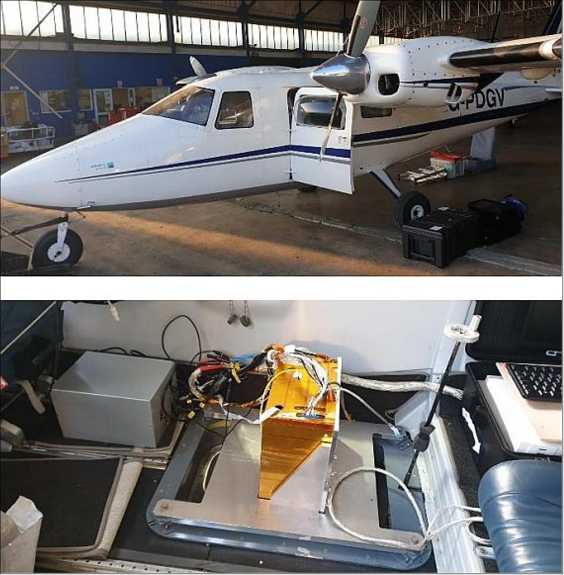
Flight Trials
To explore the imager’s potential, SSTL developed a camera to fly on a small light aircraft complete with flight detector and electronics, with a COTS lens system, see Figure 16. The objective of the trial was to generate imagery that can be used to assess the capability of the in-orbit instrument ahead of that instrument being launched and provide a good understanding of how the imager responds to typical ground scenes. In addition this data allows early development of the processing and calibration chain and will also be used to support customers in developing downstream applications in advance of the first mission.
The camera detects scene radiance which is affected both by the temperature and the emissivity of features in a scene. This allows valuable information about buildings and other objects to be derived during the day or night which is complementary to information from optical imagery. This information includes current and recent activity in a scene, such as recently moved, or moving, vehicles and the operational status of facilities and industrial installations.
The two images shown in Figure 16 and Figure 17 were captured at night and are a selection from an extended acquisition captured at 25 frames/s from an altitude of 2400 m (the corresponding google earth images are also shown for reference). Dark areas in the image are cool, or have low emissivity, and bright areas are warm, or have relative higher emissivity. The scenes shown have a wide range of equivalent black-body temperatures. The images have been processed to bring out the detail in the colder areas of the scene for visual interpretation and, as a result there is saturation of hot features in the image.
Figure 16 shows John Lennon Airport in Speke where parked planes are visible against the apron. Again the dark object is a building with a metal roof.
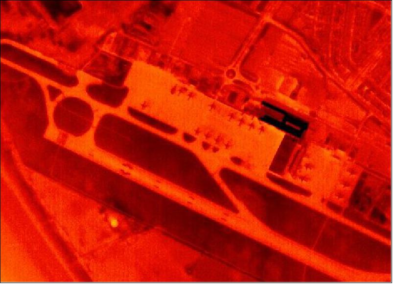
Figure 17 is the Stanlow Refinery in Ellesmere Port UK. The image clearly shows parts of the refinery that are likely to be emitting significant amounts of heat compared to others. The two black rectangles close to the center of the image are buildings that are likely to have low emissivity as well as being colder than much of the refinery. In the top right of the image, the mixing of warmer water from a side channel into the cooler river can also be clearly seen in the upper right corner.

In summary, SSTL’s development of the high performance generic carbonite smallsat platform with multi payload capability is well suited to the DarkCarb mission.
The DarkCarb MWIR payload is progressing fast and is on track be ready for deployment into orbit in 2022. As demonstrated in this paper, the flight trials have further shown the unique nature a MWIR system can bring to address challenges facing the world today from climate to security and defence. Additionally the airborne data is being used to develop the downstream image processing chain and bespoke applications in advance of spacecraft operational data. Customers are also using the MWIR data identifying new markets unforeseen to date, especially when considered with data fusion.
The DarkCarb development is taking the Carbonite series one step closer to the goals of smallsat mixed sensor constellations. SSTL has designed a set of small satellite platforms with three highly innovative payloads in the visible, MWIR, and X-band radar wavelengths. The low-cost nature of the platforms combined with their high-performance capabilities, particularly video capabilities, has opened the door for a commercially viable mixed-sensor constellation, easier access to data, and a large number of potentially new applications not previously available.
SSTL’s proven track record of smallsat engineering, trusted approach and novel payload designs incorporating new techniques presented herein truly show the capability of smallsats such as DarkCarb are endless.
References
1) Andrew Haslehurst, Rachel Bird, Trevor Wood, Calem Whiting, Bena Mero, Harbinder Rana, Matt Price, Camilla Weiss, Diego Angarita-Jaimes, James Bell, Tasos Matheopoulos, John Gliby, Martin Sweeting, ”DarkCarb: An Innovative Approach to Infrared Imaging,” Proceedings of the 35th Annual AIAA/USU Virtual Conference on Small Satellites, August 7-12, 2021, Logan, UT, USA, paper: SSC21-VI-06, URL: https://digitalcommons.usu.edu/cgi/viewcontent.cgi?article=5050&context=smallsat
2) https://www.sstl.co.uk/getmedia/6a9cc3bf-5bd5-469b-9a74-e689557ed959/SSTL-DARKCARB.pdf
3) Camilla Weiss, et al., ”A New Dimension in Small Satellite Constellations,” IAC-19-B4.7.1, 70th International Astronautical Congress 2019, Washington D. C., USA.
4) D. Cooke et al., ”HSDR-X – Design Choices in Maximising Data Returns from Small Satellite Missions,” IAC-20-B4-6A-12, 71st International Astronautical Congress 2020
5) Nahum Gat, Jingyi Zhang, Ming De Li, Liang Chen, Hector Gurrola, ”Variable cold stop for matching IR cameras to multiple f-number optics,” SPIE Proceedings, Volume 6542, 'Infrared Technology and Applications XXXIII; 65420Y (2007), Defense and Security Symposium, 14 May 2007, Orlando, Florida, United States, https://doi.org/10.1117/12.720812
6) Nigel Phillips, Alizee Malavart, Mark Ferris, ”A fully integrated focus mechanism for a high resolution camera,” Proceedings of the 16th European Space Mechanisms and Tribology Symposium 2015’, Bilbao, Spain, 23–25 September 2015 (ESA SP-737, September 2015), URL: https://www.esmats.eu/esmatspapers/pastpapers/pdfs/2015/phillips1.pdf
The information compiled and edited in this article was provided by Herbert J. Kramer from his documentation of: ”Observation of the Earth and Its Environment: Survey of Missions and Sensors” (Springer Verlag) as well as many other sources after the publication of the 4th edition in 2002. - Comments and corrections to this article are always welcome for further updates (eoportal@symbios.space).