DEMETER (Detection of Electromagnetic Emissions Transmitted from Earthquake Regions)
EO
Mission complete
CNES
ISL
Quick facts
Overview
| Mission type | EO |
| Agency | CNES |
| Mission status | Mission complete |
| Launch date | 29 Jun 2004 |
| End of life date | 10 Dec 2010 |
| Measurement domain | Gravity and Magnetic Fields |
| Measurement category | Gravity, Magnetic and Geodynamic measurements |
| Measurement detailed | Magnetic field (scalar), Magnetic field (vector) |
| Instruments | ISL, IDP, IMSC, IAP, ICE |
| Instrument type | Space environment, Magnetic field, Other |
| CEOS EO Handbook | See DEMETER (Detection of Electromagnetic Emissions Transmitted from Earthquake Regions) summary |
DEMETER (Detection of Electromagnetic Emissions Transmitted from Earthquake Regions)
DEMETER is a French microsatellite mission (the first mission of the CNES microsatellite program referred to as Myriade) with the objective to observe geophysical parameters of the terrestrial environment. This involves the study of ionospheric perturbations (measurement of electromagnetic waves and their effects), caused by natural phenomena, such as earthquakes and volcanic eruptions, or resulting from human activities (power lines, VLF, HF broadcasting). Of particular interest is the potential occurrence of electromagnetic perturbations in relation to earthquakes. One hypothesis is that they might offer an early warning prior to earthquakes or eruptions. 1) 2) 3) 4) 5) 6) 7) 8) 9)
The scientific participants in the DEMETER project are: LPCE (Laboratoire de Physique et de Chimie de l'Environnement d'Orléans), CETP (Centre d'etude des Environnements Terrestre et Planetaire) in Velizy/ Saint-Maur, IPG-Paris (Institut de Physique du Globe de Paris), CESR (Centre d'Etude Spatiale des Rayonnements) in Toulouse, and ESA/ESTEC. LPCE is responsible for the science payload. Note: In Greek mythology, Demeter, daughter of Cronus and Rhea, is the goddess of vegetation and fecundity.
The secondary DEMETER technology requirements of the mission will allow the demonstration of:
• An advanced payload telemetry system including a solid-state mass memory of 8 Gbit and an X-band transmitter at 16.8 Mbit/s
• A system of autonomous orbit control (AOC) relying on a GPS receiver and a navigator
• A pyrotechnic priming device fired by a laser, and thermal protection performance of the spacecraft
• Performance of solar cell string (ASPI experiment)
• An experiment of characterization of thermal insulation ageing.
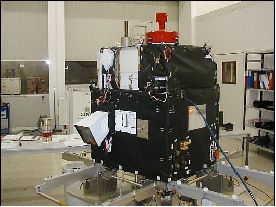
Spacecraft
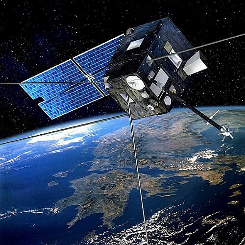
The satellite is of a box-like structure with dimensions of 60 cm x 60 cm x 85 cm (Myriade platform). A single wing of two solar panels is used for power generation. The S/C is three-axis stabilized (Earth pointing) with a pointing accuracy of a < 5º for coarse mode and < 0.1º in fine mode. Attitude sensing is provided by a star sensor, a three-axis magnetometer and three wide range sun sensors; attitude actuation is provided by reaction wheels which are unloaded by magnetorquers. A GPS TopStar 3000 receiver (L1 frequency, Alcatel) provides real-time onboard orbit data. The AOC-GPS experiment provides autonomous orbit control using the GPS receiver. S/C power (200 W EOL) is provided by a steerable sun array (2 panels) using AsGa solar cells with an efficiency of 26% (in addition, lithium ion battery with a capacity of 14 Ah). A PCDU (Power Conditioning and Distribution Unit) is in charge of: 10) 11)
- Launcher separation detection to connect the main non regulated bar to the battery
- Battery regulation
- Power distribution to equipment and payload (regulated voltages or voltages of 22-37 V)
- Thrusters and magneto-actuator commands
- Pyro lines distribution
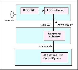
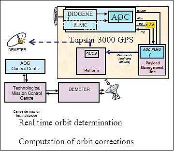
The AOC (Autonomous Orbit Control) technology demonstration experiment uses the DIOGENE (Détermination immédiate d'orbite par GPS et navigateur embarqué) navigator, included in the TopStar-3000 G1 GPS receiver, which provides real-time navigation data every 30 s. 12) 13)
The TopStar-3000 G1 used for AOC is a 12 channel spaceborne multimission GPS L1-band receiver developed by TAS (Thales Alenia Space). The software of the receiver includes a navigation Kalman filter using algorithms developed at CNES. DIOGENE performs propagation of the state vector with an accurate propagation model of forces and updates the state vector with all available GPS measurements. The DIOGENE measured position accuracy on DEMETER is ~ 5 m (3D, 1σ). The receiver provides also a “snapshot” position using a least squares method.
The DIOGENE provides very stable and accurate environment which contributed to the excellent results of the autonomous orbit control experiment. Thanks to AOC, autonomous orbit control is no longer considered a theoretical and risky future possibility, but as a real and credible option.
Hydrazine thrusters perform orbit maneuvers (4.5 kg of hydrazine, 4 thrusters of 1 N each; delta v of up to 80 m/s). Any loss of attitude measurement must be avoided during either the slew maneuvers or the thrust phase. As a consequence, in this mode, attitude will be derived from the integration of gyro measurements (FOG system).
All onboard data handling is provided by OBC (transputer T805 @ 20 MHz), the standard bus employs serial asynchronous links (RS422/RS485). The S/C mass of DEMETER is 129 kg, the design life is 2 years. EADS Astrium SAS, in partnership with CNES, designed and developed the microsatellite.
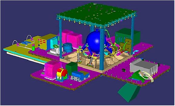
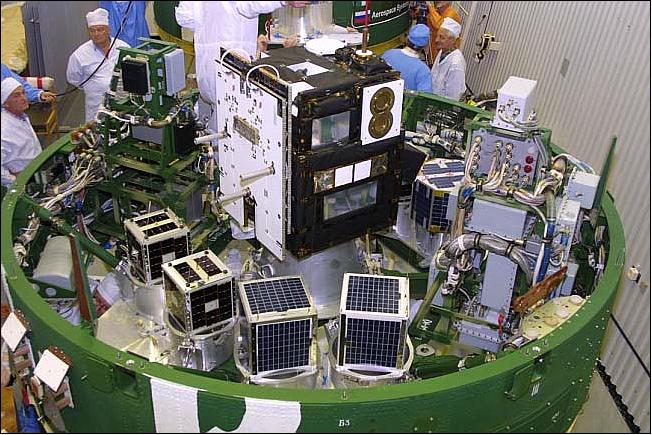
RF communications: The payload recorder has a capacity of 8 Gbit (using 128 Mbit flash memory EEPROM chips). RF communications are provided in S-band (TT&C) with a downlink data rate of up to 400 kbit/s and an uplink of up to 20 kbit/s. The data modulation scheme is QPSK (1/2 Nyquist filter) with Viterbi encoding and Reed-Solomon (RS) concatenated encoding. The CCSDS communication protocol is used. In addition, there is an X-band downlink with a data rate of 16.8 Mbit/s. The X-band is used for the downlink of science data.
Orbit: Sun-synchronous circular orbit, altitude = 710 km, inclination = 98.23º. Local equatorial crossing on ascending node at 22:15 hours.
Note: The orbit was lowered to 660 km in December 2005, without a change in the ascending node.
Orbit | LEO (Low Earth Orbit); DEMETER: 715 km, SSO |
Pointing | Earth pointing (DEMETER); Sun or inertial pointing |
Stabilization | 3-axis; Typical accuracy: coarse mode < 5º; fine mode < 0.1 º; stability: < 3'/s |
Telemetry | CCSDS, convolutional and RS coding |
Localization | Doppler measurement; Accuracy: 1 km (LEO), 10 km (GTO) |
Data | Ground synchronization; onboard accuracy: < 0.5 s |
Power | Steerable sun generator; AsGa solar cells(200 W EOL); |
Spacecraft mass | Total: 130 kg; Payload weight: 50 kg |
Propulsion | Hydrazine, delta-v : 80 m/s; 4 thrusters 1 N |
High-rate TM data | X-band transmitter 16.8 Mbit/s; Memory : 8 Gbit (Flash) |
GPS receiver | TopStar 3000 |
Launch
DEMETER was launched on June 29, 2004 as the primary payload on a Dnepr launcher from Baikonur, Kazakhstan (launch provider: ISC Kosmotras, Moscow). Secondary payloads on this mission were: SaudiSat-2, AKS-1, AMSAT OE, LatinSat-C, LatinSat-D, SaudiComsat1, SaudiComsat2, UniSat-3, and Celestis-04.
Mission Status
• The DEMETER mission was retired on December 9, 2010 after more than 6.5 years on orbit. The final science commands established by the science ground segment at LPC2E (Chemistry and Physics of the Environment and Space Laboratory) was received on board Demeter at 9:03 on December 7, 2010. This command brought to a conclusion Demeter's Science Mission on the December 9, 2010. 14) 15)
- The DEMETER tank passivation operations were completed in February 2011.
- The electric passivation operations took place on March 17, 2011. The satellite went silent on March in direct visibility of the Kiruna station, after more than 5 years of good and faithful services for an initial planned lifetime of two years.
The DEMETER mission, the first MYRIADE microsatellite developped and launched by the CNES, leaves the project a rich heritage of six years of data which have allowed scientists to significantly improve our knowledge of the ionosphere. Its data will continue to be used in studying the link between ionospheric perturbations and seismic and volcanic activity.
• The satellite and its payload are operating nominally in 2010. The plans call for operations to continue until the end of 2010. 16)
After retirement of the science mission by the end of 2010, an in-flight experiment session is foreseen for the first part of 2011 to enrich the knowledge of equipment performances after > 5.5 years of in-flight operations - prior to de-orbit procedures of the spacecraft. 17) 18)
Aside from the primary mission, the autonomous orbit control mechanism was implemented within the spacecraft software and was being used as a technology demonstrator. This demo closes the loop between online orbit restitution on board through GPS receiver measurements and thruster burns to fulfil the ground programmed criteria of: position on orbit and ground track. Figures 7 and 8 highlight the behavior evidenced in flight on more than 150 maneuvers. The overall experienced availability is close to 90% (Ref. 17).
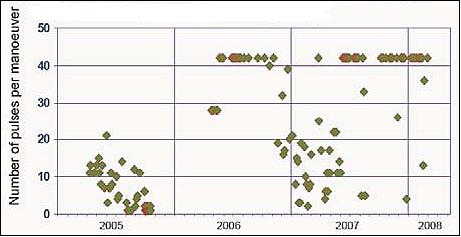
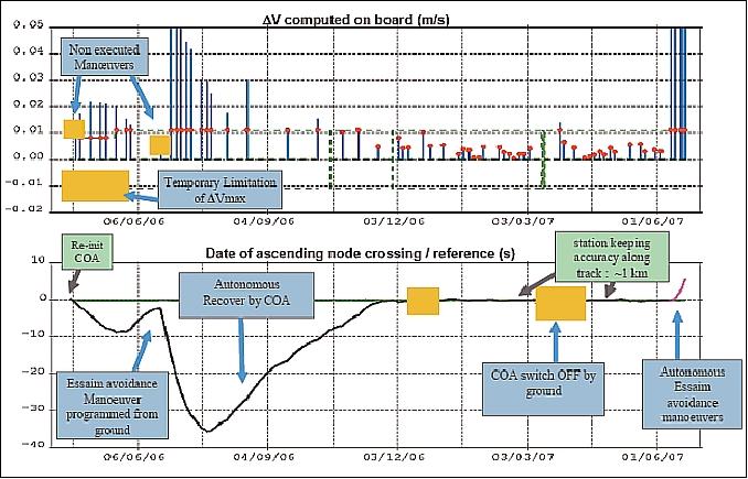
• The altitude of the DEMETER orbit was lowered from 710 km to 660 km in December 2005, without a change in the ascending node.
• In December 2005, the mission was extended by three years. 19)
• The S/C was commissioned two months after launch (end of Aug. 2004). In-orbit performances exceed those required and estimated before launch.
• An in-flight AOC (Autonomous Orbit Control) demonstration has been carried out in 2005. After several months of in-orbit validation (from July 2004 to March 2005) that proved that the onboard software was functioning correctly, the propulsion system could be activated. Orbit maneuvers were then performed autonomously (without any ground intervention) from April to October 2005. - The experiment has been very successful from an operational point of view but also with regard to the station-keeping accuracy achieved [thanks to the GPS receiver and propulsion subsystem performances (1 N hydrazine thrusters providing reproducible 62 ms pulses generating < 1 cm/s ΔV)]. In the routine phase the ground tracks at the equator were controlled to 100-200 m, and in the “continuous” phase the ascending nodes crossing times were controlled to better than 8 milliseconds. 20)
• In December 2005, the project management decided to lower the operational altitude from 710 km to 660 km - this lower altitude favors a more natural reentry capability of the spacecraft within a period of 25 years. The maneuver was executed in January 2006.
Sensor Complement
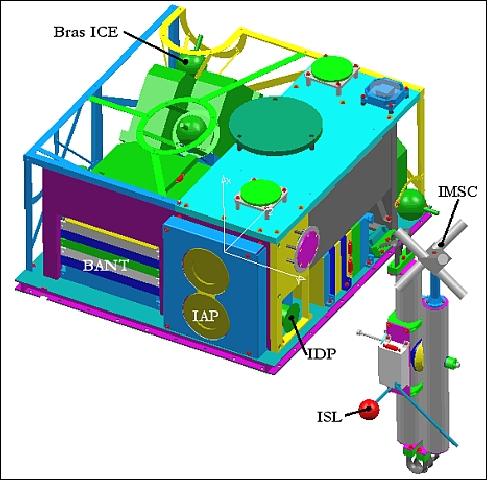
The DEMETER payload is dedicated to the observation and characterisation of the ionosphère with the aim of linking measured perturbations of this environment to seismic and volcanic activity. 21)
Parameter | Measurement Range | Parameter | Measurement Range |
Frequency range, B | 10 Hz - 17 kHz | Frequency range, E | DC to 3.5 MHz |
Sensitivity B | 2x10⁻⁵ nT Hz-1/2 at 1 kHz | Sensitivity E | 0.2 μV Hz-1/2 at 500 kHz |
Particles, electrons | 30 keV - 10 MeV | Ionic density | 5 x 10² - 5 x 10⁶ ion/cm3 |
Ionic temperature | 1000 - 5000 K | Ionic composition | H+, He+, O+, NO+ |
Electron density | 102 - 5 x 106 cm-3 | Electron temperature | 500 - 3000 K |
IMSC (Instrument Magnetometre Search Coil)
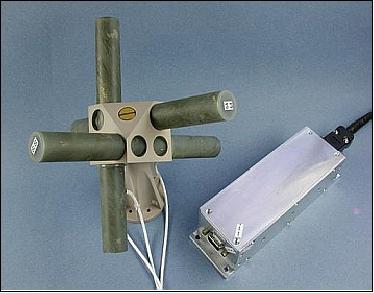
IMSC or three-axis Search Coil Magnetometer of CNRS/LPCE. The objective is to measure the magnetic field components (B) in the frequency range of 10 Hz to 18 kHz. The magnetic vector is measured by the current induced by a coil that is wound around a micro metal bar and by an orthogonal three-antenna system, mounted on a deployable boom of 1.9 m length.
IMSC is composed of 3 orthogonal magnetic antennae (search coil type) linked to a pre-amplifier unit with a shielded cable of 80 cm. The search coil magnetometer consists of a core in permalloy (high permeability material) on which are wound a main coil with several thousand turns (12000) of copper wire and a secondary coil with a few turns. The core is a 170 mm rod with a 4 x 4 mm cross-section. 23)
IPD (Instrument Detecteur de Plasma
IPD or Plasma Detector Instrument of CNRS/CESR. The objective is to measure the energy spectrum of electrons, at right angles to the magnetic field, in the energy range of 30 keV to 10 MeV. The information is needed to estimate the disturbances in the radiation belts induced by earthquakes.
The IDP sensor head comprises a collimator in Aluminum, light material particularly well adapted to minimize the bremsstrahlung. The collimator is designed to provide a view angle of ~ 30º.
Detector | - Implanted silicon |
External shielding | 2 mm Al |
Foil for protons and photons rejection | 6 mm Al |
Instrument mass, power | 0.525 kg, 895 mW |
Energy range (e-) | 60 keV û ~ 600 keV, 256 channels |
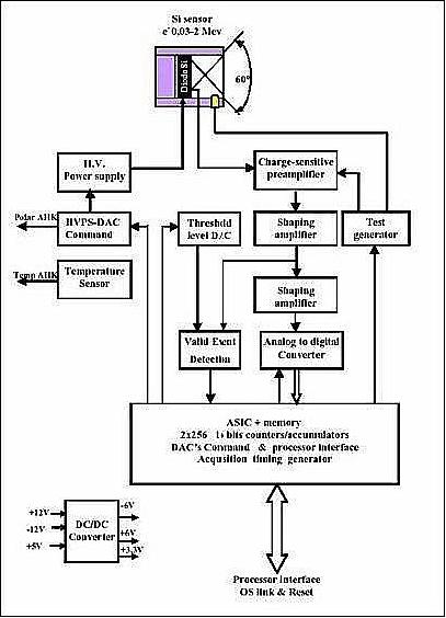
The instrument electronics are shown in Figure 11. The signal coming from the silicon diode is detected with a low-noise charge sensitive preamplifier. The total charge Q created by the passage of a ionizing radiation is converted to an electric impulse. Its height is proportional to the energy of the incident particle. In solid, and particularly in semi-conductors, the ionization of the medium shows itself by the transfer of electrons from the valence band to the conduction band. An electron-hole pair is created in the semiconductor.
The amplitude of the collected impulse dV is proportional to the charge Q and therefore to the deposited energy. The impulse is amplified and shaped. But the length of the trailing edge of the impulse of several ms is incompatible with the need to be able to encode them with a repetition frequency reaching up to 0.5 MHz. The shaping circuit reduces the length of the impulses, and modifies them in order to allow a numerical encoding. Simultaneously, the analog signals are applied to a low level threshold discriminator. The digitalization of the analog signal is made by an ADC (Analog-to-Digital Converter) that carries out a linear analog to digital conversion of dV in 256 channels.
ISL (Instrument Sonde de Langmuir)
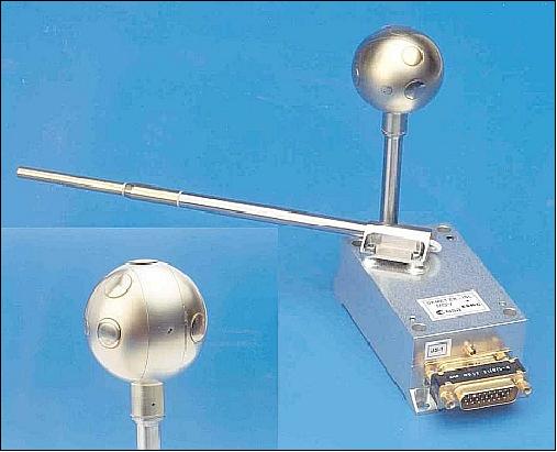
ISL or Langmuir Probe Instrument of ESA/ESTEC [joint project of ESA, LPCE, and the Institute of Atmospheric Physics, Prague, Czech Republic ]. The instrument, a new design, is used to measure the total plasma density in the range of 100 to 5 x 10⁶ particles/cm3, the electron temperature in the 500-3000 K range, and the satellite potential in the range of ± 5 V. The instrument consists of two Langmuir probes, one is cylindrical the other is spherical with a 6 cm diameter segmented probe. The plasma density and temperature are determined from the Langmuir probe current-voltage curve. 24) 25)
ICE (Instrument Champ Electrique
ICE or Electric Field Instrument of CNRS/CETP. The objective is the measurement of the vector components of the Earth's electric field in the frequency range from DC to 3 MHz. EFI consists of an antenna system featuring four spherical electrodes placed at the end of 8 m deployable booms. 26) 27)
IAP (Instrument Analyseur de Plasma)
IAP or Plasma Analyzer Instrument of CNRS/CETP. The objective is the measurement of ionospheric plasma parameters (density, temperature, and energy distribution). IAP is a two-analyzer spectrometer measurering the ion density, composition, temperature and flow velocity. 28)
IAP provides a nearly continuous survey of the main parameters of the thermal ion population with two main objectives. The first one is to detect disturbances in the ionosphere that may arise from the coupling between seismic events on the ground and the upper atmosphere and ionosphere. The second objective is to provide with a sufficient time resolution the ionospheric parameters such as the plasma density and the ion composition that are needed to analyze the plasma wave data from the ICE and IMSC experiments. In addition the IAP observations allow to build a large database that can be used in the frame of space weather studies, for example to analyze the dynamics of the mid-latitude ionosphere in response to magnetic storms.
Modes of Operation
There are two main modes of operation: a burst mode which is triggered when the satellite is above given seismic zones, and elsewhere a survey mode. For example the corresponding recorded data by the wave experiment are:
• Burst mode:
- Waveforms of the three magnetic and the three electric components in the ELF range up to 1 kHz
- Waveforms of one magnetic and one electric component in the VLF range up to 17 kHz
- Spectra of one electric component up to 3.3 MHz.
• Survey mode:
- Spectra of one magnetic and one electric component up to 17 kHz. Three possible combinations of frequency and time resolutions can be selected by telecommand
- Spectra of one electric component up to 3.3 MHz.
In both modes, the three electric components are recorded in the ULF range, and either a magnetic or an electric component in the VLF range is used as input for an onboard neural network which will detect whistlers.
References
1) F. Buisson, “The DEMETER Program: A Pathfinder to a High Performance Micro Satellite Line” AIAA/USU Conference on Small Satellites,” Logan, UT, USA, Aug. 11-14, 2003, SSC03-VI-6
2) DEMETER brochure of CNES, provided by Bernard Tatry
3) M. Parrot, “The microsatellite DEMETER,” Journal of Geodynamics, Vol. 33, 2002, pp. 535-541
4) http://smsc.cnes.fr/DEMETER/
5) M. H. Thoby, “Myriade: CNES Micro-Satellite Program,” AIAA/USU Conference on Small Satellites, Logan UT, Aug.13-16, 2001, SSC01-I-8
6) T. Cussac, F. Buisson, M. Parrot, “The DEMETER Program: Mission and Satellite Description - Early Flight Results,” Proceedings of IAC 2004, Vancouver, Canada, Oct. 4-8, 2004, IAC-04-IAA.4.11.2.04
7) Bernard Tatry, Marie-Anne Clair, Francois Buisson, “Small Satellites CNES Programme - Missions Flown and in Preparation, Lessons Learnt, Success Conditions,” Proceedings of the 20th Annual AIAA/USU Conference on Small Satellites, Logan, UT, Aug. 14-17, 2006, paper: SSC06-IV-2
8) Thibery Cussac, Marie-Anne Clair, Pascale Ultré-Guerard, François Buisson, Gérard Lassalle-Balier, Michel Ledu, Christian Elisabelar, Xavier Passot, Nelly Rey, “The Demeter microsatellite and ground segment,” Planetary and Space Science, Volume 54, Issue 5, April 2006, pp. 413-427
9) “Demeter and the Earth’s fields,” E-Space& Science, CNES, Oct. 14, 2008, URL: http://smsc.cnes.fr/DEMETER/ESS26_en.pdf
10) http://smsc.cnes.fr/DEMETER/GP_satellite.htm
11) A. Lamy, M.-C. Chrameau, D. Laurichesse, M. Grondin, R. Bertrand, “Experiment of Autonomous Orbit Control on the DEMETER Satellite,” 18th International Symposium on Space Flight Dynamics, Munich, Germany, Oct. 11-15, 2004
12) D. Dassaud, J.-L. Issler, L. Ries, A. R. De Latour, M. Grodin, “Contribution to Spacecraft Navigation and Timing with GPS and Galileo,” Autonomous Orbit Control Thanks to GPS onboard DEMETER, 58th IAC (International Astronautical Congress), International Space Expo, Hyderabad, India, Sept. 24-28, 2007, IAC-07-B2.3.06
13) Florence Duchevet, Alain Lamy, “DEMETER: Experience Feedback on Operations with an Autonomous Orbit Control Demonstrator,” SpaceOps 2008 Conference, Heidelberg, Germany, May 12-16, 2008, AIAA 2008-3238
14) “DEMETER latest news,” URL: http://smsc.cnes.fr/DEMETER/GP_actualite.htm
15) http://demeter.cnrs-orleans.fr/
16) Information was provided by Steven Hosford of CNES, Toulouse, France
17) Philippe Landiech, Paul Rodrigues, and all CNES mini and micro satellite teams, “Overview on CNES Microsatellite Missions: in flight, under development and next,” Proceedings of the 7th IAA Symposium on Small Satellites for Earth Observation, Berlin, Germany, May 4-7, 2009, IAA-B7-0102
18) Bernard Cabrières, Fernand Alby, Christian Cazaux, “Satellite end of life constraints : technical and organisational solutions,” Proceedings of the 61st IAC (International Astronautical Congress), Prague, Czech Republic, Sept. 27-Oct. 1, 2010, IAC-10.B6.2.7
19) C. Bastien Thiry, F. Serene, H. Darnes, F. Duchevet, “DEMETER and PARASOL after 2 years in orbit: where are we?,” Proceedings of the 4S Symposium: `Small Satellite Systems and Services,' Chia Laguna Sardinia, Italy, Sept. 25-29, 2006, ESA SP-618
20) A. Lamy, M.-C. Charmeau, R. Bertrand, D. Laurichesse, “Experiment of Autonomous Orbit Control of DEMETER: In-Flight Results,” Proceedings of 25th ISTS (International Symposium on Space Technology and Science) and 19th ISSFD (International Symposium on Space Flight Dynamics), Kanazawa, Japan, June 4-11, 2006, paper: 2006-d-77
21) http://demeter.cnrs-orleans.fr/
22) http://smsc.cnes.fr/DEMETER/charge_utile.htm
23) “The magnetic field experiment IMSC,” URL: http://demeter.cnrs-orleans.fr/dmt/imscDescription.htm
24) S. Merkallio, “Analysis and Visualization Software for Demeter Langmuir Probe Instrument,” ISSN 0782-607, Helsinki, 2006
25) J.-P. Lebreton, S. Stverak, P. Travnicek, M. Maksimovic, D. Klinge, S. Merikallio, D. Lagoutte, B. Poirier, P.-L. Blelly, Z. Kozacek, M. Salaquarda, “The ISL Langmuir probe experiment processing onboard DEMETER: Scientific objectives, description and first results,” Planetary and Space Science, Vol. 54, Issue 5, April 2006, pp. 472-486
26) J. J. Berthelier, M. Godefroy, F. Leblanc, M. Malingre, M. Menvielle, D. Lagoutte, J. Y. Brochot, F. Colin, F. Elie, C. Legendre, P. Zamora, D. Benoist, Y. Chapuis, J. Artru, R. Pfaff, “ICE, the electric field experiment on DEMETER,” Planetary and Space Science, Vol. 54, Issue 5, April 2006, pp. 456-471
27) http://demeter.cnrs-orleans.fr/dmt/iceDescription.htm
28) J. J. Berthelier, M. Godefroy, F. Leblanc, E. Seran, D. Peschard, P. Gilbert, J.; Artru, “IAP, the thermal plasma analyzer on DEMETER,” Planetary and Space Science, Vol. 54, Issue 5, pp. 487-501.
The information compiled and edited in this article was provided by Herbert J. Kramer from his documentation of: ”Observation of the Earth and Its Environment: Survey of Missions and Sensors” (Springer Verlag) as well as many other sources after the publication of the 4th edition in 2002. - Comments and corrections to this article are always welcome for further updates (eoportal@symbios.space).