ERS-1 (European Remote-Sensing Satellite-1)
EO
ESA
Atmosphere
Ocean
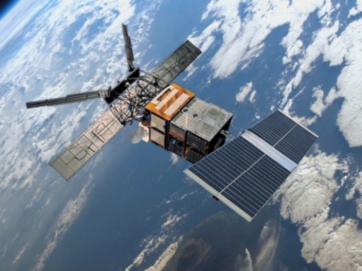
The ERS-1 was the first environmental monitoring satellite developed by ESA. The mission detected land and ocean surface change and provided observation data on oceans, polar ice, vegetation, geology, meteorology and ecology.
Quick facts
Overview
| Mission type | EO |
| Agency | ESA |
| Mission status | Mission complete |
| Launch date | 17 Jul 1991 |
| End of life date | 07 Mar 2000 |
| Measurement domain | Atmosphere, Ocean, Land, Gravity and Magnetic Fields, Snow & Ice |
| Measurement category | Cloud type, amount and cloud top temperature, Liquid water and precipitation rate, Atmospheric Temperature Fields, Aerosols, Multi-purpose imagery (ocean), Radiation budget, Multi-purpose imagery (land), Surface temperature (land), Vegetation, Albedo and reflectance, Gravity, Magnetic and Geodynamic measurements, Surface temperature (ocean), Atmospheric Humidity Fields, Ozone, Landscape topography, Ocean topography/currents, Sea ice cover, edge and thickness, Soil moisture, Snow cover, edge and depth, Ocean surface winds, Ocean wave height and spectrum, Ice sheet topography |
| Measurement detailed | Ocean imagery and water leaving spectral radiance, Aerosol absorption optical depth (column/profile), Precipitation intensity at the surface (liquid or solid), Aerosol optical depth (column/profile), Cloud type, Aerosol Extinction / Backscatter (column/profile), Land surface imagery, Vegetation type, Earth surface albedo, Short-wave Earth surface bi-directional reflectance, Atmospheric specific humidity (column/profile), O3 Mole Fraction, Atmospheric temperature (column/profile), Land surface temperature, Sea surface temperature, Land surface topography, Wind vector over sea surface (horizontal), Sea-ice cover, Snow cover, Soil moisture at the surface, Wind speed over sea surface (horizontal), Sea-ice thickness, Significant wave height, Bathymetry, Geoid, Dominant wave direction, Sea level, Sea-ice type, Glacier motion, Ocean dynamic topography, Dominant wave period, Sea-ice sheet topography |
| Instruments | MWR, ATSR/M, AMI/SAR/Image, AMI/Scatterometer, ERS Comms, ATSR, AMI/SAR/Wave, RA |
| Instrument type | Imaging multi-spectral radiometers (vis/IR), Scatterometers, Communications, Imaging multi-spectral radiometers (passive microwave), Radar altimeters, Imaging microwave radars |
| CEOS EO Handbook | See ERS-1 (European Remote-Sensing Satellite-1) summary |
Related Resources
Summary
Mission Capabilities
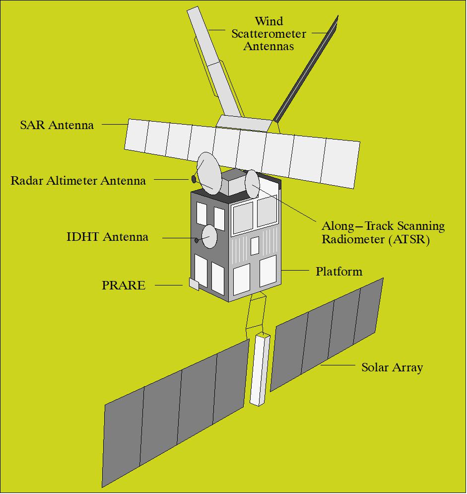
Sensors onboard ERS-1 included:
- Active Microwave Instrument (AMI)
- Radar Altimeter-1 (RA-1)
- Along-Track Scanning Radiometer and Microwave Sounder-1 (ATSR-1)
- Laser Retro-Reflector (LRR)
- Precise Range and Range-Rate Equipment (PRARE).
AMI was a dual-radar which utilised three modes to detect different phenomena on Earth:
- Imaging mode, where C-band measurements were used to conduct imagery of the Earth.
- Wave mode, where the reflectivity of the sea surface caused by surface waves could be processed to identify the length and direction of wave systems.
- Wind Scatterometer Mode (SCAT) used three different antennas to measure sea surface wind speed and direction.
RA-1 operated in Ku-band with two modes (ocean and ice), which provided various ice parameters, wave height, ocean surface elevation for tide and current studies, and ocean surface wind speeds.
ATSR-1 consisted of two radiometers (microwave and infrared), with the main objective of measuring global sea surface temperature for climate change scientists.
LRR was mainly used to ensure the accuracy of satellite tracking from the ground.
PRARE was mainly used for orbit determination and ionospheric corrections to ensure that the other data collected for ocean circulation studies and sea-surface topography was accurate.
Performance Specifications
The spatial resolution was dependent on the operational mode of AMI. In imaging mode, the spatial resolution varied from 10 - 30 m with a swath width of 100 km and an incidence angle of 23°. In wave mode, the spatial resolution was fixed at 30 m with a swath width of 5 km x 5 km, while the scatterometer mode yielded a spatial resolution of 50 km and a swath width of 500 km, with a variable incidence angle. Imaging was completed using a singular C-band frequency wave.
ERS-1 was set to a sun-synchronous near-circular polar orbit with an inclination of 98.52° at an altitude of 782 - 785 km, with an orbital period of approximately 100 minutes.
Space and Hardware Components
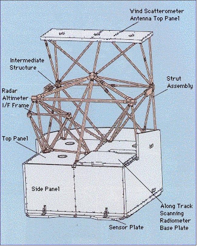
The bus used on ERS-1 was the SPOT MK1 bus, based on the SPOT Multimission Platform that included a service module, propulsion module, payload module and a dual-wing solar array subassembly.
Furthermore, there were ground systems in place to support the satellite’s control and operation, specifically to archive and process instrument data and to satisfy user requirements. These ground stations were located in Italy, Spain and Canada, with the mission control centre in Darmstadt, Germany and system monitoring in Frascati, Italy.
The mission was concluded in 2000 due to the inability to manoeuvre into emergency acquisition mode, where the solar arrays face the sun to regenerate charge in the batteries. However, this mission lasted eight and a half years, which was over three times its nominal mission life.
ERS-1 (European Remote-Sensing Satellite-1)
Spacecraft Launch Mission Status Sensor Complement Ground Segment References
ERS is the first ESA program in Earth observation with the overall objectives to provide environmental monitoring in particular in the microwave spectrum (i.e., regular monitoring of land-surface and ocean-surface processes for change detection).
Coverage of a broad range of disciplines and topics:
- observation of oceans,
- -polar ice,
- land ecology,
- geology,
- forestry,
- wave phenomena,
- bathymetry (water depth),
- atmospheric physics,
- meteorology, etc.
Scientific research: PIPOR (Program for International Polar Ocean Research); PISP (Polar Ice Sheet Proposal). Demonstration of concept and technology for space and ground segments (performance and operational capability). 1) 2) 3) 4) 5) 6)
The ERS program had a pioneering character in the field of instrument development (active sensors), and the introduction and demonstration of advanced observation technologies - a European success story. The ERS preparatory and development program was initiated at ESA in 1981, the C/D phase started in Dec. 1984.
Spacecraft
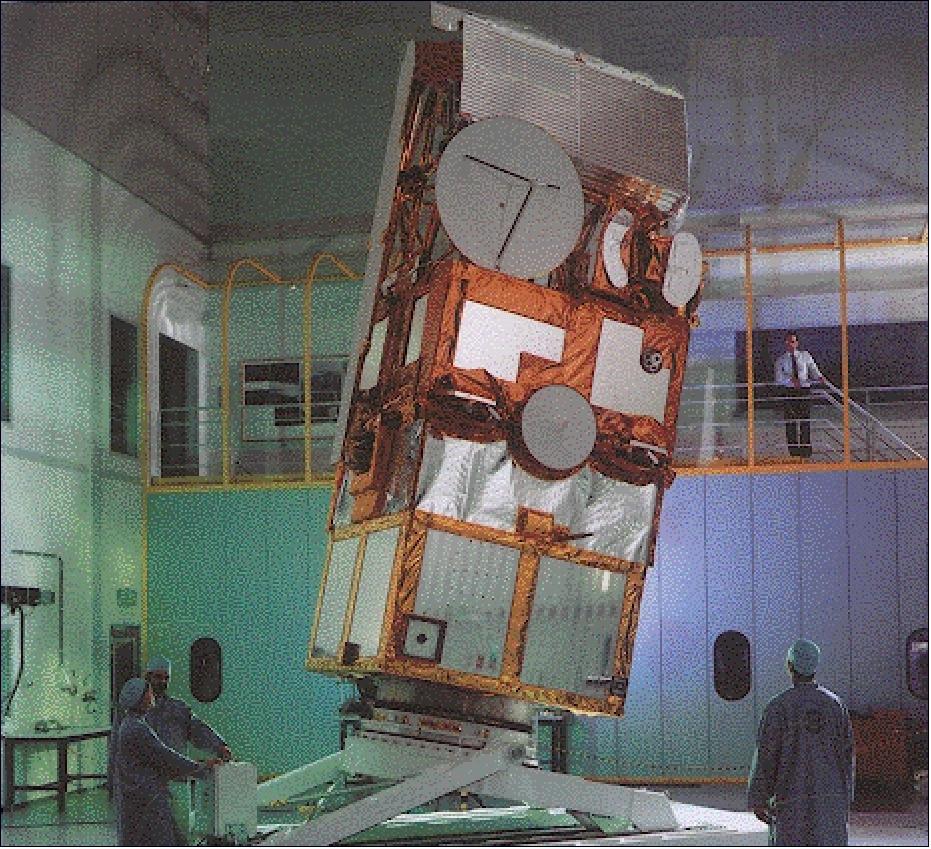
The ERS-1 spacecraft is a three-axis-stabilized Earth-pointing satellite [zero momentum bias with control to 0.11º (pitch/roll) and 0.21º (yaw)]. The platform is a SPOT program bus (SPOT MK1 bus), modified to meet the needs of the ERS missions. The S/C was built by a consortium with DSS (Dornier Satelliten Systeme GmbH) of DASA (DaimlerChrysler Aerospace AG), Friedrichshafen, Germany as prime contractor (since 2000, EADS Astrium GmbH). The payload support module has dimensions of 2 m x 2 m x 3 m (height).
Attitude is measured by several sensors (horizon sensor, narrow-field sun sensors, gyroscopes, wide-field sun sensors). Attitude control by a set of momentum wheels. The payload module consists of PEM (Payload Electronics Module) and ASS (Antenna Support Structure). Thermal control is a passive system complemented by an active heater.
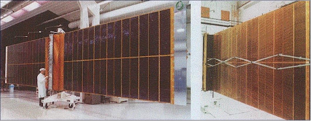
Satellite mass = 2384 kg. The solar array (11.7 m x 2.4 m in size) consists of two 5.8 m x 2.4 m panels and supports a peak payload power of 2600 W. The antenna is a slotted-waveguide array made of metallized CFRP (Carbon Fiber Reinforced Plastic). The battery storage capacity is 2650 Wh. The mission requirements call for an operational period of 2 years with a possible extension of a 3rd year (but reduced mission).
The ERS-1 orbit was maintained with several monopropellant-type thrusters, aligned about the spacecraft's three primary axes, in which hydrazine dissociated exothermically as it is passed over a hot-platinum catalyst. The thrusters were used in different combinations to maintain and modify the satellite's orbit and to adjust its attitude during non-nominal operations. ERS-1 carried 300 kg of hydrazine for orbit maintenance.
Platform | Based on the SPOT Multimission Platform (SPOT MK1 bus) consisting of: |
Electrical power | Payload peak power: ≤ 2600 W; Payload permanent power: ≤ 550 W |
Attitude and Orbital Control | Type: 3 Axes stabilized Earth pointed |
Data handling | Onboard computer (OBC) word length: 16 bits; Payload memory capacity: 20 k words; Payload data exchange: ESA-STD OBDH data bus; each payload instrument contains its own ICU (Interment Control Unit) linked to OBDH (On-Board Data Handling) |
RF communications | Transponder: coherent S-band (2 kbit/s), Transmission power: 50 to 200 mW max; Telemetry rate: 2048 bit/s: Telecommand rate: 200 bit/s; Data downlink: - X-band (105 Mbit/s high rate link for AMI image mode) |
Spacecraft mass, size | 2384 kg (at launch), overall height of 11.8 m |
Launch
The launch of the ERS-1 spacecraft took place on July 17, 1991, on an Ariane-4 vehicle from Kourou, French Guiana.
Orbit
Sun-synchronous near-circular polar orbit, 98.52º inclination, altitude of 782 -785 km period of about 100 minutes (14.3 orbits/day).
The following orbit coverage cycles are defined:
1) Reference orbit - 3-day repeat cycle (high repetition change monitoring with dedicated calibration sites; this orbit was used during the commissioning phase)
2) Ice-Orbit - similar 3-day repeat cycle with a slightly different longitudinal phase. The main limitations of a 3-day cycle are the restricted global coverage for the imaging SAR and the wide separation of the RA-1 tracks.
3) Mapping-Orbit - 35 days repeat cycle (guaranteeing full Earth coverage). This enables SAR imaging of every part of the Earth's surface, with at least twice the frequency of the coverage at middle and high latitudes.
The ERS-1 mission ended on March 10, 2000, due to a failure of the onboard attitude control system. ERS-1 was lost when a failed gyro prevented the S/C from maneuvering into an emergency acquisition mode with its solar panels pointed toward the sun to keep the batteries charged.
ERS-1 generated a wealth of observational data (about 800,000 radar scenes in its first 3 years of operation). The last SAR image was taken on March 7, 2000. This gives a service life of about 8 1/2 years, more than three times its nominal mission life.
The following list provides some program highlights:
1) High-quality observations of all instruments. The availability of C-band SAR imagery in particular opened a wealth of new applications in many fields of the Earth system. In 1993, ERS-1 differential SAR interferometry demonstrated a range precision of 1 cm. This feature provided the ability to detect small changes on Earth's surface:
- detection of landslides;
- evolution of volcanic eruptions;
- detection of surface movement caused by earthquakes;
- horizontal displacement along active faults.
This in turn triggered new projects which enabled precise land motion monitoring on an operational basis based on long-term time series (1992-2003): subsidence, landslides, and seismic risk.
2) The most exciting results of the ERS-1 mission have been in the field of SAR interferometry, where for the first time precise topographic information could be produced in a tandem mission with ERS-2 in the period July 1995 to July 1996. DEMs (Digital Elevation Models) with a 10 m vertical precision could be generated. Also, a strong complementarity of microwave and optical observations was recognized during the tandem mission.
3) Fundamental discoveries about the oceans and atmosphere:
- global wind and wave fields at high spatial and temporal resolution;
- global ocean dynamics and climatic instabilities;
- identification of previously unidentified physical ocean features;
- sea-surface manifestations of atmospheric phenomena.
Mission Status
• October 7, 2021: The Royal Swedish Academy of Sciences has awarded a share of that year's Nobel Prize in Physics to Klaus Hasselman, in acknowledgement of his contribution to "the physical modelling of Earth's climate, quantifying variability and reliably predicting global warming". Hasselman also co-created the ESA's first Earth observation mission, ERS-1. It was the ESA's first Earth observation mission dedicated to understanding the Earth, the European Remote Sensing satellite (ERS-1), was launched on 17 July 1991. At the time, ERS-1 was one of the most sophisticated satellites ever developed and launched by Europe, paving the way to a new era in satellite technology to study the atmosphere, land, oceans and ice.
- The satellite carried a comprehensive payload including an imaging synthetic aperture radar, a radar altimeter and other powerful instruments to measure many aspects of our planet. ERS-1 was then joined by ERS-2 in 1995 which carried an additional sensor for atmospheric ozone research – the Global Ozone Monitoring Experiment. Both satellites exceeded their design life by far, delivering a 20-year stream of continuous data that formed the basis for countless research papers on how the planet works and how it is changing.
- These missions have provided the basis for the routine remote sensing that is now a key aspect of Earth observation. By 1978, the European community had been inspired by Seasat. A series of experiments to understand ocean waves followed, and the preparations for ERS-1 resulted in a series of key reports and results. The synthetic aperture imaging theory led to 2D wave spectra from the Active Microwave Instrument on ERS-1 and the use of these wave spectra products in the ocean models. This legacy extends to the wave mode products from the Copernicus Sentinel-1 radar mission and the use of these products in operational ocean monitoring.
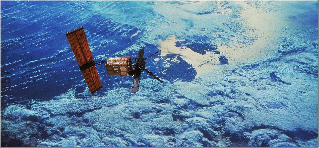
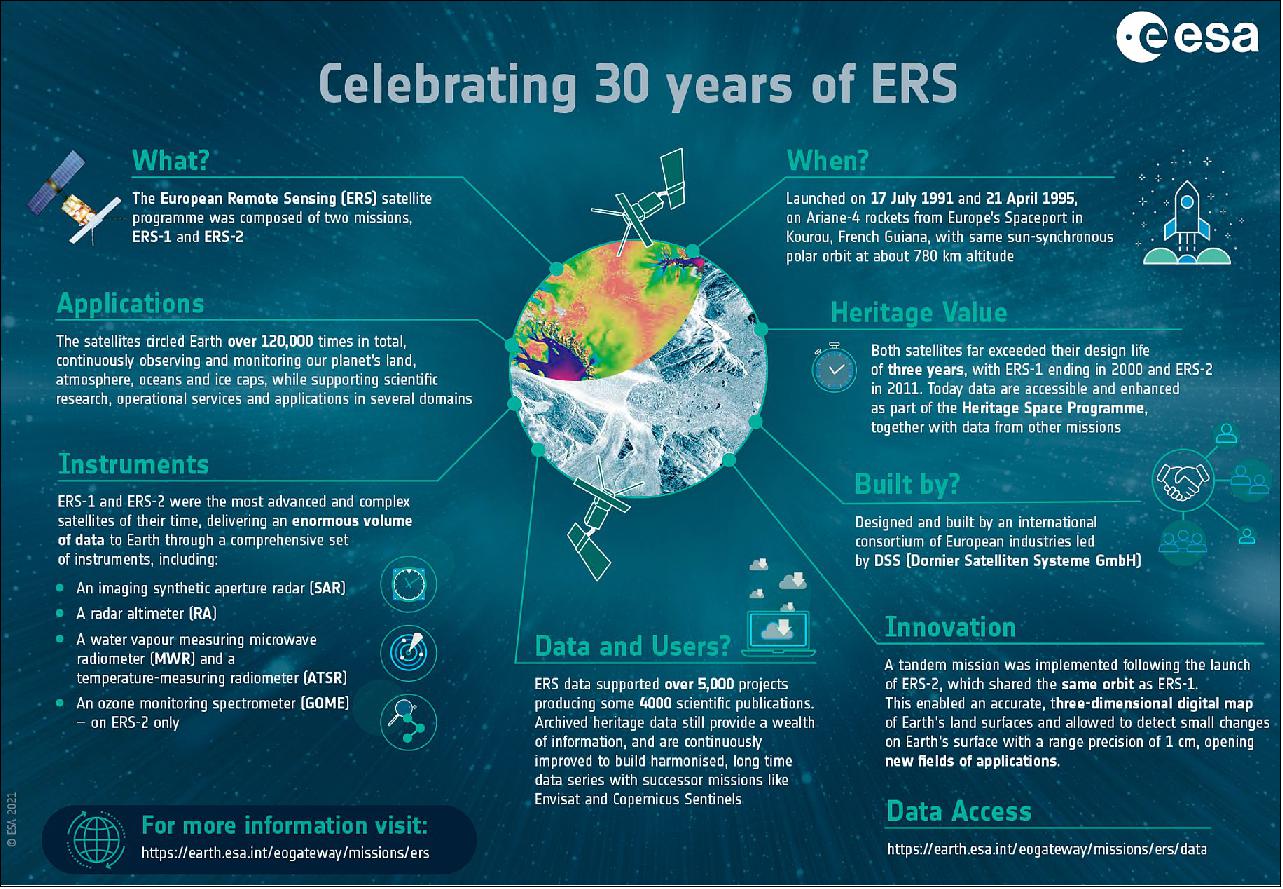
• July 16, 2021: ESA's first Earth observation mission dedicated to understanding our planet, the European Remote Sensing satellite (ERS-1), was launched into orbit on 17 July 1991 – almost 30 years ago today. At the time of its launch, the ERS satellite was one of the most sophisticated spacecraft ever developed and launched by Europe, paving the way for satellite technology in the areas of atmosphere, land, ocean and ice monitoring. Today, we look back at some of the mission's key accomplishments. 8)
- The first satellite, ERS-1, was lofted into orbit by an Ariane-4 launcher in July 1991 and carried the hopes of Europe's scientific community with it. The satellite carried a comprehensive payload including an imaging synthetic aperture radar (SAR), a radar altimeter (RA) and other powerful instruments to measure ocean surface temperature and winds at sea. ERS-1 was then joined by ERS-2 in 1995 which carried an additional sensor for atmospheric ozone research – the Global Ozone Monitoring Experiment (GOME). Shortly after the launch of ERS-2, ESA decided to link the two satellites in the first ‘tandem' mission which lasted for nine months. During this time the increased frequency and level of data available to scientists offered a unique opportunity to observe changes over a very short space of time, as ERS-2's track over the Earth's surface coincided exactly with that of ERS-1 24 hours earlier.
- The high-resolution images acquired along the same ground track by both satellites were used to generate digital elevation models and observe changes in the land surface over short periods. Both satellites exceeded their design lifetime by far, together delivering a 20-year stream of continuous data of Earth's land surfaces, oceans and polar caps. During their lifetime, ERS data supported over 5000 projects producing some 4000 scientific publications. Archived data are still maintained, are accessible and continuously improved in the frame of the Heritage Space Program to build long-term data series with successor missions including Envisat, ESA's family of Earth Explorers and the Copernicus Sentinels.
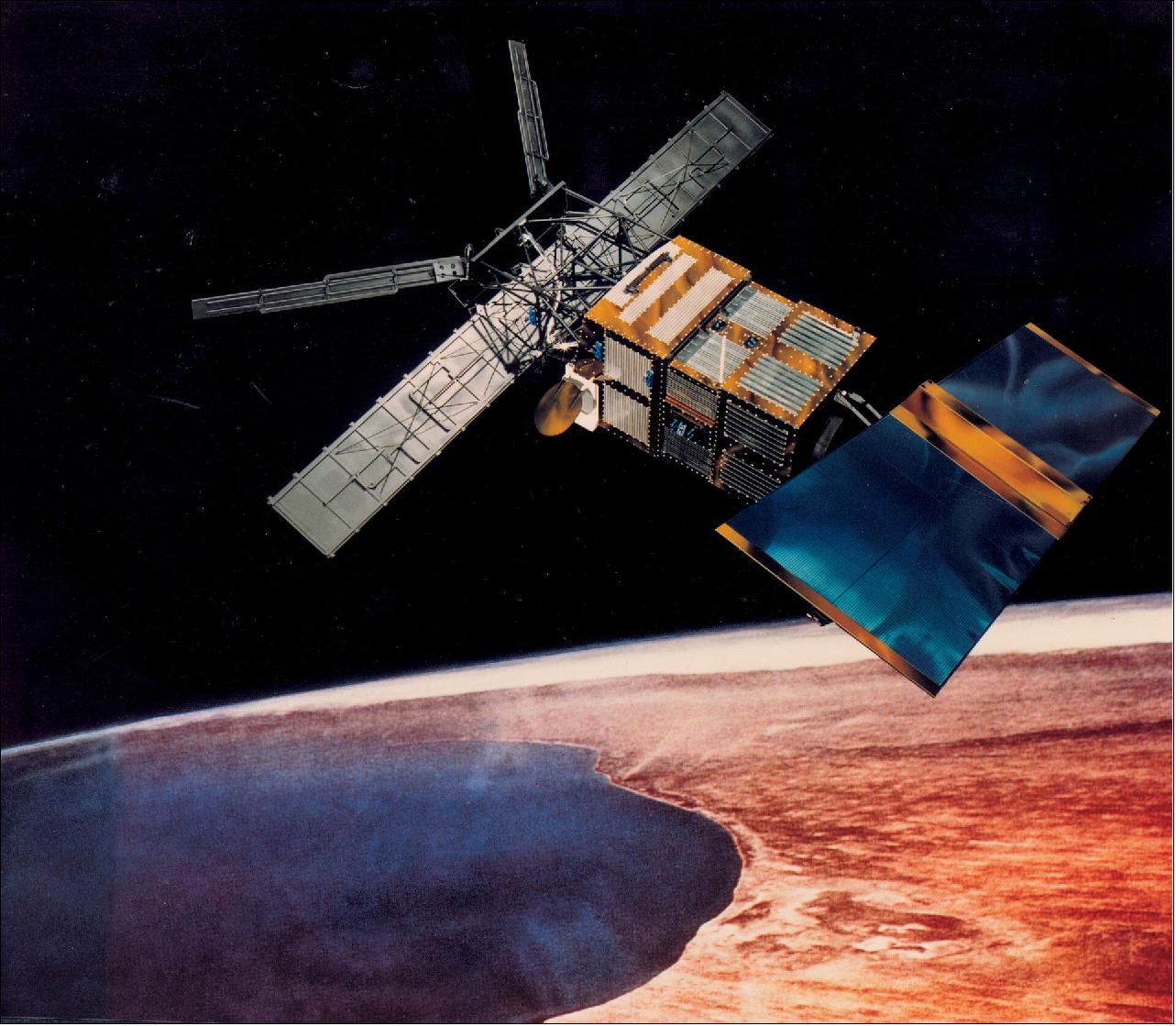
• July 16, 2021: ERS-1 accomplished many feats that newer missions developed on:
- Mapping land: The ERS satellites' comprehensive payload included a synthetic aperture radar to reveal Earth's surface in new detail. SAR data are used for many applications such as agricultural and forest monitoring, flood mapping and geological exploration. Taking these data a step further, SAR interferometric measurements provide insight into the displacement of the ground, making important contributions to our understanding of earthquakes and land subsidence.
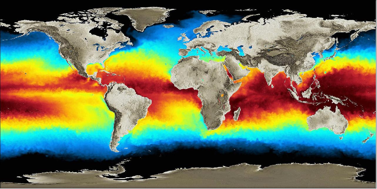
- Monitoring oceans: One of the most important objectives of the ERS missions was to deliver data for ocean research. The onboard radiometer provided information to map global sea-surface temperature very precisely. This led to novel observations of El Niňo and consequently helped scientists to understand more about this phenomenon and its links to global warming. In addition, the radar altimeter provided new information on sea-level change. The ERS mission also demonstrated their potential to provide data to detect oil spills and vessels at sea, monitor sea ice, forecast wind, waves and regional ocean currents, as well as map the sea floor.
- Tracking ice: Orbiting close to the poles, the ERS satellites captured one of Earth's most rapidly changing features: ice cover. Data from the ERS altimeters revealed how the height of the huge ice sheets covering Antarctica and Greenland is changing, as ice is lost to the ocean. Complementary radar imagery has been able to show exactly how fast the glaciers are advancing. The satellites also showed how the extent of sea ice in the Arctic Ocean varies seasonally and the general trend towards diminishing ice cover.
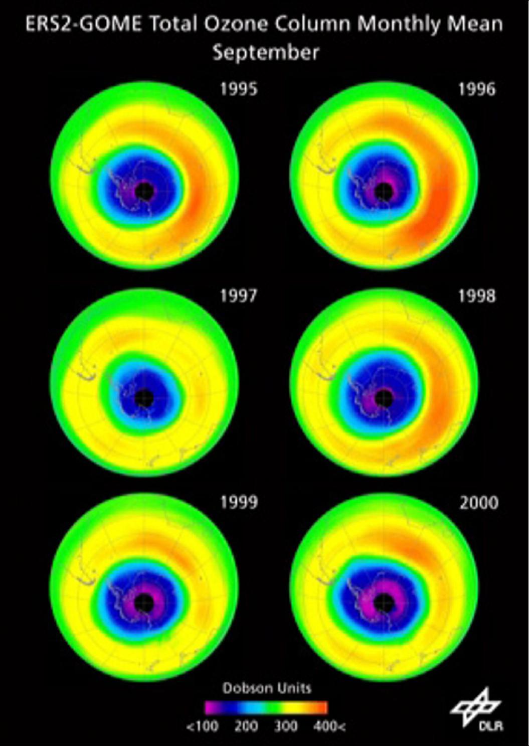
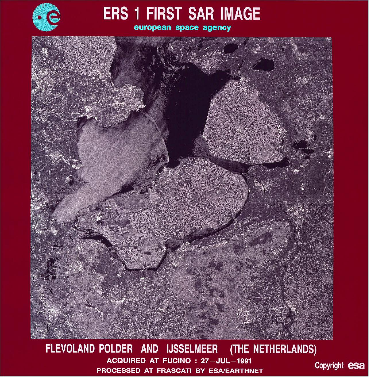
• July 15, 2021: A video interview was conducted with key figures Stephen Coulson (Former Earth Observation Applications Engineer), Mark Doherty (Former Head of ERS Product Control Service) and Henri Laur (Former Head of Processing of ERS-1 SAR data) to mark 30 years since the European Remote Sensing satellite (ERS-1), was launched into orbit on 17 July 1991. 9)
Sensor Complement
The total payload mass is 888.2 kg. The payload instruments are AMI, RA-1, ATSR (consisting of MWR and IRR), LRR, and PRARE. 10)
AMI (Active Microwave Instrument)
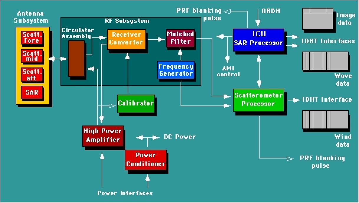
AMI is a SAR (Synthetic Aperture Radar) instrument, built by MMS (Matra Marconi Space), France. Two separate radars are incorporated within the AMI, a SAR for the "Image and Wave mode" operation, and a scatterometer (SCAT) for the "Wind mode" operation. This instrument can operate in either one of the following modes: 11)
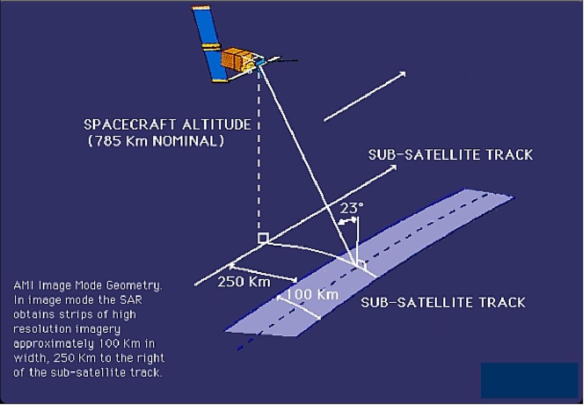
1) AMI in Imaging mode. Measurement in C-band (frequency = 5.3 GHz (equivalent to 5.66 cm wavelength), bandwidth = 15.55 MHz; polarization = Linear Vertical (LV); PRF range = 1640-1720 Hz in 2 Hz steps; long pulse = 37.12 µs; compressed pulse = 64 ns; peak power = 4.8 kW; antenna size =10 m x 1 m; look angle = 23º; radiometric resolution = 5 Bit on raw data (SAR mode), which corresponds to about 30 m spatial resolution; swath width = 100 km. Data rate = 105 Mbit/s.
Imaging mode operating time per orbit = 12 minutes ((12% duty cycle) including four minutes in eclipse). The SAR's high resolution in the range direction is achieved by phase coding the transmit pulse with a linear chirp and compressing the echo by matched filtering; range resolution is determined through the pulse travel time; the azimuth resolution is achieved by recording the phase as well as the amplitude of the echoes along the flight path.
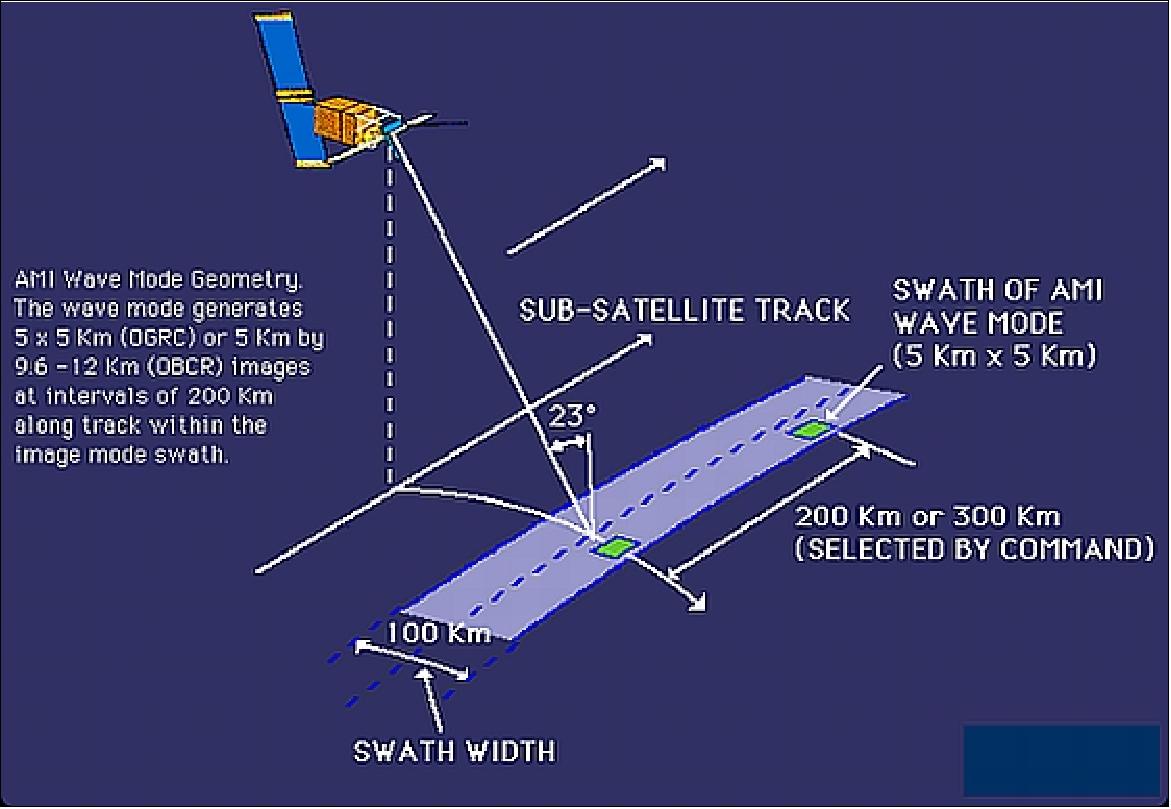
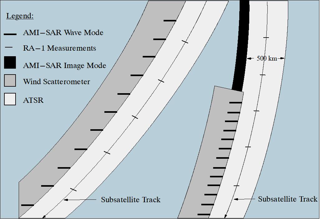
2) AMI in Wave Mode. Measurement of the changes in the radar reflectivity of the sea surface due to surface waves. Provision of images (5 km x 5 km), also referred to as "imagettes," at regular intervals of 200 km along the track. These "imagettes" are transformed into spectra providing information about the lengths and directions of the ocean wave systems. Characteristics: frequency = 5.3 GHz, polarization = Linear Vertical (LV); incidence (look) angle = 23º; wave direction: 0 - 180º.; wavelength = 100-1000 m; direction accuracy = ±20º; length accuracy =±25%; spatial sampling: 5 km x 5 km every 200-300 km; resolution = 30 m; data rate = 370 kbit/s; duty cycle of 70 %.
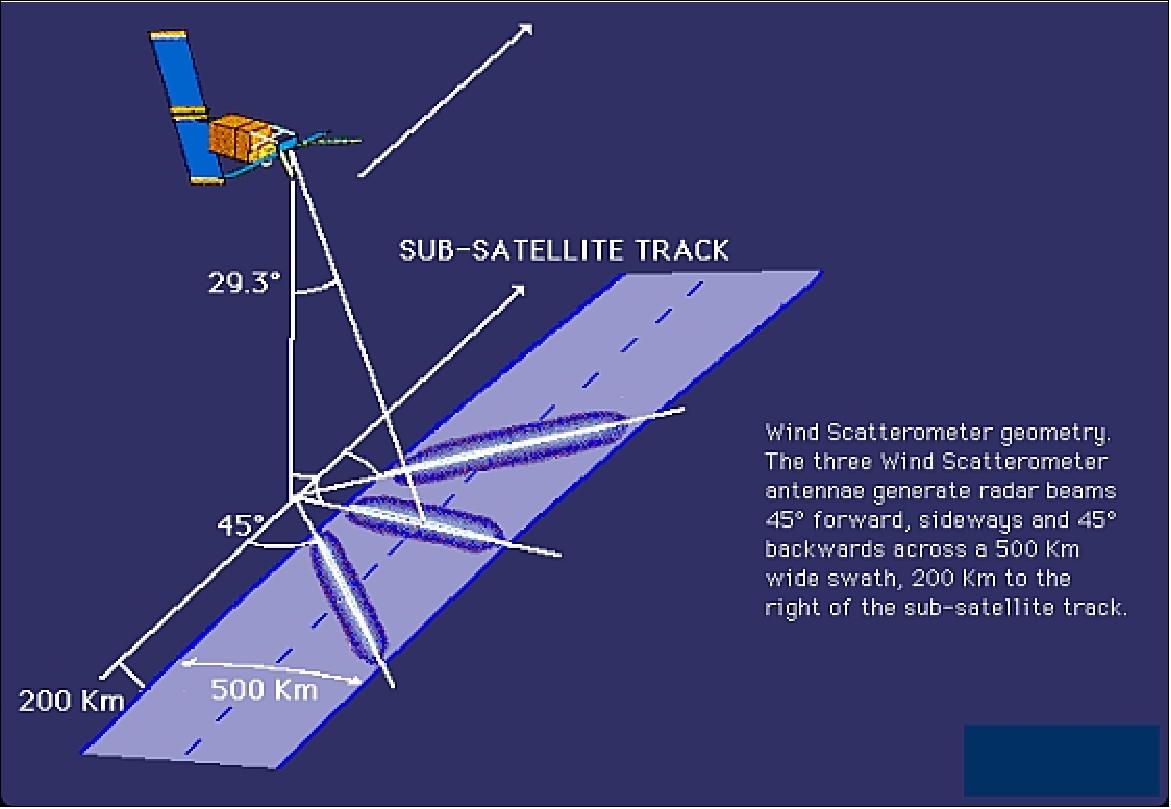
3) AMI in Wind Scatterometer Mode (AMI-SCAT). Use of three separate sideways-looking antennas (fore, mid and aft beams, see Figure 17) to measure sea surface wind speed and direction. Characteristics: wind direction range = 0 - 360º; accuracy = ±20º; wind speed range = 4-24 m/s; accuracy = 2m/s or 10%, spatial resolution = 50 km; grid spacing = 25 km; swath width = 500 km (same side as SAR imaging); swath stand-off = 200 km to side of orbital track; frequency = 5.3 GHz ±200 kHz; polarization = LV; peak power = 4.8 kW; incidence angle range = 16-42º (mid), 22-50º (fore), 22-50º (aft); antenna length = 2.3 m (mid), 3.6 m(fore), 3.6 m (aft); data rate = 500 kbit/s. Operation over all oceans.
Note: AMI-SCAT cannot be operated in parallel with the AMI SAR imaging mode; however, parallel operation of the wind and wave modes is possible. 12)
The three antenna beams continuously illuminate a swath of 500 km each measuring the radar backscatter from the sea surface for overlapping 50 km resolution cells using 25 km grid spacing. The result is three independent backscatter measurements relating to cell center nodes on a 25 km grid (three different viewing directions, separated by a very small time delay). This permits surface wind vector determination using "triplets" within the mathematical model.
AMI is an instrument providing data for a wide range of research disciplines such as:
- climatology,
- oceanography,
- glaciology,
- land processes,
- operational meteorology.
Operational mode | Band | Center | Polarization | Incidence angle | Spatial | Swath width |
SAR Imaging mode | C-band | 5.3 GHz | LV (linear vertical) | 23º at mid-swath | 10-30 m | 100 km |
SAR Wave | C-band | 5.3 GHz | LV | 23º +0.5º | 30 m | 5 km x 5 km |
AMI-SCAT (wind) | C-band | 5.3 GHz | LV | Fore/aft: 25º-29º | 50 km | 500 km |
Instrument specifications | |
SAR antenna size, look angle | 10 m x 1 m, 23º |
Long pulse, compressed pulse | 37.12 µs, 64 ns |
Peak power | 4.8 kW |
PRF (Pulse Repetition Frequency) | 1640-1720 Hz |
LOS (Local Oscillator Signal) | 5176 to 7442 MHz |
Radiometric specifications | |
Instrument center frequency | 5.3 GHz (5.6 cm wavelength), C-band |
Bandwidth | 15.55±0.1 MHz |
Polarization | VV |
Peak sidelobe ratio | along-track >20 dB; cross-track >18 dB |
Spurious sidelobe ratio | cross-track >25 dB, along-track >25 dB |
Ambiguity ratio | along-track >20 dB, cross-track >31 dB |
Radiometric resolution; | ≤2.5 dB at sigma zero (σο) = -18 dB |
Dynamic range | > 21 dB |
Radiometric stability; | ≤×0.95 dB |
Cross polarization (1-way) | > 15 dB |
Geometric specifications | |
Spatial resolution | along-track ≤ 30 m, cross-track ≤ 26.3 m |
Swath width | 102.5 km (telemetered), 80.4 km (full performance) |
Pointing accuracy | along-track ≤ 1 km; cross-track ≤ 0.9 km |
Incidence angle | near swath 20.1º. mid swath 23º. far swath 25.9º |
Incidence angle tolerance | < 0.5º |
Data quantization in imaging mode | OGRC (On-Ground Range Compression) mode: 5 bit I, 5 bit Q |
Operational specifications | |
Require ground station visibility / maximum operation time | < 12 minutes per orbit in total (duty cycle) |
Maximum on/off switch | 6 per orbit |
Wave mode specifications (same as AMI SAR except for the following parameters) | |
Swath width | Between 9.6 km and 12 km in OBRC (Onboard Range Compression) mode depending on position, |
Swath position of wave mode | Programmable anywhere within the SAR imaging swath |
Data quantization of wave mode | 4 bit I, 4 bit Q, in OBRC mode; 2 bit I, 2 bit Q, in OGRC mode |
Spatial resolution of wave mode | along-track ≤ 30 m; cross-track ≤ 26.3 m |
Peak sidelobe ratio | along-track ≥ 20 dB; across-track ≥ 18 dB |
Pointing accuracy | along-track ≤ 2 km; across-track ≤ 1.8 km |
AMI instrument mass | 325.8 kg |
RA-1 (Radar Altimeter-1)
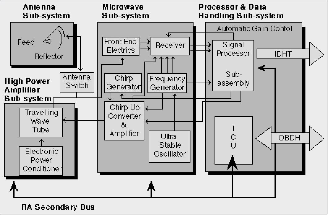
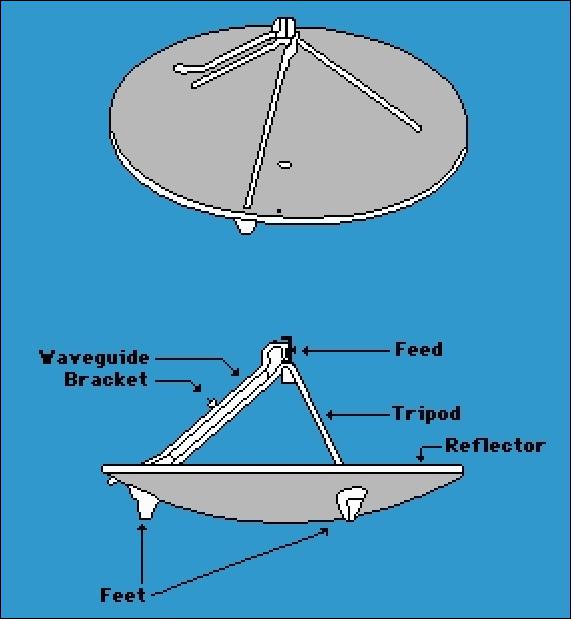
RA-1 is operating in Ku-band, consisting of a reflector, waveguide feed, tripod plus supporting structure, horn feed and the waveguide (built by Alenia Spazio, Italy). RA-1 is a nadir-pointing pulse radar taking precise measurements of the echos from the ocean and ice surfaces. Frequency = 13.8 GHz; pulse length = 20 μs; pulse repetition frequency = 1020 Hz; chirp bandwidth = 330 MHz (for ocean mode) and 82.5 MHz (for ice mode); RF transmit power = 55 W peak; antenna diameter = 1.2 m; max. data rate = 15 kbit/s; instrument mass = 96 kg; power = 130 W. 13) 14) 15)
RA-1 operates in 2 modes: ocean mode and ice mode. Beam width = 1.3º; foot print = 16 - 20 m (depending on sea state). RA-1 operates by timing the two-way delay for a short-duration radio frequency pulse, transmitted vertically downwards. The required level of range measurement accuracy (better than 10 cm) calls for a pulse compression technique (chirp). The instrument employs frequency modulation and spectrum analysis of the pulse shape.
RA-1 provides measurements leading to the determination of:
- Precise altitude (ocean surface elevation for the study of ocean currents, the tides and the global geoid)
- Significant wave height
- Ocean surface wind speed
- Various ice parameters (surface topography, ice types, sea/ice boundaries)
Antenna dish diameter | 1.2 m |
RF frequency | 13.8 GHz (Ku-band) |
Bandwidth: |
|
PRF (Pulse Repetition Frequency) | 1020 Hz |
RF transmit power | 50 W |
Pulse length | 20 µs chirp |
Beam width | 1.3º |
Foot print size | 16 to 20 km (depending on sea state) |
Backscatter coefficient | 0.7 dB (1s) |
Echo waveform samples | 64 bit x 16 bit at 20 Hz |
Altitude measurement | 10 cm (1s, SWH = 16 m) |
Instrument mass, power, data rate | 96 kg, ≤ 134.5 W, ≤ 15 kbit/s |
ATSR-1 (Along-Track Scanning Radiometer and Microwave Sounder-1)
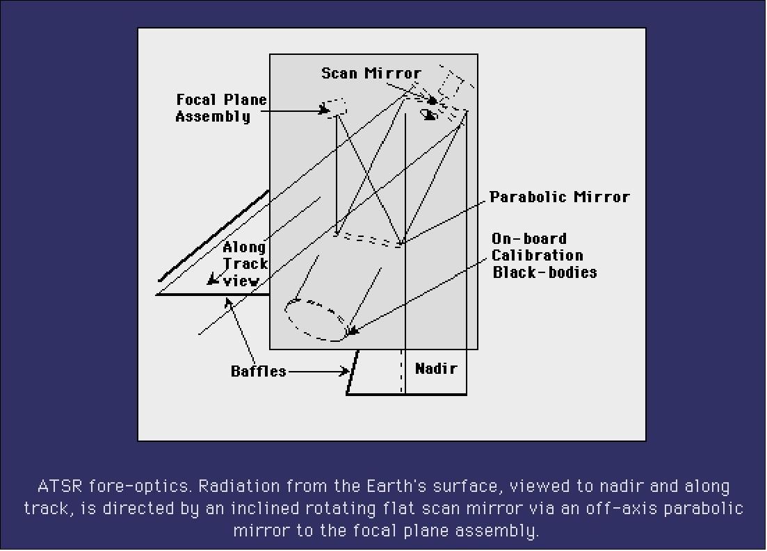
ATSR was developed and built by RAL, UK (British Aerospace as prime contractor); CRPE, France, and CSIRO, Australia. It consists of two instruments: the MWR (Microwave Radiometer) and the IRR (Infrared Radiometer). A major objective of ATSR is to measure the global SST (Sea Surface Temperature) with the high accuracy required by the climate change research community. The instrument design employs the use of low-noise infrared detectors, cooled to < 95 K by a Stirling cycle mechanical cooler.
• ATSR/MWR (Microwave Radiometer) characteristics: The MWR instrument uses a 60 cm Cassegrain offset-fed antenna to view the Earth in nadir direction in the frequencies of 23.8 and 36.5 GHz. The signals received are compared with those from a reference source at a known temperature to minimize the effects of short-term variations. Additional features are used to calibrate MWR: the sky-horn antenna is pointed toward cold space; the hot reference is obtained internally. IFOV = 20 km (= resolution); each channel has a bandwidth of 400 MHz.
The prime objective of MWR is measurements of atmospheric water-vapor and liquid content to improve the accuracy of the sea surface temperature measurements and also to provide accurate tropospheric range correction for the RA-1.
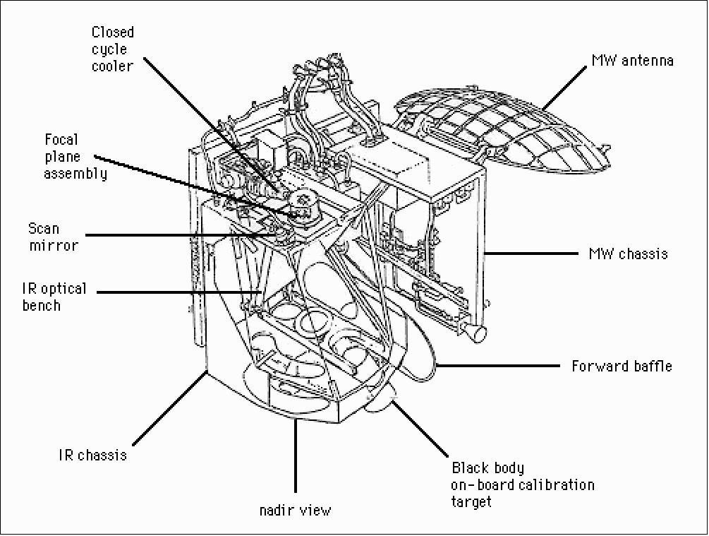
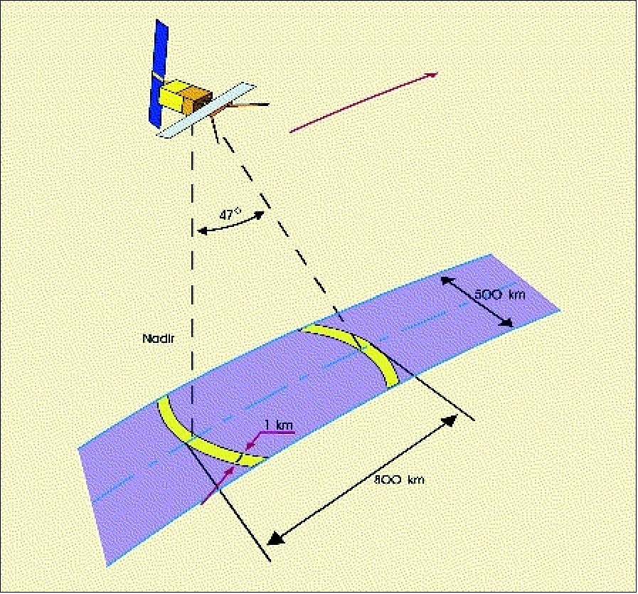
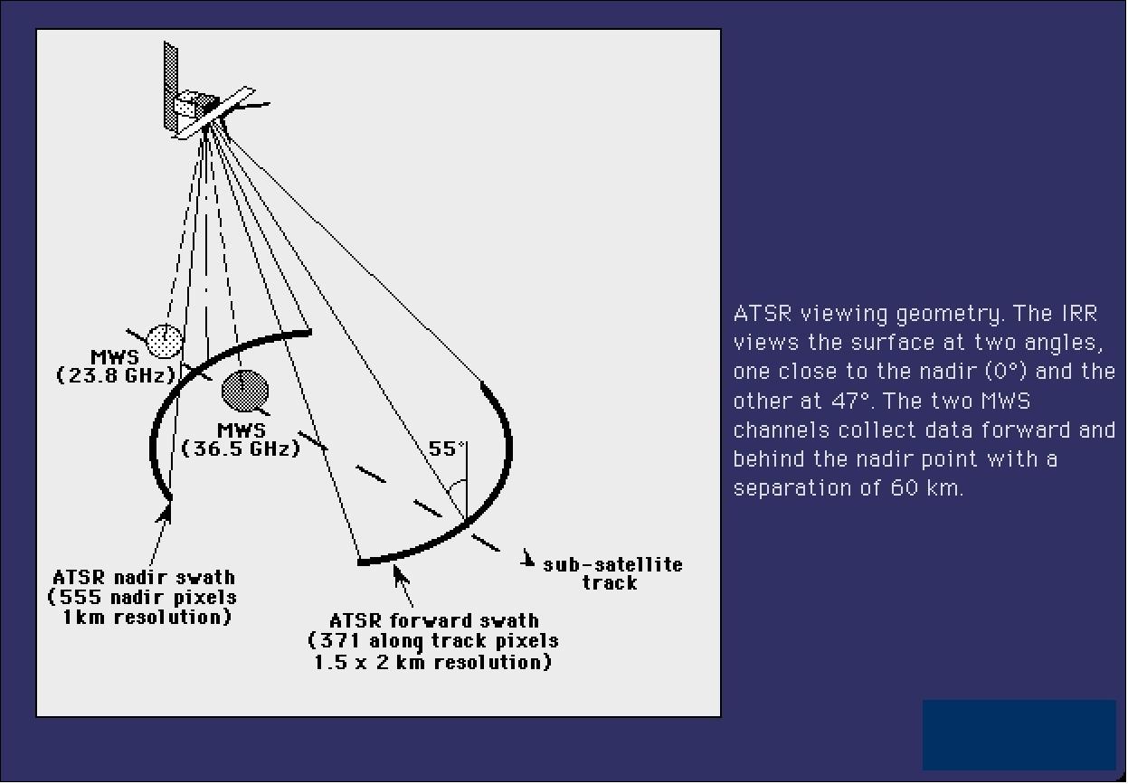
• ATSR/IRR (Infrared Radiometer) characteristics: The IRR imager has 4 spectral bands centered at: 1.6 µm, 3.7 µm, 10.8 µm and 12 µm. Spatial resolution = 1 km x 1 km (IFOV at nadir). Radiometric resolution < 0.1 K. Absolute accuracy < 0.5 K by averaging over a 50 km x 50 km area for SST with 80 % cloud cover; radiometric resolution <0.1 K; swath width = 500 km. The conical scanning technique enables the Earth's surface to be viewed at two different angles (0º and 47º) in two curved swaths 500 km wide and separated, along track, by about 800 km. Successive scans in the cross-track direction are displaced by about 1 km (along-track) due to the satellite's motion. A rotating mirror scans the two tracks once every 150 s (total of 2000 pixels per scan, 555 for nadir-view data and 371 for forward-view data)
Measurements of: 16) 17) 18) 19) 20)
- cloud-top temperature and cloud cover
- SST (Sea Surface Temperature), prime objective of IRR (accuracy achieved of ±0.3º).
The thermal channels of IRR use an advanced detector cooling system and can be calibrated (two blackbody references are being used during each scan). The IRR instrument features a conical scanning configuration resulting in a dual-view observation of the same target area. The sensor records a line of off-nadir pixels at a view zenith angle of about 55º and some 900 km along the track. About 2.5 minutes later, a nadir view is obtained when the S/C is directly over the target. The resultant image data set (after resampling both the nadir and forward view data) consists of two co-registered images with a 1 km spatial resolution on a 500 km swath. The dual-view design of ATSR makes it possible to estimate and correct for these atmospheric effects.
Observation objective | Center | Bandwidth | ATSR-1 | ATSR-2 | Detector type |
Chlorophyll | 0.55 µm | 20 nm | NA (Not available) | Yes | Si |
Vegetation index | 0.67 µm | 20 nm | NA | Yes | Si |
Vegetation index | 0.87 µm | 20 nm | NA | Yes | Si |
Cloud clearing | 1.6 µm | 0.3 µm | Yes | Yes | PV InSb |
SST retrieval | 3.7 µm | 0.3 µm | Yes | Yes | PV InSb |
SST retrieval | 10.8 µm | 1.0 µm | Yes | Yes | PC CMT |
SST retrieval | 12.0 µm | 1.0 µm | Yes | Yes | PC CMT |
LRR (Laser Retro-Reflector)
LRR is a passive optical device (corner cube reflectors) for accurate satellite tracking from the ground (laser ranging stations of the SLR network) to support instrument data evaluation. LRR characteristics: wavelength = 350 - 800 nm (optimized for 532 nm), efficiency: > 0.15 at end-of-life, reflection coefficient: > 0.8 end-of-life, FOV: elevation half-cone angle = 60º, azimuth of 360º, diameter: ≤ 20 cm.
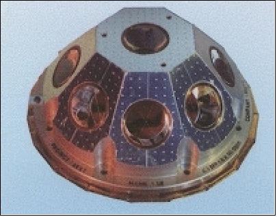
The corner cubes are made of the highest-quality fused silica and work in the visible spectrum. Their performance is optimized at the two wavelengths (694 nm and 532 nm) commonly used in SLR stations. The corner cubes are symmetrically-mounted on a hemispherical surface with one nadir-pointing corner cube in the centre, surrounded by an angled ring of eight corner cubes. 21)
PRARE (Precise Range And Range-Rate Equipment)
The PRARE objective is precise satellite range determination leading to higher-accuracy altitude measurements. PRARE utilizes 2.2 GHz and 8.5 GHz transmissions for ionospheric corrections and orbit determination, respectively. This information is needed for ocean circulation studies and geodetic applications such as sea-surface topography and crustal dynamics.
Note: The onboard PRARE instrument of the ERS-1 payload could not achieve operational status after launch. The instrument worked nominally for five days after launch (five contacts with the command station showed nominal telemetry). A thorough failure analysis concluded that the most likely cause of the PRARE failure is RAM damage due to radiation (destructive RAM latch-up).
The description of PRARE is part of the ERS-2 documentation.
ERS Data Transmission and Ground Segment
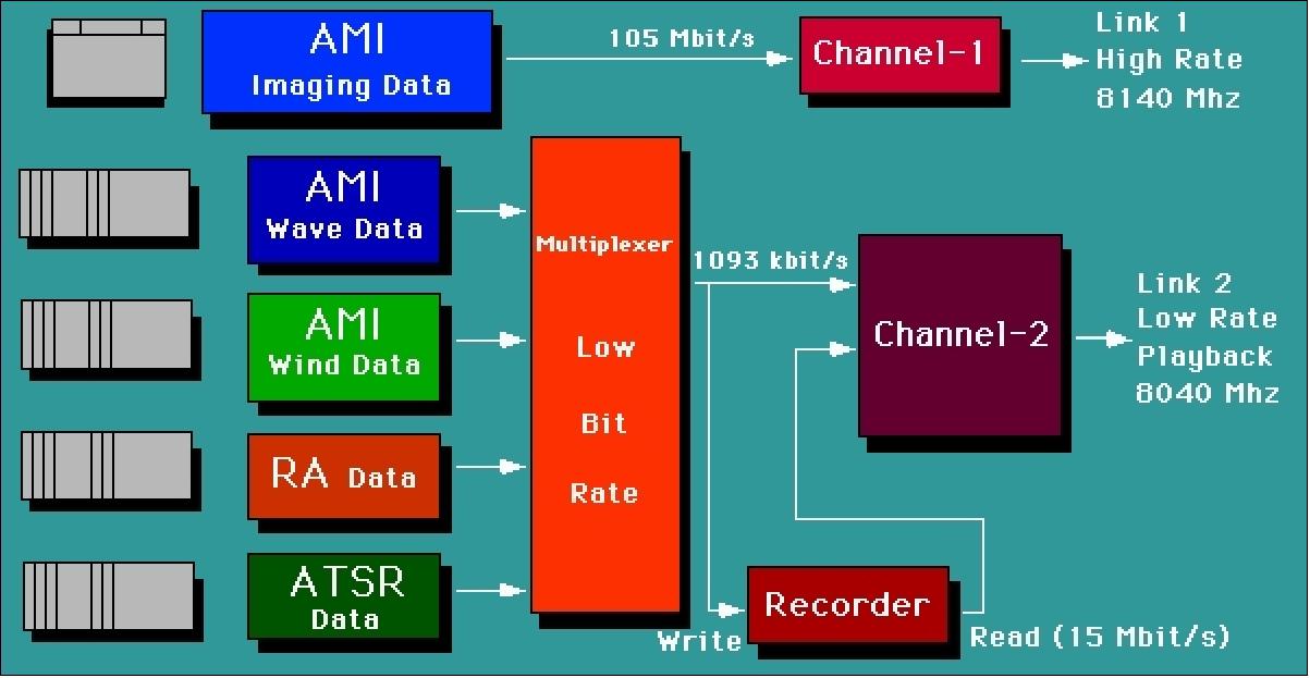
The payload data are transmitted by the IDHT (Instrument Data Handling and Transmission) subsystem. The instruments generate data in the form of source packets which in turn are put into transport frames for transmission.
Three data streams are transmitted from the IDHT in X-band:
- Link 1 contains high-rate real-time SAR data at a rate of 105 Mbit/s (8140 MHz);
- Link 2 contains low-rate real-time data (AMI wave and wind data, RA-1 and ATSR data) at a rate of 1.093 Mbit/s (8040 MHz);
- Link 3 contains recorder data (all of Link 2) at a rate of 15 Mbit/s.
Link 1 is dedicated onto one X-band link, while Link 2 and 3 share the second X-band link. The modulation scheme for Links 1 is QPSK (Quadrature Phase-Shift Keying). The low-rate link uses UQPSK (Unbalanced Quadrature Phase-Shift Keying) to modulate Link 2 and Link 3 data onto a single link. With no recorder dump data BPSK (Bi-Phase-Shift Keying) is used for the real-time data.
The ERS-1 onboard data recorder (magnetic tape recorder) had a capacity of 6.5 Gbit, equivalent to the LBR data volume acquired in one orbit. Although the recorder capacity was exceptionally large for its time of implementation (1990), the AMI SAR data rate of 105 MBit/s could not be recorded, only a real-time downlink service provision was possible. Data from the tape recorder were downlinked at 15 Mbit/s.
Packetized communications protocol. The ERS-1 spacecraft is the first project anywhere introducing the newly defined communication protocols of CCSDS (Consultative Committee for Space Data Standards), a recommendation for all data formats and transmission protocols to support a range of functional services. In the meantime, these protocol recommendations have become a "way of life" and standards for virtually all successive Earth observation missions as well as for many commercial communication missions. A definite advantage of the standard is the provision for interoperability with stations/segments of other space agencies.
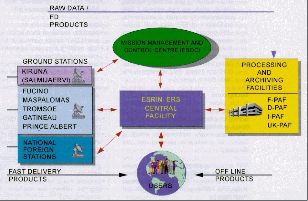
The ERS Ground Segment includes facilities for the satellite's control and operation, for reception, archiving and processing of the instrument data and provides services to satisfy user requirements for products.
It consists of the following elements: 22) 23) 24) 25) 26) 27)
• EECF (Earthnet ERS-1 Central Facility) in Frascati, Italy (ESA/ESRIN), carries out all user interface functions, including cataloging, handling of user requests, payload operation planning, scheduling of data processing and dissemination, quality control of data products and system performance monitoring.
• MMCC (Mission Management and Control Center) in Darmstadt, Germany (ESA/ESOC). MMCC carries out all satellite operations control and functional management, including overall satellite and payload operational scheduling. It also controls the Kiruna ground station.
• Ground stations: 28)
- The ESA ground stations at Kiruna, Fucino (Italy), Maspalomas (Canary Islands, Spain), and Gatineau (Canada);
- National ground station facilities, like the Canadian "Prince Albert" station, the DLR/DFD "O'Higgins" station (in Antarctica) as well as a portable station which can be set up anywhere (DTXS = DFD Transportable X-band Station), the CNES Aussaguel station, the Japanese stations "Hatoyama," "Kumamoto" and "Syowa" (Antarctica), the Indian (ISRO) station Hyderabad, the Alaska SAR Facility, Fairbanks (NASA), Alice Springs and Hobart (Australia), Tromsö (Norway), Cuiaba (Brazil, INPE), Cotopaxi (Ecuador), Miyun (China, CAS), Ryadh (Saudi Arabia), Bangkok (Thailand), Pretoria (South Africa, CSIR), Chung-li, Taoyuan (Taiwan), West Freugh (Scotland, BNSC), Tel Aviv (Israel, ISA), Parepare (Indonesia, LAPAN), Islamabad (Pakistan), Norman (Oklahoma, Eosat), Singapore (University of Singapore), etc.
Ground stations are equipped with "Fast Delivery" SAR processors, capable of generating quicklook images after reception of the pass. These "Fast Delivery Products" (FDP) are directly mailed to the national PAF's (Processing and Archiving Facility).
• Processing and Archiving Facilities (PAFs)
- D-PAF at DLR/DFD in Oberpfaffenhofen, Germany
- F-PAF at CERSAT, Brest, France
- I-PAF at ASI, Matera, Italy
- UK-PAF at RAE, Farnborough, UK
• User centers and individuals, such as national and international meteorological services, oceanographic institutes, various research centers and individual users.
The inability of ERS-1 onboard SAR data recording in the early 1990s created in addition new infrastructures in the form of mobile and stationary ground receiving stations at various sites around the globe.
The reason: despite many participating receiving stations (that were gradually added during the ERS program), there was no global coverage for real-time-only reception of SAR data (repetitive observational data of the region of interest). Some remote sites, like Antarctica, were considered to be of great interest by the science community. Other sites (continents), like most of Africa, inner Asia, and portions of South America, were simply lacking a high-volume, data-receiving infrastructure.
Hence, mobile station services were gradually introduced to complement the ERS ground station network.
Some of these mobile (or stationary) receiving stations are:
- GARS (German Antarctic Receiving Station O'Higgins) is a SAR data acquisition station, located at the site of the Chilean Base General Bernardo O'Higgins (Antarctic Peninsula), it was founded in 1989. O'Higgins is located at 57.90º W longitude and 63.32º southern latitude. GARS was installed by DLR/DFD in the southern summer of 1990/91 and is owned by DLR. GARS features an antenna of 9 m diameter and is capable of supporting several projects.
- Syowa Station on Antarctica (Japan, NASDA/NIPR), located at 39.58º E longitude and 69.00º southern latitude.
- Libreville, Gabon (DLR)
- Ulan Bator, Mongolia (DLR)
- McMurdo station at Hut Point Peninsula on Ross Island, Antarctica (NASA/ASF (Alaska SAR Facility), since 1956), located at 166.67º E longitude, and 77.85º southern latitude.
All of these stations are capable of downlinking the recording of SAR image data (of various missions, ERS-1, JERS-1, RADARSAT, ERS-2, Envisat, etc.). The more recent missions (RADARSAT, Envisat) have onboard recorders permitting at least a limited amount of SAR image data recording.
Commercial ERS Data Distributors
In 1992 ESA selected the first three distributors for ERS-1 data products. These are 29):
- Radarsat International of Ottawa, Canada (responsible for commercial sales in Canada and the USA)
- EURIMAGE of Rome, Italy (markets in Europe, North Africa, and the Middle East)
- SPOT Image of Toulouse, France (rest of the world).
References
1) G. Duchossois, "The ERS-1 Mission Objectives," ESA Bulletin No 65 Feb. 1991, pp. 16-26
2) R. Francis, et al., "The ERS-1 Spacecraft and its Payload," ESA Bulletin No 65 Feb. 1991, pp. 27-48
3) http://earth.esa.int/ers/satconc/
4) D. Andrews, S. J. Dodsworth, M. H. McKay, "The Control and Monitoring of ERS-1," ESA Bulletin No 65 Feb. 1991, pp. 73-79
5) H. Ege, "Industrial Cooperation on ERS-1," ESA Bulletin No 65 Feb. 1991, pp. 88-94
6) E. Attema, R. Francis, "ERS-1 Calibration and Validation," ESA Bulletin No 65 Feb. 1991, pp. 80- 87
7) "Father of ERS wins Nobel prize in physics," ESA Applications, 7 October 2021, URL:
https://www.esa.int/Applications/Observing_the_Earth/
Father_of_ERS_wins_Nobel_prize_in_physics
8) "ERS: 30 years of outstanding achievements," ESA Applications, 16 July 2021, URL:
https://www.esa.int/Applications/Observing_the_Earth/
ERS_30_years_of_outstanding_achievements
9) "ERS-1: the first image," ESA Applications, 15 July 2021, URL: https://www.esa.int/ESA_Multimedia/Videos/2021/07/ERS-1_the_first_image
10) "ERS-1 Payload Summary," 1992, URL: http://ceos.cnes.fr:8100/cdrom-97/ceos1/satellit/ers/paysum.htm
11) E. P. W. Attema, "The Active Microwave Instrument On-Board the ERS-1 Satellite," Proceedings of IEEE, Vol. 79, No.6, June 1991, pp. 791- 799
12) ERS-1 User Handbook, ESA SP-1148, May 1992, pp. 6-7
13) G. Schreier, K. Maeda, B. Guindon, "Three Spaceborne SAR Sensors: ERS-1, JERS-1, and RADARSAT- Competition or Synergism?," Geo Informationssysteme, Heft 2/1991, Wichmann Verlag, Karlsruhe, pp. 20 - 27
14) R. Winter, D. Kosmann "Anwendungen von SAR-Daten des ERS-1 zur Landnutzung," Die Geowissenschaften, 9. Jahrgang, Heft 4-5, April-Mai 1991, pp. 128-132
15) W. Kühbauch, "Anwendung der Radarfernerkundung in der Landwirtschaft," Die Geowissenschaften, 9. Jahrgang, Heft 4-5, April-Mai 1991, pp. 122-127
16) T. Edwards, R. Browning, J. Delderfield, D. J. Lee, K. A. Lidiard, R. S. Milborrow, P. H. McPherson, et al., "The Along Track Scanning Radiometer measurement of sea-surface temperature from ERS-1," Journal of the British Interplanetary Society, Vol. 43, 1990, pp.160-180.
17) F. M. Danson, N. A. Higgins, N. M. Trodd, "Measuring Land-Surface Directional Reflectance with the Along-Track Scanning Radiometer," PE&RS, Vol 65, No 12, Dec. 1999, pp. 1411-1417
18) http://www.atsr.rl.ac.uk/documentation/docs/userguide/index.shtml#MARKER-9-11
19) N. C. M. Stricker, A. Hahne, D. L. Smith, J. Delderfield, M. B. Oliver, T. Edwards, "ATSR-2: The Evolution in Its Design from ERS-1 to ERS-2," ESA Bulletin No 83, Aug. 1995
20) http://earth.esa.int/rootcollection/eeo4.10075/ERS1.5.html
21) http://earth.esa.int/brat/html/missions/ers1/instruments/lrr_en.html
22) M. Fea, "The ERS-1 Ground Segment," ESA Bulletin No 65 Feb. 1991, pp. 49-59
23) http://earth.esa.int/ers/eeo3.324/
24) W. Markwitz, "Das ERS-1 Bodensegment, Empfang, Verarbeitung und Archivierung von SAR Daten," Die Geowissenschaften, 9. Jahrgang, Heft 4-5, April-Mai 1991, pp. 111-115
25) D. Gottschalk, "ERS-1 Mission and System Overview," Die Geowissenschaften, 9. Jahrgang, Heft 4-5, April-Mai 1991, pp. 100-101
26) M.F. Buchroithner, J. Raggan, D. Strobl "Geokodierung und geometrische Qualitätskontrolle," Die Geowissenschaften, 9. Jahrgang, Heft 4-5, April-Mai 1991, pp. 116-112
27) S. D'Elia, S. Jutz, "SAR Mission Planning for ERS-1 and ERS-2," ESA Bulletin, No 90, May 1997
28) J-C. Bigot, V. Beruti, "The National and Foreign Stations - Key Partners in the ERS Ground Segment," ESA Bulletin No 101, February 2000,
29) `ESA Signs Long-awaited Imagery Sales Deal,' Space News, Feb. 10-16, 1992, p. 4
Spacecraft Launch Mission Status Sensor Complement Ground Segment References Back to top