EURECA (European Retrievable Carrier)
EO
ESA
Atmosphere
Aerosols
Quick facts
Overview
| Mission type | EO |
| Agency | ESA |
| Mission status | Mission complete |
| Launch date | 31 Jul 1992 |
| End of life date | 02 Aug 1992 |
| Measurement domain | Atmosphere, Gravity and Magnetic Fields |
| Measurement category | Aerosols, Radiation budget, Gravity, Magnetic and Geodynamic measurements, Trace gases (excluding ozone) |
| CEOS EO Handbook | See EURECA (European Retrievable Carrier) summary |
Overview
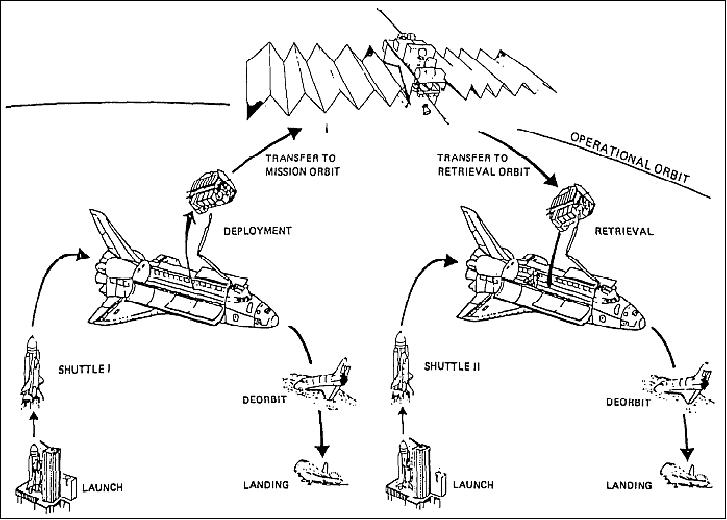
EURECA was an ESA space environment exploration mission designed and developed to be recovered from orbit after completion of the mission and returned to Earth. The main objective of the recovery mission was the post-flight study of environmental effects (meteoroids and space debris impact) and wear-out mechanisms to the spacecraft and its payload.
Spacecraft
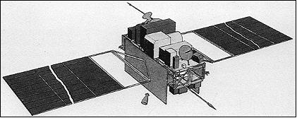
The EURECA spacecraft bus structure had dimensions of 4.6 m x 2.6 m. The bus structure consisted of carbon fiber struts connected by titanium nodal joints. A grapple fixture permitted deployment/retrieval by the Shuttle Remote Manipulator System (RMS). EURECA was three-axis stabilized by magnetorquers, supported by a reaction control assembly of 6 x 21 mN nitrogen thrusters. Orbit transfers between altitudes of 400-500 km were performed by the orbit transfer assembly of redundant 4 x 21 N hydrazine thrusters (the propellant volume was sized for two transfers and 9 months on-orbit stay). The attitude rate was measured by an accelerometer package, gyros and IR Earth and sun sensors. Power was provided by twin deployable/retractable panels of silicon solar cells, generating 1.5 kW at 28 VDC (providing 1 kW average for payload operations). In addition, 4 NiCd batteries provided energy of 40 Ah each.
The launch mass of EURECA was 4490 kg (payload capacity of up to 1000 kg). At the time, EURECA was the largest spacecraft so far built and flown by ESA. When deployed, EURECA measured 20 m across from wing tip to wing tip. 1) 2) 3) 4) 5)
Total spacecraft mass, payload mass | 4490 kg, 1000 kg |
Payload power | 1 kW average, 1.5 kW peak |
Orbit control | Earth pointing mode, hot gas system |
Attitude control | Hot or cold gas system |
Attitude sensing | Sun and Earth sensors, gyros, accelerometers |
Attitude: sun inertial pointing | ±1º (3σ), the actual performance during flight was ± 0.45º |
Attitude measurement accuracy | ±0.25º (3σ) |
Microgravity environment | < 10-5 g for f < 1 Hz linear for 1 Hz < f < 100 Hz |
Onboard data storage capacity | 13 MByte (11.3 for payload data, 1.7 for housekeeping data) |
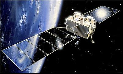
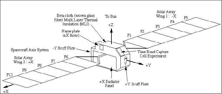
The external surface of the spacecraft was almost entirely covered by thermal Multi-Layer Insulation (MLI) blankets. The only exceptions were the radiators and some boxes mounted on the bottom of the spacecraft, which were painted, and the solar-array wings. The total area of the exposed external surface was about 140 m2, including 99 m2 of solar arrays (front and back surfaces), with a deployed span of 20 m tip-to-tip.
RF communications: Data was transmitted via S-band downlink at rates up to 256 kbit/s.
The mission's output was composed of space science and experiment data sent to the ground regularly for scientific and engineering analysis, materials processes in the environment of very low residual acceleration that was offered by the EURECA mission, sample exposure to the space environment, surface forces research, space particle collection and new technology applications. While a significant portion of the mission's yield was contained in its abundant and continuous data generation, the primary mission objective was the analysis in ground based laboratories of the biological and material-samples after their return to Earth and the ability, in principle, to the spacecraft and payloads again in a later flight. 6) 7)
Mission operations of EURECA-1 was provided by ESOC in Darmstadt; some payload operations were provided by MUSC (Microgravity User Support Center) of DLR in Cologne, Germany.
The spacecraft was developed and integrated at EADS (formerly DASA/ERNO), Bremen, Germany under ESA contract as a re-usable, multi-disciplinary platform for microgravity, science and technology missions. Its design life was based on at least five flights, each lasting from several months to nearly one year, and an on-ground turn-around time of maximum two years. - However, only a single mission was conducted with the EURECA spacecraft.
Bringing EURECA back to Earth following its first mission proved to be an invaluable contribution not only to payload and mission product owners, but also to technical areas dealing with in-orbit performance validation and, in particular, with the identification of the causes of in-orbit anomalies.
Launch
The launch of EURECA by Shuttle (Atlantis, STS-46, EURECA was part of the payload in the cargo bay) from KSC, Cape Canaveral, FLA, on July 31, 1992 (8 day mission).
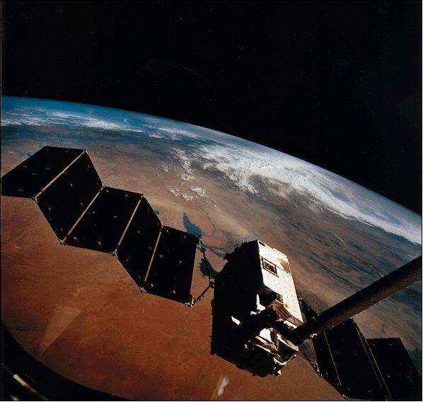
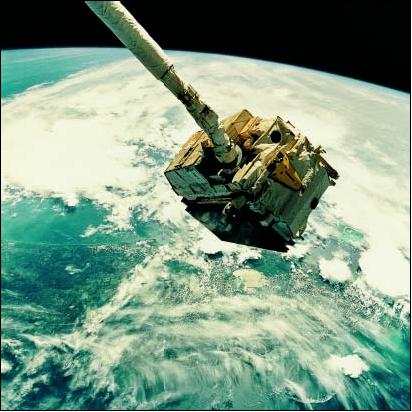
The EURECA payload was deployed from the Shuttle on Aug. 2, 1992 using the RMS (Remote Manipulator System). Then EURECA performed a burn raising its orbit from 420 km to an operational altitude of 508 km. It began its scientific mission on August 7, 1992.
Orbit: Low Earth Orbit (LEO) circular; altitude = 508 km, inclination = 28.45º, retrieval altitude of 476 km.
Mission Status
The retrieval of EURECA by Shuttle (Endeavour) during the STS-57 mission (June 21 - July 1, 1993) using the Shuttle's RMS , also referred to as Canadarm. EURECA spent 11 months (336 days) in a sun-pointing orbit.
Sensor Complement
The Eureca payload included a total of 16 active instruments/experiments (six for microgravity research, two for space radiation research, five for space science research, three for technology demonstrations) and a number of entirely passive payloads. - Only those sensors are described and indexed that fit into the scope of the book, namely: “Observation of the Earth and its Environment.” The other sensors (in the life and material sciences) are simply listed with a short commentary.
ERA (Exobiology and Radiation Assembly). A multiuser life science facility for experiments on the biological effects of space radiation. PI: H. Bücker, DLR, Germany. 8)
AMF (Automatic Mirror Furnace). Optical radiation furnace for growing single, uniform crystals from the liquid or vapor phases, using the travelling heater or Bridgman methods. PI: K. W. Benz, Universität Freiburg, Germany.
SGF (Solution Growth Facility). A multiuser facility for growing monocrystals from solution. PI: J. C. Legros, Université Libre de Bruxelles, Belgium.
PCF (Protein Crystallisation Facility). A multiuser solution growth facility for protein crystallisation in space. PI: W. Littke, Universität Freiburg, Germany.
MFA (Multi-Furnace Assembly). A multiuser facility dedicated to material science experiments. PI: A. Passerone, National Research Council, Genoa, Italy
HPT (High Precision Thermostat). An instrument for long-term experiments requiring microgravity conditions and high precision temperature measurement and control (typical experiments are: `caloric', `critical point', and `phase transitions'). PI: G. Findenegg, Ruhr Universität, Bochum, Germany.
SFA (Surface Forces Adhesion). Study of the dependence of surface forces and interface energies on physical and chemical-physical parameters such as surface topography, surface cleanliness, temperature, and the deformation properties of the contacting bodies. PI: G. Poletti, Università di Milano, Italy.
IOC (Inter-Orbit Communication Instrument)
A technological experiment to provide a pre-operational in-flight test and demonstration of all required instrument functions and services. PI: R. Tribes, CNES, France. The instrument utilized the 20/30 GHz band for transmission between the user satellite, ground station, and relay satellite. The ESA communications satellite, Olympus, was used as the relay satellite between EURECA and the ground station. 9)
Instrument mass, power consumption | 67 kg, 140 W (max) |
Nominal mounting area | 140 cm x 70 cm |
Tx frequency, Rx frequency | 28.622 GHz, 18.925 GHz |
EIRP | 39 dBW |
Polarization | Linear |
Data rates | TC 2 kbit/s in uplink |
Ranging | up to 100 kHz tone |
Antenna tracking | open loop (by command), or closed loop (automatic) |
During the EURECA 11 month mission, the IOC payload was configured in dormant mode for about 18 weeks. During the remaining time it was used for its commissioning, measurement and assessment of its 20/30 GHz Radio Frequency link behavior and quality, its exploitation in providing transmissions to users and its support to EURECA operations.
ASGA (Advanced Solar Gallium Arsenide Array)
ASGA was sponsored by ASI. A technological experiment for the performance testing of future solar arrays. PI: C. Flores, CISE SPA, Segrate, Italy. These solar cells (GaAs), already being used in a trial form to power the Soviet MIR space station, are expected to form the backbone of the next generation of compact, high power-to-weight ratio European solar energy generators. 10)
RITA (Radio-Frequency Ion Thruster Assembly)
Study of the use of ion electric propulsion in space. PI: H. Bassner, DASA-MBB, Munich, Germany. European research into radio-frequency ion propulsion was initially conducted in the 1960's by the University of Giessen, Germany. EADS's predecessor, MBB, then joined the development team in 1970 and undertook the industrial leadership. The first RITA instrument was successfully demonstrated in space aboard ESA's EURECA. At that time, the RIT-10 system aboard EURECA provided a nominal specific impulse of 3,058 seconds. It featured a beam diameter of 87 mm and provided flawless operation demonstrations of 240 hours in total. Measurements confirmed there was no EMC (Electromagnetic Compatibility) interference between the satellite, payload or electronics. 11) 12) 13)
WATCH (Wide Angle Telescope)
PI: N. Lund, Danish Space Research Institute, Lyngby, Denmark. Objective: detection of celestial gamma-ray burst sources and X-ray sources with photon energies in the range of 6 - 150 keV, measurement of source direction. The total field of view (FOV) covered 1/4 of the celestial sphere. WATCH gradually scanned across the entire sky during the 11 month mission.
WATCH is a wide-field monitor based on the `rotation modulation collimator' principle. It has a circular field of view with a radius of about 65º. There are two interleaved detectors which create a phoswich of alternating strips of NaI(Tl) and CsI(Na). Each strip is 5 mm wide by 2 mm thick. The diameter of the phoswich is 110 mm and it is viewed across a 10 mm air gap by a single 125 mm photomultiplier. The effective area of the NaI and CsI scintillators if about 45 cm2. The sensitivity is about 100 mCrab in one day. The effective observation time for the 318 day mission was 120 days. The minimum time resolution was 64 microseconds. 14) 15)
A total of 19 cosmic GBR (Gamma-Ray Bursts) were detected by the WATCH X-ray monitor during the 11 months flight of EURECA.
TICCE (Timeband Capture Cell Experiment)
Study of microparticle population distributions in near-Earth space, typically Earth debris, meteoroids, and cosmic dust. TICCE captures micron-dimensional particles with velocities in excess of 3 km/s and stores the debris for retrieval and post-mission analysis. PI: J. A. M. McDonnell, University of Kent, UK.
Particles detected by the instrument pass through a front foil and into a debris collection substrate positioned 100 nm behind the foil. Each perforation in the foil has a corresponding debris site on the substrate. The foil is moved during the mission in 50 discrete steps. The phase shift between the debris site and the perforation enables a determination of the impact time. Instrument mass = 8 kg, dimensions: 690 x 690 x 80 mm.
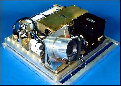
ORA (Occultation Radiometer Instrument)
Objective: measurement of aerosols and trace gas densities in the Earth's mesosphere and stratosphere (vertical profiles between 20 - 100 km of: ozone, nitrogen dioxide, water vapor, carbon dioxide, and background and volcanic aerosols) . PI: E. Arijs, BIRA (Belgisch Instituut voor Ruimte Aeronomie), Brussels, Belgium. 16) 17)
ORA measures the intensity of solar radiation during the sunrise and sunset phases of each orbit. It uses the sun pointing capabilities of EURECA and makes measurements in ten narrow wavelength bands (UV/VIS, NIR) in the spectral region 250 - 1100 nm. ORA consists of a UV/VIS unit, an NIR unit and a control/electronics unit. The UV/VIS unit has 8 similar modules which measure the relative solar irradiance in narrow bands. Each module contains a quartz window, an interference window to select the appropriate wavelength, optics to limit the detector viewing angle, and a photodiode.
The ORA instrument was mounted on the “science panel” of the carrier. It consists of a mechanical structure containing the UV-visible module (for the measurement of 03, NO2, H20 and aerosols in the stratosphere), the infrared unit (for the measurement of water in the mesosphere) and an electronics unit (for instrument control and interface with the satellite data handling system). EURECA being designed for micro gravity, moving parts in the instrument had to be limited to a minimum. Therefore, in view of the weight and power budget and considering that the carrier is sun pointing by itself, the ORA instrument has no sun tracking device. Instead, the field of view of the optical modules was chosen to be large enough to assure a full view of the sun.
SOVA (Solar Variability Experiment)
SOVA is a radiometer, a copy of SOLCON. Objective: measurement of the solar constant, its variability and its spectral distribution. PIs: D. Crommelynck, IRMB, Brussels, Belgium; C. Fröhlich, PMOD/WRC Davos, Switzerland. 18) 19)
The instrument is composed of three boxes, two of which (SOVA1 and SOVA2) house the various devices dedicated to functions such as sun-pointing, sun photometers, and two different types of absolute radiometers. The absolute radiometers are very accurate instruments for the measurement of total irradiance. They are essentially cavities, in which the solar radiation is trapped and absorbed. Heat flux transducers convert the radiative power into electrical power and return a calibrated measurement of the sun's radiation. The high precision radiometer (RELOS) is used to measure solar oscillations in total irradiance. The sun-pointing resolution of SOVA2 is 2 arc seconds. The sun photometers use interference filters to select the wavelength band and silicon diode devices to measure the radiation. The complete set of photometers covers the spectrum from 303 nm to 865 nm. 20) 21)
SOSP (Solar Spectrum Instrument)
Objective: study of solar physics and solar-terrestrial relationships in aeronomy and climatology. Measurement of absolute solar irradiance and its variations in the spectral range 170 - 3200 nm (accuracy of 1% in VIS/IR and 5% in UV). PI: G. Thullier, CNRS, Verriers le Buisson, France. 22)
SOSP has three spectrometers, one for each spectral domain (UV/VIS/IR). The spectrometers select the spectral range using a double monochromator; irradiance measurement with a photomultiplier in UV and VIS, in IR with a cooled lead sulfide cell. Spectral resolution: 1 nm in UV/VIS, 20 nm in IR. In-flight calibration is provided.
Inspection of Retrieved Spacecraft
The retrieval of EURECA has given ESA a rare opportunity to study the fluxes and resulting effects of meteoroid and space-debris impacts on exposed spacecraft surfaces in LEO (Low Earth Orbit). With its fixed sun-pointing attitude, large areas of identical surface materials, and 1992-1993 exposure period, EURECA has provided impact data that are complementary to those from LDEF (Long Duration Exposure Facility) of NASA. Note: LDEF was deployed on April 7, 1984 on Shuttle flight STS-41C. LDEF was recovered 69 months after launch on January 12, 1990 (STS-32).
After the return of the Shuttle to KSC (Kennedy Space Center) on July 1, 1993, the EURECA spacecraft received a full inspection of the platform's upper surface in the Orbiter Processing Facility. The general impression was that there had been a significant change in the colors of the exposed surfaces, where outgassing products had been deposited on the thermal blankets. Areas of paint de-lamination and many micro-meteoroid impacts were clearly visible. 23) 24)
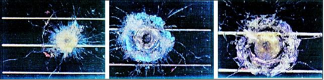
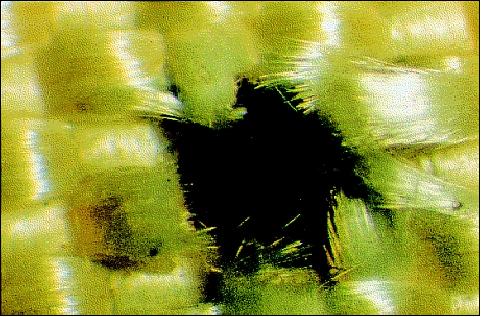
Later on, a wide-ranging set of investigations was undertaken to identify and characterize all impact features on the surfaces. Many groups participated in these investigations. The impact features were used to deduce properties of the impacting population and thereby to contribute to the validation of space debris and meteoroid environment and damage models. MLI thermal blankets, solar cells and other surfaces were examined and the investigations included residue analysis.
The main findings of the detailed visual survey of Eureca's external surfaces can be summarized as follows:
• There was no functional failure on Eureca that could be related to an impact
• On the front sides of the solar arrays, more than 1000 impact features can be seen with the naked eye
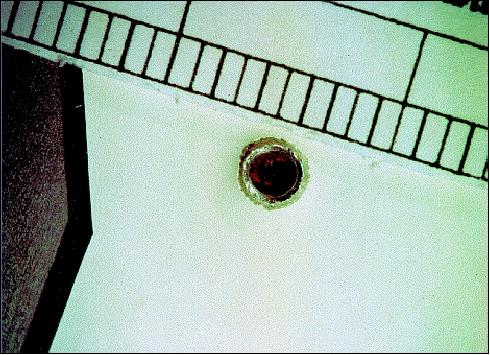
• 71 impact punctures in the outer layer of the thermal blankets were detected on the main spacecraft body (non-penetrating impacts Three impacts were found on the ESA logo plate and 11 more on the scuff plates
• The impact features identified range in size from 100 microns to several millimeters. The largest crater diameter on the solar arrays is 6.4 mm. The largest feature on the main body is a 2 mm hole in the ESA/ERNO logo plate
• A surprisingly high proportion of the impacts on the solar-cell cover glasses - about 30% - show signs of directionality by having a non-spherical crater shape.
References
1) W. Wimmer, “Eureca Re-Flights: Opportunities for Very-Low-Cost and Cost-Efficient Space Missions,” ESA Bulletin No 91, August 1997
2) W. Nellessen, “The development of the European Retrievable Carrier “EURECA”, Advances in Space Research, Vol. 16, 1995, Issue 8, pp. 5-16
3) http://imagine.gsfc.nasa.gov/docs/sats_n_data/missions/eureca.html
4) R. Mory, G. Seibert, “European Retrievable Carrier (EURECA) - an evolutionary space carrier for microgravity, Earth observation and technology demonstration,” URL: http://ia700507.us.archive.org/6/items/nasa_techdoc_19850002724/19850002724.pdf
5) K. Sommer, W. Koehler-Naumann, “Eureca: European user-friendly Retrievable Carrier,” Acta Astronautica, Volume 15, Issue 9, September 1987, pp. 621-626
6) P. Ferri, H. Hübner, S. Kellock, W. Wimmer, “The Joint ESA-NASA Operations for Eureca's Deployment and Retrieval, “ESA Bulletin, Number 76, November 1993, pp. 81-90
7) F. Dreger, J. Fertig, D. Gawthrope, S. Martin, et. al., “Eureca: The Flight Dynamics of the Retrieval,” ESA Bulletin, Number 76, November 1993, pp. 92-99
8) G. Reitz, W. Atwell, R. Beaujean, J. W. Kern, “Dosimetric results on EURECA,” Advances in Space Research, Vol. 16, 1995, pp. 131-137
9) N. Neale, P. Sever, “The inter-orbit communication (IOC) experiment EURECA Instrument 42,” Advances in Space Research (ISSN 0273-1177), Vol. 16, No. 8, 1995, pp. 47-50
10) C. Flores, R. Campesato, F. Paletta, G. L. Timò, F. Svelto, ”Post-Flight Investigation of the ASGA Solar Cell Experiment on EURECA”, Proceedings of the 1st IEEE International Conference on Photovoltaic Energy Conversion, Vol. 2, pp. 2076-2081, Dec. 05. - 09., 1994, Waikoloa, Hawaii, USA
11) “Radiofrequency Ion Thruster Heritage: EURECA,” URL: http://cs.astrium.eads.net/sp/spacecraft-propulsion/showcase/eureca.html
12) http://cs.astrium.eads.net/sp/spacecraft-propulsion/ion-propulsion/index.html
13) Helmut Bassner, Rainer Killinger, Hans Leiter, Johann Müller, “Development Steps of the RF-Ion Thrusters RIT,” IEPC-01-105 (International Electric Propulsion Conference), 2001, URL: [web source no longer available]
14) http://heasarc.gsfc.nasa.gov/docs/heasarc/missions/eureca.html
15) S. Brandt, N. Lund, A. J. Castro-Tirado, “Observations of cosmic gamma ray bursts with WATCH on EURECA,” Advances in Space Research (ISSN 0273-1177), Vol. 16, No. 8, 1995, pp. 43-46
16) E. Arijs, D. Nevejans, D. Fussen, P. Frederick, E. van Ransbeeck, F. W. Taylor, S. B. Calcutt, S. T. Werrett, C. L. Hepplewhite, T. M. Pritchard, I. Burchel, C. D. Rodgers, “The ORA occultation radiometer on EURECA; Instrument description and preliminary results,” Advances in Space Research (ISSN 0273-1177), Vol. 16, No. 8, pp. 33-36
17) D. Fussen, E. Arijs, F. Leclere, D. Nevejans, C. Bingen, “Tomography of the Earth's atmosphere by the spaceborne occultation radiometer ORA: Spatial inversion algorithm,” Journal of Geophysical Research, Vol. 102, No. D4, 1997, pp. 4357-4366
18) D Crommelynck, V Domingo, A Fichot, C Fröhlich, B Penelle, J Romero, Ch Wehrli, “Preliminary Results from the SOVA Experiment on Board the European Retrievable Carrier (EURECA),” Metrologia, Vol. 30, 1993, pp. 375-379, doi:10.1088/0026-1394/30/4/032
19) D. Crommelynck, V. Domingo, C. Froehlich, “The solar variations (SOVA) experiment in the Eureca space platform,” Proceedings of the Interdisciplinary Scientific Commission E Meeting (ME.7) of the COSPAR, 28th Plenary Meeting, The Hague, The Netherlands, June 25-July 6, 1990
20) C. Wehrli, C. Frohlich, J. Romero, “Space degradation of SOVA sunphotometers on EURECA,” Metrologia, Vol. 32, No. 6, December 1, 1995, pp. 653-656
21) J. Romero, C. Wehrli, C. Froehlich, “Solar total irradiance variability from SOVA 2 on board EURECA,” Solar Physics (ISSN 0038-0938), Vol. 152, No. 1, pp. 23-29
22) G. Thullier, M. Herse, D. Labs, T. Foujols, W. Peetermans, D. Gillotay, P. C. Simon, H. Mandel, “The Solar Spectral Irradiance from 200 to 2400 nm AS Measured by the SOLSPEC Spectrometer from the ATLAS and EURECA Missions,” Solar Physics, Vol. 214, 2003, pp. 1-22
23) .G. Drolshagen, J. A. M. McDonnell, T. J. Stevenson, S. Deshpande, L. Kay, W. G. Tanner, J. C. Mandeville, W. C. Carey, C. R. Maag, A. D. Griffiths, N. G. Shrine, R. Acetia, “Optical survey of micrometeoroid and space debris impact features on EURECA,” Planetary and Space Science, Vol. 44, Issue 4, April 1996, pp 317-340
24) R. Aceti, G. Drolshagen, J. A. M. McDonnell, T. Stevenson, “Micrometeoroids and Space Debris - The Eureca Post-Flight Analysis,” ESA Bulletin No 80, Nov. 1994, pp. 21-26, URL: http://www.esa.int/esapub/bulletin/bullet80/ace80.htm