FalconSat-5
EO
Mission complete
USAF
GPS receiver
Quick facts
Overview
| Mission type | EO |
| Agency | USAF |
| Mission status | Mission complete |
| Launch date | 20 Nov 2010 |
| Instruments | GPS receiver |
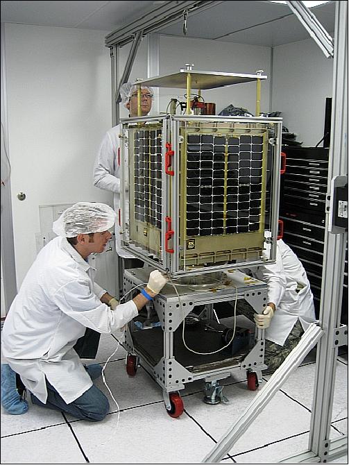
FalconSat-5 (FS-5) is the 4th student-built minisatellite demonstration mission of the USAFA (United States Air Force Academy), Colorado Springs, CO, USA. The goal of FalconSat-5 is, again, for cadets to “Learn Space by Doing Space” through real world, hands-on experience of a complete space mission design that supports DoD space science and technology objectives in the field of space situational awareness capabilities. The study of RF transmission and plasma measurement correlation in the ionosphere is the main topic of the FalconSat-5 mission to improve the ionospheric models. The spacecraft development and launch is funded by the US Air Force Space Test Program. 1) 2) 3)
• Specific project objectives are:
- Demonstrate the detection of space weather phenomena using WISPERS, iMESA, and SPCS
- Measure VHF signal distortion using RUSS
- Execute customer-funded space experiment project
- Create a reproducible system architecture
- Cadets “learn space by doing space”.
• The customers are: AFRL/RZ, AFRL/RV, AFOSR, USAFA/industry gifts
• Team partners are: UCCS (University of Colorado, Colorado Springs), and AFIT (Air Force Institute of Technology) at WPAFB (Wright Patterson Air Force Base), Ohio.
Background: The conceptual design of FalconSat-4 began in January 2005 with a symposium. The cadets completed the conceptual design in December 2006 and briefed their design to the Deputy Under Secretary of the Air Force for Space. Unfortunately, funding for FalconSat-4 was cut shortly thereafter. The Air Force Office of Scientific Research (AFOSR), however, came to the rescue with funding and a new small satellite concept, and the cadets and staff began design work on FalconSat-5.
FalconSat-5 will be an on-orbit platform for DoD space experiments with educational value that will both validate subsystems and operational procedures for future FalconSat missions and serve as an evolutionary design concept with a reproducible design architecture. In doing so, USAFA and the Astro Department forged strategic partnerships with other space organizations such as the AFRL (Air Force Research Lab), Air Force Office of Scientific Research, the USAF Space and Missile Systems Center (SMC), the French Ecole de l’Air, USAF Institute of Technology, US Naval Academy, US Naval Postgraduate School, US Military Academy, the Johns Hopkins University’s Applied Physics Lab (JHU/APL), the NRL (Naval Research Lab), University of Colorado at Colorado Springs, and many other interested organizations.
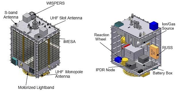
Spacecraft
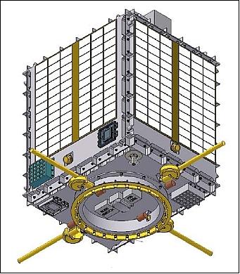
FalconSat-5 is a 3-axis stabilized minisatellite. The ADCS (Attitude Determination and Control Subsystem) uses 3 reactions wheels (MW-1000) and 3 torque rods as actuators. Attitude sensing is provided by four digital sun sensors (SpaceQuest Inc.), a 3-axis magnetometer and an onboard GPS receiver. Attitude control will be accomplished by the onboard processors using a seven-state Kalman filter based on quaternions. The nominal pointing requirements of 0.5-1º accuracy are being met using a 3-axis magnetometer and 0.1º digital sun sensors. 5) 6) 7) 8)
The EPS (Electrical Power Subsystem) consists of four surface-mounted solar panels with GaAs triple-junction cells configured in four string of 22 cells on each panel. Two battery charge regulators (BCR) are used to regulate power into a lithium-ion battery system. The nominal average power load on FalconSat-5 is between 55 and 75 W.
The design of the avionics is based on IPDR (Intelligent Power and Data Ring) nodes, an onboard computer system provided by MSI (MicroSat Systems, Incorporated) of Littleton, CO. A pair of IPDR nodes are used, designated as IPDRA and IPDRB, to control all spacecraft functions. These nodes each have a 32 bit, radiation hardened LEON-32 processor implemented in a field programmable gate array (FPGA).
One node controls all of the command and data handling (C&DH), the ADCS, the EPS, and the thruster system used for maintaining orbit position. The other node controls all of the integrated payloads, and (possibly) communication with users on the ground. Each of these processors has 128 MByte of data storage available (each is rated at 4 MFLOPs). The iMESA and WISPERS payloads are each configured with 1-2 GB of data storage and can asynchronously gather and process their own raw data. The RUSS payload has minimal data storage and streams data to the IPDR. The IPDRs have several 28 VDC switches embedded and control power to the subsystems and payloads.
The FalconSat-5 spacecraft has a launch mass of 180 kg (including margin), the design life is 3 years. The payload mass is 35.9 kg. The dimensions of the minisatellite are: 0.7 m x 0.64 m x 0.54 m.
RF communications: The S-band is used in uplink and downlink using an omnidirectional antenna. In addition, the UHF-band is used in uplink at a data rate of 9.6 kbit/s (GMSK modulation). The S-band data rates are 58 kbit/s in uplink and 115 kbit/s in downlink (GMSK modulation). The data acquisition and command functions are provided at the USAFA ground station in Colorado Springs, CO.
Launch
The FalconSat-5 spacecraft was launched on Nov. 20, 2010, (UTC) as a secondary payload aboard the STP-S26 mission of DoD. Launch vehicle: Minotaur-IV vehicle of OSC Orbital Sciences Corporation). The launch site was the Kodiak Launch Complex (KLC) on Kodiak Island, Alaska. The primary payload on this multi-payload mission is STPSat-2. 9) 10) 11)
For maximum flexibility, FalconSat-5 is also designed to meet ESPA (EELV Secondary Payload Adaptor) secondary payload constraints. The base plate of the FalconSat-5 structure was designed to use the motorized lightband (38 cm, 24 bolts) which has now become a standard requirement for STP launches. These considerations will allow alternative launch opportunities aboard DoD-sponsored Atlas V and Delta IV vehicles if a problem arises with the Minotaur IV launch.
Orbit: Near-circular orbit, altitude = 650 km, inclination = 72º, the orbital period is ~ 97.7 minutes.
Sensor Complement
(WISPERS, iMESA, SPCS, RUSS)
The objectives of the mission focus on correlated plasma and RF-RF measurements so that both the understanding of space weather and the detection of anomalous ionospheric events are the main mission goals to serve as inputs for model improvements.
Parameter | Threshold | Objective |
Attitude knowledge (all directions) | ± 1º (3σ) knowledge (WISPERS) | ±0.5º (3σ) knowledge (WISPERS) |
Attitude control (all directions) | ±2.5º (3σ) (WISPERS) | ±1.25º (3σ) (WISPERS) |
Data rate (acquisition mode) | 1.3 MB storage/orbit (iMESA) | 12.6 MB storage/orbit (iMESA) |
Slew rate | 90º in 10 minutes (RUSS) | 90º in 10 minutes (RUSS) |
WISPERS (Wafer-Integrated Spectrometers)
The objective of WISPERS is to characterize the perturbed plasma environment from thruster firings. WISPERS is an ion sensor that is capable of detecting operation of nearby ion and/or cold gas thruster and could act as a cueing sensor for defensive counterspace operations. act as a cueing sensor for defensive counterspace operations. It is a follow-on device to the FLAPS (Flat Plasma Spectrometer) payload on FalconSat-3, using improved micro-electromechanical systems (MEMS). 12) 13)
WISPERS consists of seven sensor heads covering a 15º by 15º field of view - FLAPS had five heads and a FOV of n 8º by 1º. The objective of WISPERS is to detect higher energy particles, enabling detection of nearby thruster plumes in multiple energy bands with one set of electronics and have an increased signal to noise ratio for doing so. WISPERS uses proven electrostatic energy filtering methods and its small apertures means better energy resolution to characterize energy distribution.
Instrument mass, size | 0.5 kg, 1000 cm3 |
Average power | 0.9 W |
Number of sensors | 7 |
FOV | 15º x 15º |
Energy resolution | 5-10% |
Ion energy detection | 0-2000 eV |
Plate voltage sweep | 0-50 V |
Plate factors | 2.5, 10, 30 |
iMESA (Integrated Miniaturized ElectroStatic Analyzer)
The objective of iMESA is to characterize the ambient plasma environment. The iMESA sensor package, a successor to MESA, intended for flight on FalconSat-2. The objective of iMESA is to measure plasma density, temperature, and spacecraft potential.
Background: An iMESA prototype, named SmartMESA, has already been developed and integrated onto the MISSE-6 (Materials International Space Station Experiment-6) mission in 2008 (STS-123 assembly flight 1J/A of Endeavour to ISS, March 11-26, 2008). In addition to FalconSat-5, iMESA has been selected for use on-board AFRL’s PnPSat (Plug-and-Play Satellite) and NRL's (Naval Research Laboratory) MISSE-7 mission (planned for launch on the STS-129 flight to ISS).
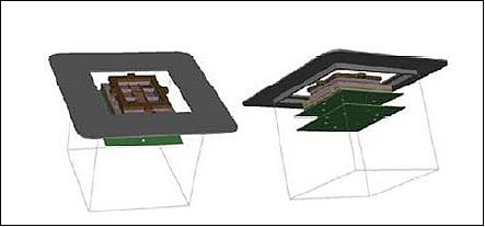
The sensor head is a series of flat metal plates, with all electronics for the package contained on a printed circuit board mounted behind the sensor head. The electronics contains an embedded microprocessor and internal flash memory. The iMESA electronics are embedded into the ceramic sensor. The iMESA sensor provides ionospheric plasma density and temperature measurements. Effectively, iMESA provides the Air Force with a simple “space weather thermometer.”
SPCS (Space Plasma Characterization Source)
SPCS is a propulsion subsystem which includes a 500 W Hall-effect thruster and an ammonia cold gas thruster. The WISPERS and iMESA payloads are plasma sensors that will investigate the ambient plasma environment and perturbations to the environment. WISPERS and iMESA will read the perturbations caused by a Hall-effect thruster and an ammonia cold gas thruster. 14)
The SPCS payload is an off-the shelf plasma source, manufactured by Busek, Inc. of Natick, MA. SPCS is propelled by 1 kg of xenon and ammonia cold gas to stimulate the space environment around the satellite and to also provide the ability for small orbital maneuvers.
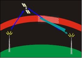
RUSS (RF Uplink Signal Strength meter)
The objective of RUSS is to characterize the VHF signal distortion to supplement in situ plasma measurements.
References
1) Martin E. B. France, William W. Saylor, “Undergraduate Small Satellite Programs at the U.S. Air Force Academy: Current Status and Future Directions,” Proceedings of the International Workshop on Small Satellites, 'New Missions, and New Technologies,' SSW2008, Istanbul, Turkey, June 5-7, 2008
2) William W. Saylor, Martin E. B. France, “Design of an Undergraduate 3-axis Space Science Satellite,” Proceedings of the IAA Symposium on Small Satellite Systems and Services (4S), Rhodes, Greece, May 26-30, 2008, ESA SP-660, August 2008
3) Douglas J. Bayley, Benjamin J. Shoptaugh, William D. Percoski, Timothy J. Lawrence, “The FalconOPS Program: Space Operations at the United States Air Force Academy,” SpaceOps 2010 Conference, Huntsville, AL, USA, April 26-30, 2010, paper: AIAA 2010-2245
4) “Air Force Academy's newest satellite nears completion,” Schriever AFB, Oct. 14, 2009, URL: http://www.schriever.af.mil/news/story.asp?id=123172709
5) William W. Saylor, Martin E. B. France, “Technology Demonstration for Autonomous Constellation and Distributed Computing,” Proceedings of the International Workshop on Small Satellites, 'New Missions, and New Technologies,' SSW2008, Istanbul, Turkey, June 5-7, 2008
6) Christin S. Hart, “Satellite Attitude Determination Using Magnetometer Data Only,” 47th AIAA Aerospace Sciences Meeting Including The New Horizons Forum and Aerospace Exposition, Jan. 5-8, 2009, Orlando, Florida
7) Cole C. Doupey, Eric D. Swenson, Lynnane E. George, Jonathan T. Black, “Finite Element Model Tuning with 3D Mode Shapes from FalconSAT-5,” 50th AIAA/ASME/ASCE/AHS/ASC Structures, Structural Dynamics, and Materials Conference, Palm Springs, CA, May 4-7, 2009, paper: AIAA 2009-2636, URL: http://www.usafa.edu/df/dfas/Papers/20082009/Finite%20Element%20Model%20Tun...
8) Shawn M. Laabs, Frank J. Panebianco, “Determining the operational limits of the FalconSat-5 satellite using thermal and orbital analyses,” URL: http://www.usafa.edu/df/dfas/Papers/20082009/Determining%20The%20Oper...
9) http://spaceflightnow.com/minotaur/stps26/101112cleanroom/
10) http://www.space.com/missionlaunches/rocket-launches-so...
11) Tom Roeder, “Cadet-built satellite hits orbit,” The Gazette, Colorado Springs, Nov. 20, 2010 [web source no longer available]
12) Aaron Q. Rogers, Larry J. Paxton, M. Ann Darrin, “Small Satellite Constellations for Measurements of the Near-Earth Space Environment,” Proceedings of the 7th IAA Symposium on Small Satellites for Earth Observation, Berlin, Germany May 4-7, 2009, IAA-B7-1104, URL: http://media.dlr.de:8080/erez4/erez?cmd=get&src=os/IAA/archiv7/Presentations/1104_2009%20IA...
13) Larry J. Paxton, “Science and Technology Challenges in Near-Earth Space Weather,” URL: http://www.ofcm.gov/swef/2009/Presentations/Session%205%20Presentations/s05-04_Paxton%20v3.pdf
14) Shawn Laabs, “Propulsion Subsystem Thermal Modeling for the FalconSat-5 Microspacecraft,” Undergraduate Research Journal at UCCS (University of Colorado at Colorado Springs), Volume 2.2, July 2009, URL: https://web.archive.org/web/20100721230450/http://ojs.uccs.edu/index.php/urj/article/viewFile/59/69
The information compiled and edited in this article was provided by Herbert J. Kramer from his documentation of: ”Observation of the Earth and Its Environment: Survey of Missions and Sensors” (Springer Verlag) as well as many other sources after the publication of the 4th edition in 2002. - Comments and corrections to this article are always welcome for further updates (eoportal@symbios.space).