FASat-Bravo
EO
Mission complete
Ozone
CCD camera
Quick facts
Overview
| Mission type | EO |
| Agency | FACh |
| Mission status | Mission complete |
| Launch date | 10 Jul 1998 |
| End of life date | 31 Dec 2001 |
| Measurement category | Ozone |
| Instruments | CCD camera, GPS receiver |
| CEOS EO Handbook | See FASat-Bravo summary |
FASat-Bravo (Fuerza Aerea Satellite - Bravo)
FASat-Bravo is the second Chilean experimental microsatellite in orbit, built under a technology transfer program between the Chilean Air Fore (FACh = Fuerza Aerea de Chile) and SSTL (Surrey Satellite Technology Ltd), Guildford, UK. The FASat program included the training of Chilenian engineers with aerospace experience (at SSTL) and to operate the Mission Control Station (ECM-Santiago) in Chile. The program's primary objective is that of acquiring the basic scientific and technological experience required to take more advanced steps.
Background: Prior to FASat-Bravo, FASat-Alfa was built at SSTL and launched on August 31, 1995 (as a secondary payload to SICH-1, a payload of Ukraine) on a Russian Cyclone-3 vehicle. Orbit of FASat-Alfa: Sun-synchronous near-circular orbit, perigee=651 km, apogee=682 km, inclination = 82.5º, period = 98.7 minutes. Unfortunately, the separation mechanism to release the microsatellite from SICH-1 failed to operate. This implied non-operation (or hibernation) for FASat-Alfa. Some time after the launch, FACh and SSTL have declared the spacecraft as lost. The SICH-1 S/C was able to perform its observation functions unharmed with the FASat S/C permanently attached to it.
The FASat program was initially proposed in 1993 by FACh to the government of Chile. In response to an invitation to tender, SSTL offered the most tempting project, including partnership construction of the probe, technological transfer and postgraduate training for FACh technicians, and was awarded the contract in 1994. 1) 2)

Spacecraft
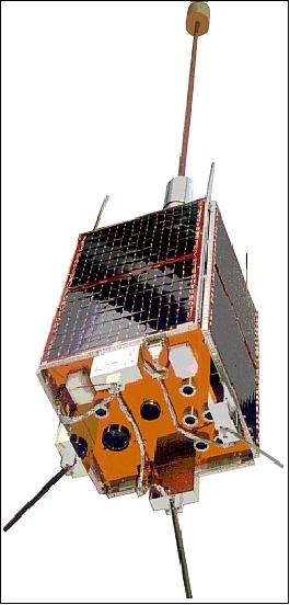
FASat uses the proven modular UoSAT bus design (MicroSat-70 platform); the spacecraft is stabilized by an Earth-pointing gravity boom and by a three-axis magneto-torquing system. First introduction of a yaw-axis reaction wheel into the micro bus to provide a nadir-pointing non-spinning platform. The FASat structure consists of 11 module trays including the battery box. Eight of the module trays are used for the platform systems, three module trays for payloads.
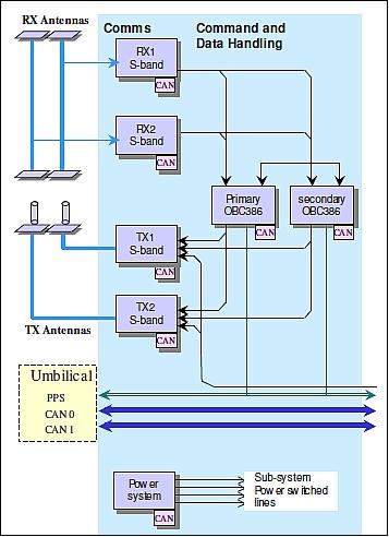
S/C mass = 55 kg, power = 35W peak (25 W orbit-average), size = 60 cm x 36 cm x 36 cm. The FASat onboard data handling design introduced a CAN (Controlled Area Network) bus, representing the first operational CAN implementation on any spacecraft. The CAN-based scalable TM/TC system removes the limitation on the number of telemetry and telecommand channels, relies on local digitization of data, and permits low speed file transfers between any two units. Most importantly, it offers a simple and standard interface for new platform equipment or payloads. The CAN system is typically implemented as a redundant bus as shown in Figure 2. 3)
Direct commanding of the spacecraft is possible over the uplink. Telemetry can be requested from any node on the CAN bus, and the CAN nodes in the power system can be commanded to switch systems on/off at the lowest level. Nodes can be bootloaded or upgraded with software (e.g. on-board computers).
Each node of the distributed system can act as a bus master when necessary, and as each computer is connected to the CAN bus, the concept of bus “master” is determined by software only.
RF communications: The RF system consists of two redundant transmitters, three receivers and the associated modulators/demodulators. Up to 600 images of 300 kByte each can be stored on the satellite's solid state data recorder. The downlink data rates are between 9.6 to 76.8 kbit/s to a single ground station in Chile. MSC-Santiago (Mission Control Station - Santiago at the Los Cerrillos Air Force Base) is in charge of controlling all aspects of satellite operations.
Launch
FASat-Bravo was launched successfully as a secondary payload [along with Thai-Paht-1 (TMSat of Thailand), TechSat/Gurwin-II (Israel), WESTPAC (Australia), and SAFIR-2 (OHB, Germany) - and RESURS-O1-4 as the primary payload of Russia/Ukraine] from the Baikonur Cosmodrome on a Zenit-2 launcher on July 10, 1998.
Orbit: Sun-synchronous near-circular orbit, mean altitude = 820 km, inclination = 98.1º, local equator crossing time at 21:37 hours, period = 101.3 minutes.
Mission Status
FASat-Bravo was operational until mid 2001 when the batteries of the spacecraft failed. The spacecraft provided an operational life of 3 years.
Sensor Complement
(OLME, EIS, DTE, GPS Receiver, EdEx)
The FASat-Bravo mission includes the same sensors/experiments as those of FASat-Alfa.
OLME (Ozone Layer Monitoring Experiment)
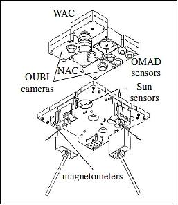
The objective of the prime instrument is to monitor the distribution of ozone. The instrument consists of two nadir-pointing UV cameras, one operating with CCD detectors, the other with UV photodiodes. The objective is ozone layer monitoring by measuring the backscattered UV solar radiation. The measurements of OLME are in particular dedicated to overflights of the antarctic and sub-antarctic regions of Chile (correlations with ground-based observations of the UV radiometric network). OLME employes the well-known SBUV (Solar Backscatter Ultraviolet) principle to determine the total column concentration of ozone. 4) 5) 6) 7)
OLME comprises two instrument packages: OUBI (Ozone Ultraviolet Backscatter Imager) - two dye-coated CCDs, capable of taking images of the backscattered UV light - and the OMAD (Ozone Mapping Detector), a four-channel UV-enhanced photodiode-based radiometer. The OUBI 380 nm camera images `albedo' UV light, while the 313 nm camera images the UV light scattered primarily from higher altitudes. The OMAD data are used in the analysis of the OUBI images, and in addition the OMAD 313 nm and 334 nm data are used to derive relative global maps of total ozone concentrations.
The OLME instrument was radiometrically and optically calibrated at SSTL and at NASA/GSFC between 1995 and 1998.
Parameter | OUBI | OMAD |
Nr of channels | 2 radiometric | 4 linear radiometric |
Spectral bands | 380 and 313 nm | 380, 334, 313 and 289 nm |
Filter bandwidth | 10 nm per channel | 10 nm per channel |
FOV (Field of View) | 27º x 37º | 11º x 11º |
Ground resolution | 4 km x 4 km | 150 km x 150 km |
Ground coverage (snapshot) | 580 km x 400 km | 150 km x 150 km |
Lens | 12.5 mm, f/1.1, AR-coated fused silica bi-convex (x 2) | 12.5 mm, f/1.1, AR-coated fused silica bi-convex (x 4) |
Detector | EEV CCD02-06-1-057, UV-enhanced dye-coated CCD | UV photodiode |
Detector size | 8.5 mm x 6.3 mm | 2.4 mm x 2.4 mm |
Output | 576 x 385 pixels (8 bit resolution) | 0-5 V (12 bit resolution) |
Quantum efficiency/ max sensitivity | 13% at 380 nm | 1.3 x 1099 V W-1 at 289 nm |
Payload size | 130 mm x 90 mm x 57.5 mm (x 2) | 130 mm x 90 mm x 57.5 mm |
EIS (Earth Imaging System)
EIS consists of two video CCD imaging cameras with two optical assemblies. The cameras are aimed in the same direction but offer a different FOV. The wide angle camera (WAC) image has a ground resolution of 2 km and a FOV of 1500 km x 1050 km (NIR 810-900 nm filter; 4.8 mm focal length). The objective is to provide snapshot imagery with good contrast between land, sea, clouds, and ice or snow. - The narrow angle camera (NAC) has a ground resolution of 200 m and a FOV of about 150 km x 100 km (red 610 - 690 nm filter, 50 mm focal length).
The cameras feature a monochromatic design with optical filters chosen to contrast ground properties, the NAC highlights variations in soil moisture content and vegetation density. An image is taken in a snapshot or staring mode (as opposed to a mechanically scanned pushbroom array) and is read from each CCD by a Transputer Data Processing Experiment (TDPE) and, after processing, provided to the On-Board Computer (OBC) and recorded. Camera sensor (both cameras): EEV CCD04-06 image sensor + chip set; 578 x 576 array (interleaved fields); anti-blooming and electronic integration control. Operational Earth imaging is performed on a scheduled snapshot basis.
WAC | NAC | ||
Nr of active pixels | 568 x 560 | Nr of active pixels | 568 x 560 |
Focal lens length | 4.8 mm | Focal lens length | 75 mm |
FOV | 102º x 73º, 1550 km x 1050 km | FOV | 6.5º x 4.8º, 93 km x 62 km |
IFOV (nadir) | 0.18º x 0.13º, 2.0 km x 2 km | IFOV (nadir) | 0.011º x 0.085º, 130 m x 100 m |
DTE (Data Transfer Experiment)
DTE employs S&F (Store & Forward) mode operation. The instrument consists of two redundant receivers and a redundant DSP (Digital Signal Processing) unit. The objective of DTE is to provide the space segment infrastructure (hardware, interfaces, firmware and software) to allow a variety of communication experiments of the following nature: a) uplink experiments, b) duplex/two-way experiments, c) data collection, d) data transfer (collection and distribution), e) downlink experiments, f) data distribution, g) technology demonstration, h) enhanced modulation/data rates/small terminals.
GPS Receiver
GPS Receiver (based on the Trimble TANS-II 6-channel receiver). GPS data provides onboard position, velocity and time reference. The data is used by OBC to generate an orbital element set and to provide scheduling and synchronization to other onboard computers, and to allow ground stations equipped with a GPS receiver to experiment with applications for real-time DGPS. FASat (like its predecessor PoSat-1) is able to autonomously determine its orbit through the processing of GPS data into orbital elements (generation of Keplerian elements using a 32-bit transputer system).
EdEx (Educational Experiment)
EdEx is intended to promote direct participation in space by Chilean schools to communicate with the FASat S/C. EdEx in turn uses DTE to generate telemetry signals that can be received by low-cost receivers and a PC. DSP chips with the DTE produce digitized voice data that may be received by simple receivers. EdEx takes place on a scheduled basis. The curricular benefit for the students arises from the following activities:
• S/C tracking (learning of some basic orbital parameters)
• Handling of satellite communications (telemetry reception)
• FASat satellite telemetry analysis (in particular those parameters related to electric and thermodynamic parameters).
References
1) M. N. Sweeting, “Nano- & Microsatellites: For Space Training,” Proceedings of the 3rd IAA Symposium on Small Satellites for Earth Observation, Berlin, Germany, April 2-6, 2001, IAA-B3-0908P, URL: http://www.dlr.de/iaa.symp/Portaldata/49/Resources/dokumente/archiv3/0908P.pdf
2) http://www.unispace3.co.cl/fach.html
3) Martin Sweeting, Alex da Silva Curiel, Wei Sun, “The “Personal Computer” Revolution in Space,” Proceedings of the 20th AIAA/USU Conference on Small Satellites, Logan, Utah, Aug. 14-17, 2006, SSC06-I-4
4) Alvaro Valenzuela, Fernando Mujica, “Design concepts for OLME experiment on board FASat-Alfa microsatellite,” Proceedings of SPIE, 'Advanced and Next-Generation Satellites,' Eds: Hiroyuki Fujisada; Martin N. Sweeting; Vol. 2583, 1995, pp. 576-584, 1995SPIE.2583..576V
5) Juan A. Fernandez-Saldivar, Craig I. Underwood, “Comparison of Results Between the Miniature FASat-Bravo Ozone Mapping Detector (OMAD) and NASA’s Total Ozone Mapping Spectrometer (TOMS),” Proceedings of the 22nd Annual AIAA/USU Conference on Small Satellites, Logan, UT, USA, Aug. 11-14, 2008, SSC08-VI-7
6) C. I. Underwood, A. Valenzuela, M. Schoenherr , M. Arancibia, M. Fouquet , “Initial in-orbit results from a low-cost atmospheric ozone monitor operating on board the FASat-Bravo microsatellite,” Philosophical Transactions: Mathematical, Physical and Engineering Sciences, Vol. 361, No 1802, Jan. 15, 2003, pp. 71-76 [web source no longer available]
7) Craig Underwood, Alvaro Valenzuela, Marcelo Schoenherr, Mario Arancibia, Marc, Fouquet, “Initial in-orbit results from a low-cost atmospheric ozone monitor operating on board the FASat-Bravo microsatellite,” Pilosophycal Transactions of the Royal Society, London, Vol. 361, 2003, pp. 71-76, URL: http://rsta.royalsocietypublishing.org/content/361/1802/71.full.pdf
The information compiled and edited in this article was provided by Herbert J. Kramer from his documentation of: ”Observation of the Earth and Its Environment: Survey of Missions and Sensors” (Springer Verlag) as well as many other sources after the publication of the 4th edition in 2002. - Comments and corrections to this article are always welcome for further updates (eoportal@symbios.space).