FormoSat-1 (Republic of China Satellite-1)
EO
OCI
Ocean colour instruments
Ocean colour/biology
Quick facts
Overview
| Mission type | EO |
| Agency | NSPO |
| Mission status | Mission complete |
| Launch date | 26 Jan 1999 |
| End of life date | 17 Jun 2004 |
| Measurement category | Ocean colour/biology |
| Instruments | OCI |
| Instrument type | Ocean colour instruments |
| CEOS EO Handbook | See FormoSat-1 (Republic of China Satellite-1) summary |
FormoSat-1 / ROCSat-1 (Republic of China Satellite-1)
ROCSat is a satellite program of NSPO (National Space Program Office) of Taiwan. A major program objective was to provide a national (NSPO, industry, university, etc.) capability and to create an infrastructure and environment for state-of-the-art space age technology and research. 1) 2)
Note: A public naming competition took place in Taiwan in 2004 with regard to the ROCSat satellite program. At the end of this contest, the ROCSat program was given the new name of FormoSat in December 2004. Hence, ROCSat-1 became FormoSat-1.
Spacecraft
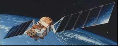
The ROCSat-1 spacecraft was developed/built by TRW (Space & Electronics Group) of Redondo Beach, CA, as a cooperative development project between TRW and NSPO, offering training capabilities and participation for NSPO engineers in S/C design, testing, and operation/control. The joint development effort started in June 1994. In May 1997, the S/C was returned to NSPO for integration and testing. Some satellite components (OBC, remote interface unit, filter/diplexer and S-band antenna, and solar panels) and instruments/experiments were developed at industry and institutes/facilities in the Republic of China (ROC). 3) 4) 5) 6) 7)
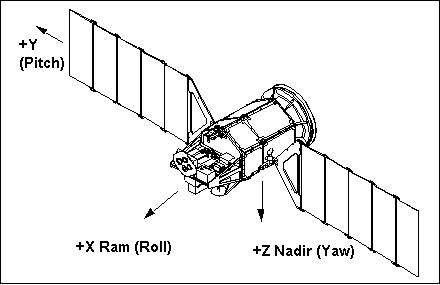
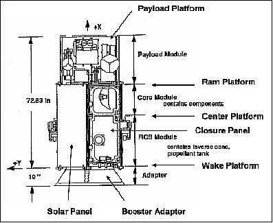
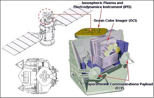
The ROCSat-1 S/C structure (bus) is a hexahedron in shape and of modular design, accommodating payload growth. The hexahedron has a size of 2.1 m (height) x 1.1 m, the deployed vehicle has an overall length of 7.2 m. The S/C is three-axis stabilized with a reaction control subsystem module, providing pointing control of 0.5º, pointing knowledge of 0.1º and a stability of 0.01º/s. The major components of the ADCS (Attitude Determination and Control Subsystem) consist of two scan wheel assemblies, two reaction wheel assemblies, three gyro reference assemblies, three magnetic torque rods, four fine sun sensors, and all the associated electronics.
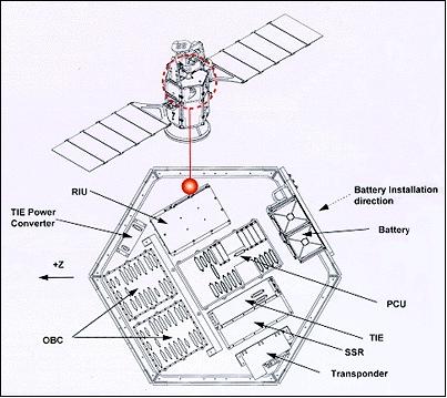
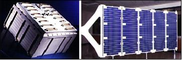
Spacecraft dimensions: 1.10 m diameter and 2.1 m in height (hexahedron shape). Solar arrays of size 1.16 m x 2.46 m provide 450 W of power (645 W max). A 21 Ah NiCd battery cell is used to provide power during the eclipse period. A reaction control module provides orbit trim capability. Total S/C mass at launch was 401 kg (including propellant), the S/C design life is two years with a goal of 4 years. The C&DH (Command & Data Handling) equipment consists of onboard computers, remote interface units, GPS equipment, transponder interface electronics, and solid state recorder.
Taiwanese manufactures provided the following spacecraft components:
• OBC (Onboard Computer) of Acer Sertek Inc.
• Remote interface unit (Trans System Inc.)
• Filter/diplexer (Victory Industries)
• S-band antenna (Victory Industries)
• Solar panel (Shih-Lin Electric Corp.)
Launch
ROCSat-1 was launched Jan. 26. 1999 (UTC) from Cape Canaveral, FLA, on an Athena-1 vehicle (Lockheed Martin). Spacecraft operations and data processing are performed from NSPO facilities at Hsin-Chu City (Satellite Mission Operations Control Center), there are two tracking stations at Chung-Li and Tainan, Taiwan.
RF communications are provided in S-band (uplink frequency = 2.039 GHz, downlink frequency = 2.215 GHz, bandwidth = ±15 MHz, RHCP polarization, power = 6 W). The uplink data rate is 2 kbit/s, the downlink data rate is 1.4 Mbit/s. Onboard storage is provided for 2 Gbit of data. The CCSDS communication protocols are being used for TT&C support. In addition, ROCSat-1 carries an experimental Ka-band (20-30 GHz) communication system, ECP (Experimental Communication Payload).
Orbit: Circular orbit, altitude = 600 km, inclination = 35º, period = 96.7 min. The low inclination orbit implies very good spatial coverage in local time and longitude (the nodal precession makes the spacecraft drift around the Earth every 52 days). In addition, the FormoSat-1 mission takes place during the active phase of solar cycle 23, when space weather phenomena are rather intense.
Mission Status
FormoSat-1/ROCSat-1 provided 5 1/2 years of operational service (design life of 2 years). The spacecraft ended its mission on June 17, 2004 and was decommissioned on July 16, 2004. 8)
• On July 14, 2000, the IPEI device detected an 'ionospheric density hole' above Brazil, the biggest magnetic storm for nearly 20 years occurred on that day. During the event, an extensive two-dimensional profile of the ionospheric density hole was measured by a satellite for the first time.
Sensor Complement
OCI (Ocean Color Imager)
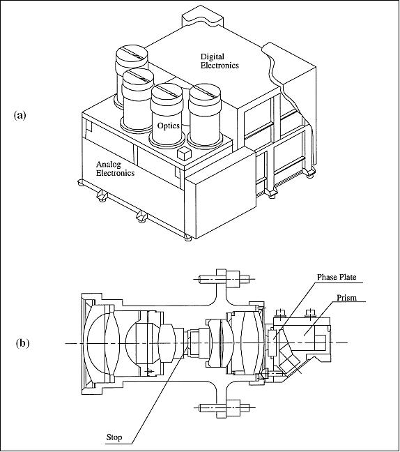
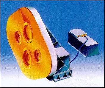
OCI was built by NEC Corp. of Japan. Objective: Collection of visible and near-infrared radiances over low latitude oceans. The science goals are: mapping of pigment distribution, study of marine productivity and the dynamics of meso-scale eddies, and estimation of influence of the atmospheric aerosols in remote sensing. The instrument is an all-refractive spectral radiometer designed to sense in six spectral bands (443 - 865 nm) with 800 m spatial resolution. Swath width = 700 km (FOV=60.4º). 9) 10) 11)
Besides a redundant 555 nm band (band 4 is also band 7), the OCI has six different visible and near IR spectral bands that are similar to, but fewer than those of the SeaWiFS instrument on OrbView-2 (Note: The SeaStar mission was renamed in 1997 to OrbView-2).
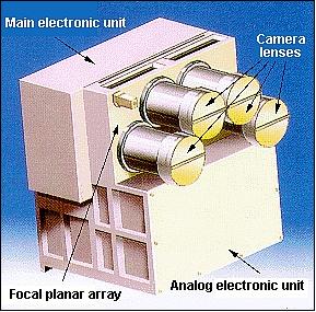
The OCI instrument consists of three modules: OU (Optical Unit), AEU (Analog Electronic Unit) and MEU (Main Electronic Unit). The OU consists of four camera heads with seven focal planes each with a Thomson TH7811 linear array CCD device for detecting the input radiance. Two focal planes (B1/B3, B2/B4, or B5/B6) share a camera head that has an eight-lens telecentric telescope subsystem with 19.5 mm focal length and 60.7º FOV to give 702 km swath width at 600 km altitude. B7 uses a standalone camera head with a lens subsystem similar to that of the others.
Spectral bands | B1 | B2 | B3 | B4 | B5 | B6 | B7 |
Center wave length (nm) | 444 | 490 | 512 | 555 | 670 | 869 | 555 |
Tolerance (nm) | ±3 | ±4 | ±4 | ±4 | ±4 | ±5 | ±4 |
FWHM in nm, bandwidth | 20 | 20 | 20 | 20 | 20 | 40 | 20 |
Minimum SNR at EOL | 450 | 450 | 450 | 450 | 350 | 350 | 350 |
MTF @ Nyquist Frequency | 0.53 | 0.55 | 0.52 | 0.52 | 0.53 | 0.47 | 0.51 |
Instrument operating modes | FB, NI-A, NI-B, RGB, CA, SBY, OFF, SUV | ||||||
Instrument mass, power | 15.2 kg, 33 W (peak), 18 W (standby) | ||||||
Date rate | 655.5 kbit/s in mode FB via RS-422 (inclusive CCSDS overhead) | ||||||
Data quantization | 12 bit | ||||||
Imaging method, detectors | Pushbroom scanning, linear CCD arrays with 1728 cells per line | ||||||
Pixels per band | 896 pixels (832 double+64 single cells) | ||||||
Absolute radiance accuracy | 5% or better at BOL | ||||||
Integration time | 115.8 ms | ||||||
Co-registration error (band 4) | Along-track: ≤ 0.65 IFOV; cross-track: ≤ 0.97 IFOV | ||||||
Instrument optics | Four telecentric dioptric systems (lens system) | ||||||
Polarization sensitivity | ≤ 2% | ||||||
OCI calibration: The pre-flight calibration and validation activities for the OCI were executed at the NEC Corporation in Yokohama, Japan for sensor levels, and at the NSPO in Taiwan prior to integration into the ROCSat-1 spacecraft. 12) 13)
Although OCI has been designed without any moving component to achieve reliability as high as 0.991 at the end of two years in orbit, one major cause of change in the radiometric response is the degradation of optical transmittance due to exposure to environmental radiation and contamination of the optics by outgassing.
The following in-flight calibrations were conducted:
• Repetitive reflectance measurements were conducted on reference target sites.
• Cross-platform in-flight calibrations were conducted with SeaWiFS on the SeaStar spacecraft of OrbImage, Dulles, VA (SeaStar was renamed to OrbView-2 in 1997).
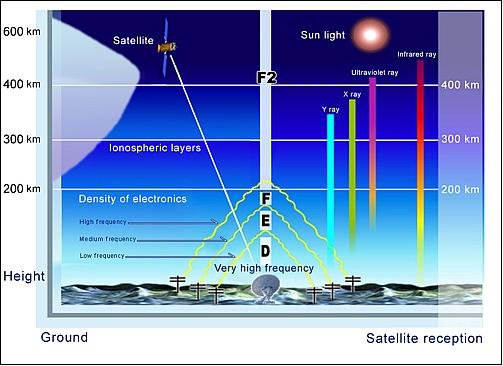
IPEI (Ionospheric Plasma and Electrodynamics Instrument)
Objective: Measurement of the Earth's upper atmosphere, in particular the ionospheric plasma and electrodynamic effects at 600 km altitudes to gain a better understanding of the ionospheric structure and effects on radio communications in the low and middle latitudes (up to 35º). IPEI is a cooperative project between the National Central University of ROC and the University of Texas at Dallas (UTD). 14) 15) 16)
Instrument/Subsystem | RPA | IDM | IT |
Measurement | Ion temperature and RAM velocity | Ion transverse velocity component | Total ion concentration |
Sampling rate | Normal mode: 332/s | Normal mode: 32/s | Normal mode: 32/s Fast mode: 1024/s |
Envelope dimension | SEP: 19 cm x 47 cm x 41.9 cm; MEP: 12.8 cm x 27.9 cm x 13.9 cm | ||
Instrument mass, power | 9.4 kg, 10 W | ||
FOV | 45º x 45º | ||
Operating temperature | -10ºC to about 40ºC | ||
Date rate | Normal mode: 2.2 kbit/s; Fast mode: 53.38 kbit/s | ||
Duty cycle | Normal mode: 85%, Fast mode: 15% | ||
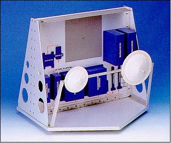
ECP (Experimental Communication Payload)
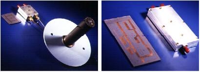
ECP was built by MTI (Microelectronic Technology Inc.) of ROC and NEC Corp. of Japan. ECP is a microwave instrument with the objective to conduct various low-altitude satellite communication experiments, in particular the collection of system characteristics and their relationship to different communication technologies (20-30 GHz Ka-band telecommunications). 17) 18) 19)
Antenna coverage | ±65º conic |
Duty cycle (averaged) | 8% of an orbital period |
Bandwidth | 27 MHz |
Power consumption | Operating: 85 W peak, on-orbit power: 25 W |
Frequencies | Uplink: 28.25 GHz, downlink: 18.45 GHz, beacon: 19.5 GHz |
Instrument mass | 18.43 kg |
Volume | Transponder: 20 microwave boxes distributed in two sides of the payload adapter. Antennas: 25.4 cm diameter (transmit), 20.3 cm (receive) |
Transmitter power | 10 W (communication channel), 1.77 W (beacon signal) |
Polarization | Transmit: LHCP; receive: RHCP |
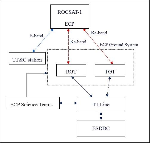
The ECP consists of ground, space, and science segments. The ground segments consists of a fixed ground terminal and a transportable terminal. The space segment provides a bent-pipe transponder and a downlink beacon transmitter. The uplink and downlink frequencies are 28.25 GHz and 18.45 GHz, respectively, while the downlink beacon operates at 19.5 GHz.
Ground Segment
The ROCSat-1 ground segment consists of six elements:
• MOC (Mission Operations Center) with control over the spacecraft
• TT&C (Telemetry, Tracking and Command) provides direct station access to the S/C for tracking, telemetry collection, and satellite commanding
• FDF (Flight Dynamics Facility) performs orbit and attitude determination and control computations, ephemeris data management, and mission planning support
• MCC (Mission Control Center) provides the capability to support ROCSat-1 policy decisions and mission planning.
• SCC (Science Control Center) is responsible for science instrument planning and scheduling, data processing, archive, and distribution
• GCN (Ground Communication Network) provides the communications among all ROCSat-1 elements and to external elements.
References
1) David F. Chu, “Development of ROCSat-1 Program,” TAO (Terrestrial, Atmospheric and Oceanic Sciences), Supplementary Issue, 1-6, March 1999, URL: http://tao.cgu.org.tw/index.php/articles/archive/space-science/item/337-199910s1rocsat
2) Paul Cheng. I Chen, “ROCSat-1 Satellite Program and OCI Sensor Update,” July 24, 1998, URL: http://140.112.68.31/omisar/wksp.mtg/ocare98/rocsat1.ppt
3) P. Chen, L .S. Lee, Shin-Fa Lin, “OCI and ROCSat-1 Development, Operations, and Applications,” Journal of the Korean Society of Remote Sensing, Vol.15, No.4, 1999, pp.367-375
4) http://www.nspo.org.tw/2005e/projects/project1/intro.htm
5) W. Ferster, “ROCSat Set to Launch Taiwan's Space Program,” Space News, Feb. 1, 1999, p. 7
6) C. F. Lillie, R. E. Sharples, Ho Pen Chang, “The ROCSat-1 Spacecraft,” AIAA Space Programs and Technologies Conference, Huntsville, AL, Sept 26-28, 1995, AIAA-95-4078
7) http://www.globalsecurity.org/space/world/taiwan/comm.htm
8) L. Wu, S.-S. Chen, J. Ju-Chen Yaung,, “Space Program in Taiwan,” Proceedings of ASC (Asian Space Conference), Chiang Mai, Thailand, Nov. 22-26, 2004
9) http://www.nspo.org.tw/2005e/projects/project1/instrument.htm
10) Wei-Song Lin, Wen-Hao Sung, “Tracking the radiometric performance of the ROCSat-1 Ocean Color Imager,” Journal of the Chinese Institute of Engineers, Vol. 26, No. 4, pp. 481-491, 2003, URL: http://www.crt.ntust.edu.tw/jcie/pdf/26-4-PDF/481-491.PDF
11) Hsien-Wen Li, Chung-Ru Ho, Nan-Jung Kuo, Wei-Peng Tsai, Shih-Jen Huang, “Ocean Color Imager - Taiwan's First Spaceborne Ocean Color Sensor,” Proceedings of the 8th International Offshore and Polar Engineering Conference, Montreal, Canada, May 24-29, 1998
12) Wei-Song Lin, Jenn-Yii Wu, Heng-Je Chiu, Chun-Sheng Chen, Yu-Jen Chang, “Sensor Calibration of the Ocean Color Imager,” TAO, Supplementary Issue, pp. 63-84, March 1999, URL: http://tao.cgu.org.tw/index.php/articles/archive/space-science/item/341-199910s63rocsat
13) Hsien-Wen Li, Chung-Ru Ho, Nan-Jung Kuo, Chun-Te Chen, Wei Peng-Tsai, “A Comparison of OCI and SeaWiFS Satellite Imagery in the Waters Adjacent to Taiwan,” TAO, Vol. 10, No 4, pp. 873-883, December 1999, URL: http://tao.cgu.org.tw/index.php/articles/archive/space-science/item/335-1999104873rocsat
14) Shin-Yi Su, Huey Ching Yeh, Roderick A. Heelis, Jing-Mei Wu, Shu Chih Yang, Li-Fan Lee, Hsin Liang Chen, “The ROCSat-1 IPEI Preliminary Results: Low-Latitude Ionospheric Plasma and Flow Variations,” TAO, Vol. 10, No 4, pp. 787-804, Dec. 1999, URL: http://tao.cgu.org.tw/index.php/articles/archive/space-science/item/329
15) Shin-Yi Su, “Using ROCSat-1 (FormoSat-1) Data to Study the Topside Ionosphere at 600 km Altitude (1),” Nov. 11, 2005, URL: http://140.115.111.70/CAWSES-AOPR/SySu_1.pdf
16) S.-Y. Su, M. Q. Chen, C. K. Chao, C. H. Liu, “Global/Seasonal/Local-Time Variations of Ion Density Structure at Low-Latitude Ionosphere and Their Relationship to the Post-Sunset Irregularity Occurrences,” 4th Asian Space Conference, Oct 1-3, 2008, Taipei, Taiwan, URL: http://www2.nspo.org.tw/ASC2008/4th%20Asian%20Space%20Conference%...
17) C. K. Chen, K. Tseng, “ROCSat-1 Ka-Band Experimental Communication Payload Operations,” AIAA SpaceOps 2002, Oct. 9-12, 2002, Houston, TX, USA, URL: http://www.aiaa.org/Spaceops2002Archive/papers/SpaceOps02-P-T4-30.pdf
18) Tah-Hsiung Chu, Chao-Hsiung Tseng, Shin-Der Yang, Chung-I Chi, “A Ka-band receiving terminal for measuring ROCSat-1 ECP beacon signals,” Journal of the Chinese Institute of Engineers, Vol. 24, No. 1, pp. 29-36, 2001, URL: http://www.crt.ntust.edu.tw/jcie/pdf/24-1-PDF/29-36.PDF
19) Shun-Peng Shih, Yen-Hsyang Chu, “Ka Band Propagation Experiments of Experimental Communication Payload (ECP) on ROCSat-1 – Preliminary Results,” TAO, Supplementary Issue, 145-164, March 1999, URL: http://tao.cgu.org.tw/index.php/articles/archive/space-science/item/346-199910s145rocsat
The information compiled and edited in this article was provided by Herbert J. Kramer from his documentation of: "Observation of the Earth and Its Environment: Survey of Missions and Sensors" (Springer Verlag) as well as many other sources after the publication of the 4th edition in 2002. - Comments and corrections to this article are always welcome for further updates (eoportal@symbios.space).