GOES-N, O, P
EO
Atmosphere
Ocean
Cloud type, amount and cloud top temperature
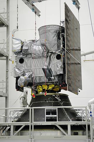
Geostationary Operational Environmental Satellite-N, -O and -P (GOES-N, -O, -P, designated GOES-13, -14, -15 after launch, respectively) refer to the three satellites that follow the GOES I-M series, known as the extended second-generation GOES series. The mission aims to monitor surface and environmental conditions on Earth, and produce observational data to provide reliable and continuous storm warning systems for protection of life and property. The missions launched in May 2006, June 2009 and March 2010 respectively, with GOES-N operations managed by the United States Space Force (USSF), with GOES-O and -P operations managed by the National Oceanic and Atmospheric Administration (NOAA).
Quick facts
Overview
| Mission type | EO |
| Agency | NOAA, USSF |
| Mission status | Operational (extended) |
| Launch date | 24 May 2006 |
| Measurement domain | Atmosphere, Ocean, Land |
| Measurement category | Cloud type, amount and cloud top temperature, Liquid water and precipitation rate, Atmospheric Temperature Fields, Aerosols, Multi-purpose imagery (ocean), Radiation budget, Multi-purpose imagery (land), Surface temperature (land), Surface temperature (ocean), Atmospheric Humidity Fields, Ozone, Atmospheric Winds |
| Measurement detailed | Cloud top height, Ocean imagery and water leaving spectral radiance, Aerosol absorption optical depth (column/profile), Cloud cover, Precipitation intensity at the surface (liquid or solid), Cloud imagery, Aerosol Extinction / Backscatter (column/profile), Upward long-wave irradiance at TOA, Aerosol effective radius (column/profile), Fire temperature, Fire fractional cover, Atmospheric specific humidity (column/profile), O3 Mole Fraction, Atmospheric temperature (column/profile), Land surface temperature, Sea surface temperature, Cloud top temperature, Wind profile (horizontal), Atmospheric stability index |
| Instruments | LRIT, SEM (GOES), S&R (GOES), SXI, DCS (GOES-R Series), Imager, A-DCS4, GOES Comms, Sounder |
| Instrument type | Imaging multi-spectral radiometers (vis/IR), Space environment, Other, Communications, Data collection, Atmospheric temperature and humidity sounders |
| CEOS EO Handbook | See GOES-N, O, P summary |
Summary
Mission Capabilities
Instruments found on GOES-N, -O and -P are the same as the preceding satellites (GOES-I-M), however there is an improvement in horizontal resolution on GOES-O and -P for the thermal infrared imager, from 8 km to 4 km. The instruments include the GOES Imager, GOES Sounder, Space Environment Monitor (SEM), Solar X-ray Imager (SXI) and Data Collection System (DCS).
The GOES Imager is a multispectral five-channel instrument that images the Earth’s surface to analyse cloud cover, water vapour and oceans to identify storm development. The GOES Sounder is a 19-channel radiometer used to sense emitted thermal energy and reflected solar energy to calculate vertical profiles of temperature and moisture. SEM is a package that measures solar radiation in the X-ray and Extreme Ultraviolet (EUV) regions, as well as the magnetic field and energetic particle environment during orbit. SXI monitors the sun’s X-rays to detect solar flares at an early stage to ensure human and space mission safety. DCS relays data from the satellite to the receiving stations on Earth.
Performance Specifications
The GOES Imager utilises a Cassegrain telescope to image in one visible spectrum (VIS) band, two midwave infrared (MWIR) bands and two thermal infrared (TIR) bands, with a pixel size of 4 km x 4 km on MWIR and TIR bands (except for the TIR band that images cloud cover and height, where an 8 km x 8 km pixel size is found on GOES-N only). The pixel size in the VIS band is 1 km x 1 km. The GOES Sounder also utilises a Cassegrain telescope, imaging in nine TIR, six MWIR, three shortwave infrared (SWIR) and one VIS band. SEM measures two solar X-ray flux (XRS) bands and five EUV bands, as well as detecting protons in seven bands, alpha particles in six bands and electrons in three bands.
The orbits of GOES satellites are geostationary, with an altitude of 35,786 km above the equator. The satellites are stationed at different locations, with GOES-East and GOES-West being the primary locations of orbit, located at 75° W and 135° W respectively. Another location in orbit is utilised for on-orbit storage, which means that the satellite is in orbit as a backup should one of the existing satellites fail.
Space and Hardware Components
GOES N-P series spacecraft are based on the BSS (Boeing Satellite Systems) 601 satellite platform that allows for the provision of continuous real-time observations of dynamic events and better pointing capabilities to locate severe weather events. Furthermore, there are onboard propulsion systems to allow for the adjustments in orbit between GOES-East and GOES-West locations, as well as the need to manoeuvre the on-orbit spare satellite into operation should one of the satellites become faulty. GOES-13 was transferred to the United States Air Force, whilst GOES-14 and -15 are operational as on-orbit storage satellites.
GOES-N, O, P Satellites (Extended 2nd Generation Series)
Spacecraft Launch Operational Status Sensor Complement References
Overview
For a number of years the designation GOES-Next (N) was used to identify the first of the satellites that would follow the GOES I-M series. It was also thought this GOES-N would be the start of a totally new generation satellite series. However, during the time frame of about 1992-95, NOAA and NASA have come to realize that a new generation satellite series would take at least a decade to define, develop, manufacture, and to launch. This new situation made both parties (NOAA, NASA) realize it would need a few more clones of the current GOES I-M series to maintain continuity of GOES service prior to the GOES Next being available.
What has evolved is a program that is buying 3-4 additional GOES I-M satellites beyond the GOES I-M series. These will then be labeled GOES N through Q. GOES-R is considered to be the first of a new 3rd generation of three-axis stabilized satellites with an entirely new sensor complement - comprised of improved spacecraft and instrument technologies. The definition phase of this 3rd generation program started in 2000 (information provided by Roger Heymann of NOAA).
In January 1998, BSS (Boeing Satellite Systems Inc. of El Segundo, CA (formerly Hughes Space and Communications Company), was awarded a contract from NASA/GSFC to design, manufacture, and launch two GOES satellites, namely GOES-N and -O (with two options for -P and -Q). However, the GOES-Q option spacecraft was cancelled in 2004. The GOES-N,O,P contract is fixed price with delivery on-orbit. Note: the former BSS was in turn renamed to BSIS (Boeing Space and Intelligence Systems). 1) 2)
The major goals of the extended 2nd generation GOES program are:
• To maintain continuous, reliable operational, environmental, and storm warning systems to protect life and property
• To monitor the Earth's surface and space environmental conditions
• To introduce improved atmospheric and oceanic observations and data dissemination capabilities
• To develop and provide new and improved applications and products for a wide range of US agencies, state and local governments, and private users.
GOES-8 | Apr. 13, 1994 | First second generation S/C (3-axis stabilized); S&RSAT became operational on GOES-8; GOES-8 operated for over 6.5 years (design life of 3 years). GOES-8 was functioning at 75º W. The S/C was deactivated on May 5, 2004 and boosted into a higher orbit (350 km above GEO) | 2 nd Generation S/C |
GOES-9 | May 23, 1995 | GOES-I to -M S/C were built by SS/L; In July 2002, GOES-9 was removed from operational service in 1998 - to act as backup for GMS-5 of Japan, starting in 2003 | |
GOES-10 | April 25, 1997 | In the initial mission, the S/C suffered a solar array malfunction. A recovery procedure was performed to invert the S/C and operate the solar array in the reverse direction. The S/C became operational in July 1998. It replaces GOES-9 which had problems with its attitude control system. GOES-10 is positioned at 135º W. The design life of KLM S/C is 5 years. | |
GOES-11 | May 3, 2000 | GOES-11 was launched into a storage orbit at 105º W (backup) | |
GOES-12 | July 23, 2001 | GOES-M is the last of the 2nd generation S/C built by SS/L | |
GOES-13 | May 24, 2006 | GOES-N, and -O (options for -P and -Q) S/C are being built by BSS (Boeing Satellite Systems) on a Boeing 601 S/C platform, the S/C feature a star tracker for pointing | 2nd Generation S/C extended, built by BSIS (Boeing Space and Intelligence Systems) |
GOES-14 | June 27, 2009 | NASA contracted with BSIS (Boeing Space and Intelligence Systems) to build and launch the GOES-O spacecraft. About 3 weeks after launch, control is turned over to NASA. About 5 months later, NASA will transfer operational control of GOES-14 to NOAA. The S/C will be stored on orbit and available for activation should one of the operational GOES satellites degrade or exhaust its fuel.. | |
GOES-15 | March 4, 2010 | GOES-P was built for NASA and NOAA by BSIS. GOES-15 was placed in on-orbit storage as a replacement for an older GOES satellite | |
GOES-Q |
| NOAA may not exercise the option for GOES-Q; - In fact, GOES-Q was cancelled in 2004 | |
GOES-R | Nov. 19, 2016 | Start of 3rd generation satellites and instruments (ABI, SUVI, EXIS, GLM, SEISS, MAG) | 3 rd Generation S/C |
GOES-S | 2018 planned |
|
Spacecraft
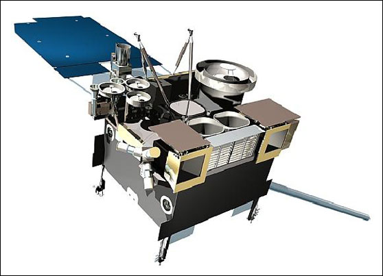
The space segment of GOES is comprised of two spacecraft in orbit, one located nominally at 75º W and one at 135º W. The GOES-N-P series spacecraft are based on the BSS 601 platform (El Segundo, CA), a three-axis body stabilized bus design providing continuous observations of dynamic events in real-time and enhanced pointing capabilities for more accurate localization of severe storms and other weather phenomena, resulting in more precise warnings to the public. 4) 5) 6) 7) 8)
Spacecraft bus size | Length = 4.2 m, width = 1.88 m |
Spacecraft on-orbit configuration | Length = 8.4 m, (solar array to spacecraft body) |
Solar array panel | 8.2 m, yoke panel = 2.3 m x 1.8 m |
Spacecraft launch mass | 3,209.5 kg, dry mass = 1,543 kg |
Spacecraft power | 2.3 kW at BOL, 2 kW at EOL (End of Life) |
Propulsion (liquid apogee motor) | Fuel: Monomethylhydrazine, 490 N |
Stationkeeping thrusters (12) | 9 N, each, bipropellant |
Spacecraft design life | - Five years of operations plus two years of on-orbit storage |
RF communications | S-band: 9 downlinks, 5 uplinks (include telemetry and command data) |
Antennas | 3 S/L Band, cup-shaped with dipole |
The power subsystem has been improved with the use of a single panel solar array that contains high-efficiency dual-junction gallium-arsenide (GaAs) solar cells.
BSIS provides the communication subsystem along with a search and rescue capability (GEOS&R) to detect distress signals from the ground segment. BSS also integrates three government-provided primary observation instruments.
The GOES N-P series delivers considerably improved INR (Image Navigation and Registration) performance compared to that of the previous generation. The GOES-N spacecraft is entirely new and includes advanced GN&C (Guidance, Navigation, and Control) features and improved instrument accommodations that enable dramatically improved INR performance within an evolved version of the GOES I-M INR architecture.
The new INR features include: 9) 10)
• SIAD (Stellar Inertial Attitude Determination) for fine attitude determination determination, consisting of three star trackers and a hemispherical resonating gyroscope package
• Optical bench accommodations for the Imager and Sounder instruments
• IMC (Image Motion Compensation) implementation improvements
• Closed-loop DMC (Dynamic Motion Compensation) that is added to the IMC to compensate for residual attitude control error - replacing the open-loop MMC (Mirror Motion Compensation) and SMC (Spacecraft Motion Compensation) of the GOES I-M series
• ISEC (Instrument Systematic Error Compensation) to compensate for systematic scan errors that are functions of scan coordinates
• INR operations to accommodate thruster maneuvers for momentum
• INR operations for continuous operation across eclipses
• INR operations following yaw flips.
SIAD (Stellar Inertial Attitude Determination) is an advanced attitude sensor of the GOES-N to P series spacecraft AOCS, developed at BSIS. The requirements call for a pointing accuracy of < 0.01º and to use SIAD as a mirror controller for the GOES Imager and GOES Sounder instruments in real-time (dynamic compensation of S/C jitters to an accuracy of 10 µrad, 3σ). This technology is referred to as DMC (Dynamic Motion Compensation), permitting a high precision "virtual platform" to be used for imaging and sounding. The primary design driver of SIAD is the 10 µrad accuracy performance requirement. 11)
The GOES Imager and GOES Sounder are collocated with SIAD on a common baseplate attached to the nadir panel. The SIAD instrument package consists of three star trackers (CT 602 by BATC) and a dual string HIRU (Hemispheric Inertial Reference Unit) package of Northrop Grumman. Attitude rates are being measured by HIRU, a 6-state Kalman filter, implemented in the spacecraft control processor, determines the spacecraft 3-axis attitude. The SIAD system is connected by the dual MIL-STD-1553 data bus. The star trackers feature a FOV of 8º x 8º, five stars may be tracked simultaneously. A simulation test analysis validated the functionality and performance of SIAD in 2001.
The ACS (Attitude Control Subsystem) of the GOES N-P series spacecraft consists of redundant microprocessor-based control electronics, sun sensors, Earth sensors, star trackers, gyros, reaction wheel assemblies (RWAs), a solar array drive (SAD), and an X-ray positioner (XRP) mechanism.
The nominal on-orbit attitude control operations are based on a zero momentum concept that provides precise pointing for the Imager and Sounder, communications service equipment, and scientific instruments. Bus control is accomplished by applying torque to internal RWAs (each wheel is capable of storing 75 Nms of momentum and of providing 0.2 Nm of reactive control torque). The SAD and XRP articulate the suite of scientific instruments mounted on the instrument mounting platform (IMP). Twelve 9.25 N bipropellant thrusters provide attitude control during orbit maneuvers. The ACS during transfer orbit is mostly passive with control applied only during re-orientations, spin speed changes, or liquid apogee motor (LAM) burns.
Parameter | GOES-I-M | GOES-N-P | GOES-R |
Era | 1994+ | 2006+ | 2015+ |
Navigation | 112 µrad (day) | 65 µrad | 28 µrad (1 km) |
Frame-to-Frame | 50 µrad (day) | 36 µrad | 21 µrad |
Frame-to-Frame | 84 µrad (day) | 49 µrad | 21 µrad |
Legend to Table 3: All requirements are 3σ (99.7%) and apply to both East-West (EW) and North-South (NS) directions with relaxations under special circumstances. Distance equivalent at subsatellite point is 1 km = 28 µrad.
The INR system closes its control loop on the ground, as shown in Figure 3, with elements originally developed or evolved for GOES-N by Carr Astronautics and Integral Systems; comprising a:
• SPS (Sensor Processing System) that radiometrically calibrates image pixels, formats the GVAR (GOES Variable transmission format) product that is broadcast to the user community through the GOES spacecraft, conducts ranging through the GVAR link, and detects and measures stars when the instruments are in star-sense mode.
• RPM (Replacement Product Monitor) or simply PM that measures the locations of VIS and IR landmarks for orbit determination and INR quality control.
• OATS (Orbit and Attitude Tracking System) that estimates the orbit and attitude parameters for each instrument and creates IMC coefficient sets that are uploaded to the spacecraft.
• GOES NOP Telemetry and Command System (GTACS) that commands the spacecraft and identifies stars detected by the SPS according to the operational schedule.
• PES (Performance Evaluation System) that models the entire INR system and serves as a high fidelity design validation and implementation test tool.
The INR system closes one per day through the ground with the production of new sets of IMC coefficients that are then uploaded, enabled, and used for a period of 24 hours. There will nominally be one HK maneuver during any given 24-hour period and an eclipse period during eclipse season. IMC coefficient sets are produced for pre-maneuver and post-maneuver cases and special IMC sets are produced for eclipse periods. The DMC is generated in real-time onboard the spacecraft from the SIAD error signal. ISEC calibrations are infrequent and have not yet been applied.
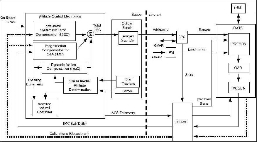
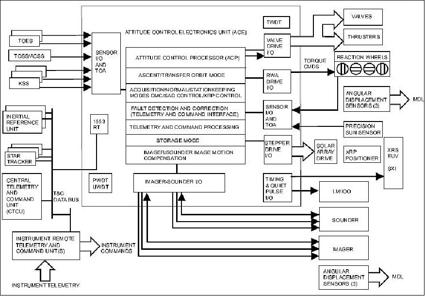
The ACS (Attitude Control Subsystem) consists of redundant microprocessor-based control electronics, sun sensors, earth sensors, star trackers, gyros, RWAs (Reaction Wheel Assemblies), a SAD (Solar Array Drive), and an XRP (X-ray Positioner) mechanism. A block diagram of the ACS is shown in Figure 4.
Normal on-orbit attitude control operations are based on a zero momentum concept that provides precise pointing for the Imager and Sounder, communications service equipment, and scientific instruments. Bus control is accomplished by applying torque to internal RWAs. The SAD and XRP articulate the suite of scientific instruments mounted on the IMP (Instrument Mounting Platform). Twelve 9.25 N bipropellant thrusters provide attitude control during orbit maneuvers. The ACS during transfer orbit is mostly passive with control applied only during reorientations, spin speed changes, or LAM (Liquid Apogee Motor) burns.
Some of the new top-level capabilities include: 12)
• A digital Low Rate Information Transmission (LRIT) formatted Weather Facsimile (WEFAX) service
• Expanded measurements for the Space Environment Monitor (SEM) instruments
• A new dedicated channel for the Emergency Managers Weather Information Network (EMWIN) service
• A more stable platform for supporting improved Imager, Sounder, and SXI instruments.
WEFAX to LRIT (Low-Rate Information Transmission) Service Conversion
LRIT is the next-generation "WEFAX system", a new transmission scheme to facilitate the efficient distribution of meteorological data from multiple international sources. WEFAX is the conventional system employed by NOAA and its user community, an analog meteorological broadcast service, to disseminate GOES data, POES data, as well as meteorological data from foreign agencies. The new digital formats of LRIT are intended to improve the quality, quantity, and availability of meteorological data from direct broadcast meteorological satellites, using a transmission service in L-band.
The CGMS (Coordination Group for Meteorological Satellites) is coordinating services for interoperability on a global scale. 13) 14)
• In 1991, a policy plan was recommended and initiated by all agencies concerned to replace the current WEFAX (Weather Facsimile) service with a more capable communication service on geostationary weather satellites
• At the CGMS meeting in 1998, a digital LRIT (Low-Rate Information Transmission) service concept was adopted by all participants (except NOAA)
• At the CGMS meeting in 1999, the US announced plans for LRIT on GOES I-M for January 2003
• At dual service transition period of about 2 years for WEFAX and LRIT is taking place in 2004 and 2005 (to cope with all issues involved in the transformation of existing ground systems and services). Transition (alternating transmissions of WEFAX and LRIT ) has begun with the current GOES East satellite (GOES-12) in the fall 2003 and with GOES West (GOES-10) in 2004, using an LRIT bandwidth of 128 kbit/s.
• NOAA plans call for LRIT service provision starting with GOES-N operations.
As of 1999, a global specification for Low Rate and High Rate Information Transmission (LRIT/HRIT) has been agreed to by all parties of CGMS. The specification bases on the CCSDS recommendations of Advanced Orbiting Systems (AOS) and the ISO standard 7498 (OSI Reference Model). It defines the structure and the formatting of the LRIT/HRIT files and the processing and the transport protocols of all OSI layers applicable to all geostationary meteorological spacecraft.
The LRIT service provides an allocated maximum bandwidth of 256 kbit/s.
RF communications: The GOES communications subsystem consists of the antennas and transponders that allow GOES to receive and transmit data. This includes raw instrument data transmitted to the ground, processed instrument data that is received on the spacecraft and then retransmitted to ground users, search and rescue data, weather data sent by the LRIT/WEFAX service, reports from the data collection platforms (DCPs), and the wide range of data transmitted by the EMWIN (Emergency Managers Weather Information Network).
The communication antennas on the spacecraft are mounted on the panel that faces the Earth. They send and receive data from the ground stations located within the GOES coverage area. Particular types of antennas, called L-band, S-band, and UHF (ultra-high frequency) antennas, provide communications for specific purposes. Some transmit data from the spacecraft to the ground (called downlink) while others transmit data from the ground to the spacecraft (uplink). For instance, an L-band antenna downlinks search and rescue data from the spacecraft to the ground while the UHF antenna receives search and rescue data and data from the DCPs. Additional antennas also receive data that is used to control the spacecraft and instruments.
The MDL (Multi-use Data Link) provides a medium-rate (400 kbit/s) downlink of Imager and Sounder servo error and Imager IMC data. The MDL also provides yoke and Imager/Sounder mounting surface angular displacement sensor data (all differential analog data digitized to 12 bits resolution). Also included are serially digitized SXI data, both spacecraft PCM telemetry streams, plus two analog spares for future use. The MDL processing and multiplexing function resides within the IRTCU (Instrument Remote Telemetry and Command Unit).
Launch
A launch of GOES-P took place on March 4, 2010 on a Delta-4 (4,2) expandable launch vehicle (using a 4 m fairing common booster core configuration with two solid strap-on motors) from Cape Canaveral, FLA, USA.
Orbit: Geostationary orbit at 75º W longitude (positioning into the "GOES East" location). Initial GTO after launch of 6,530 km x 35,000 km at 12º inclination with subsequent circularization of the orbit using a series of LAM (Liquid Apogee Motor) burns into GEO (35,786 km).
Coverage: GOES-East (slot at 75º W) provides the primary coverage of real-time weather information for North and South America and most of the Atlantic Ocean. The GOES-West (slot at 135º W) coverage region is mostly over the Pacific Ocean and North America. Total coverage of the system extends approximately from 20º W longitude to 165º E longitude. The main mission is carried out by the primary instruments, the Imager and the Sounder.
Mission Status
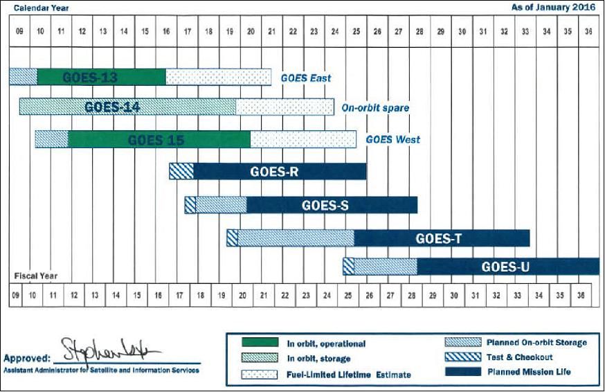
• Fall 2016: In geostationary orbit, NESDIS operates GOES-13 in the "GOES-East" position at 75° W and GOES-15 in the "GOES-West" position at 135° W. GOES-14 is available as an on-orbit spare, located at 105° W. NOAA's two operational GOES satellites provide consistent and reliable monitoring of the entire Western Hemisphere and are critical for identifying and tracking severe weather, snow storms, and tropical cyclones.
- GOES-East and GOES-West are providing data every 15 minutes to weather forecasters to support their forecasts and warnings. Although GOES-West experienced a component anomaly (i.e., loss of one of the two remaining star trackers) in April 2015, the satellite continues to operate on the single remaining star tracker and continues to meet all user performance requirements. The GOES-West Solar X-Ray Imager and X-Ray Sensor are acting as primary instruments, providing operational measurements, for NOAA's Space Weather Prediction Center. — In November 2015, the GOES-East sounder filter wheel stalled. However, the imager continues to operate normally and is meeting all essential NWS weather forecasting needs. The current on-orbit spare, GOES-14, is in normal configuration, instead of storage mode configuration, to provide quick services as a backup. GOES-14 has been periodically providing 1-minute Super Rapid Scan Operations to help algorithm developers, research partners, and forecasters prepare for the advanced capabilities available on the next-generation R-series geostationary satellites. All of the GOES-14 payload instruments are fully functioning without any performance degradation.
• On May 24, 2016, GOES-13 was 10 years on orbit. Known as GOES-N prior to launch, GOES-13 has been serving actively as GOES-East since April 2010. It was the first of NOAA's three-axis, body-stabilized geosynchronous environmental satellites and features a variety of enhanced instruments whose capabilities surpass those of earlier GOES satellites. Among them are: 15)
- An improved INR (Image Navigation and Registration) system that uses star trackers, optical devices that measures the position of the stars to help with spacecraft orientation, to provide more stable and accurate Earth-pointing capabilities, decreasing the amount of "shake" in an image.
- An imaging radiometer that uses data obtained from its five channels to continuously produce images of the Earth's surface, oceans, severe storm development, cloud cover, cloud temperature and height, surface temperature, and water vapor. It allows users to identify fog at night, distinguish between water and ice clouds during daytime hours, detect hot spots (such as volcanoes and forest fires), locate a hurricane eye, and acquire measurements of ground and sea surface temperatures.
- A sounder that provides detailed descriptions of conditions in the atmosphere at any time, allowing meteorologists to deduce atmospheric temperature and moisture profiles, surface and cloud-top temperatures, and ozone distributions. Sounder data is also used in computer models that produce mid-and long-range weather forecasts.
- A space environment monitor that consists of three components — an energetic particle sensor package, two magnetometer sensors, and a solar x-ray sensor — to keep tabs space weather conditions and provide warnings of geomagnetic storms capable of damaging communications and electrical infrastructure on Earth.
As part of the international COSPAS-Search and Rescue Satellite-Aided Tracking (SARSAT) system, GOES-13 carries a transponder that detects signals transmitted by 406 MHz emergency beacons used by planes, ocean-going vessels, and individuals in emergency situations and relays the location data to search and rescuers.
• GOES-15 is operational in 2015. In December 2011, GOES-15 was moved to 135ºW to replace GOES-11 as GOES-W.
• GOES-P (launch March 4, 2010): Twelve days after launch, GOES-P reached its geostationary orbit (from GTO) and was renamed to GOES-15. 16) 17)
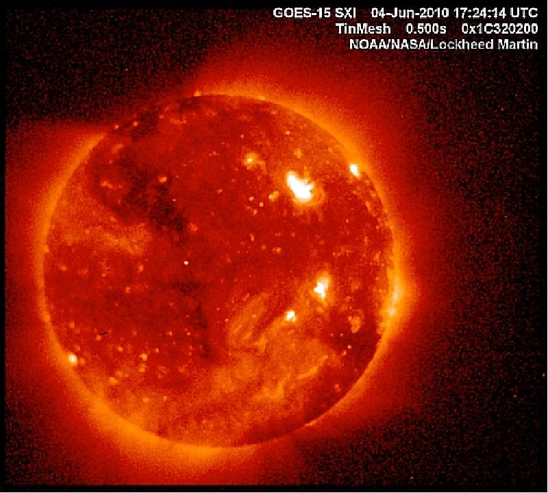
- On April 6, 2010, GOES-15 captured its first visible image of Earth and on April 26, GOES-15 took its first full-disk infrared image.
- The SXI (Solar X-ray Imager) on GOES-15 suffered a voltage glitch soon after achieving orbit in the early checkout phase. This anomaly required the repair team of NASA, NOAA, and LMSAL engineers to persue all avenues to recover the instrument. On June 3, 2010, SXI finally came on-line. The team had subjected SXI to a series of long duration turn on tests in the hopes of clearing the short. About 16 hours into the testing, the instrument voltages returned to normal values and SXI now appears to be functioning properly. 18)
- GOES-15 will complete its checkout period in August 2010 and be stored on-orbit at 105º W, ready for activation should one of the operational GOES satellites degrade or exhaust their fuel.
In 2010, the NOAA GOES system consists of: 19)
• GOES-13 became the official GOES-East satellite on April 14, 2010. GOES-13 was moved from on-orbit storage and into active duty. 20)
• In early Dec. 2009, NOAA deactivated GOES-10 after 12 years of service. The satellite was moved into a higher graveyard orbit. 21)
• GOES-10: In Dec. 2006 GOES-10 was positioned at 60º W longitude with an inclination of ~ 1º. Without the availability of station-keeping fuel, the inclination will continue to increase by about 0.95º per year. GOES-10 is providing regional coverage for South America and the Caribbean area. This represents a NOAA contribution to the EOPA (Earth Observation Partnership of the Americas) program on a best effort basis. 22)
NOAA replaced GOES-10 with GOES-11 as the operational GOES-W satellite in June of 2006 (135º W, inclination at 0.7º). However, GOES-10 is still functioning well, but has exhausted its north-south station-keeping fuel. GOES-10 completed its eastward drift from longitude 135º W to 60º W in early December 2006; it continues to operate as an XGOHI (Extended GOES High Inclination) satellite to provide coverage over South America. In Feb. 2009, the Sounder of GOES-10 stopped operating.
As the inclination rises, there are two effects that must be taken into account for operations. The first effect is the operational limit of the IMC (Image Motion Compensation) system. The current operating mode (IMC-On) entails small adjustment motions of the scan mirror to maintain the image-stability and co-registration. The limit of this system is approximately two degrees, which will be reached around July 2007. NOAA is in the process of developing a software enhancement to the Sensor Processing System (SPS) that will resample data taken in the IMC-Off mode to produce resampled GVAR (GOES Variable) data that appears (to the user) to be very similar to the IMC-On data we currently have and that can continue to be displayed by the current GVAR receiving systems.
• GOES-11: located at 135º W longitude and 0º inclination, is the operational West slot spacecraft. The SEM package is operating with degraded performance.
• GOES-12: located at 75º W longitude and 0º inclination, is the operational East slot spacecraft. The SEM package is operating with degraded performance. The SXI is not operational.
• The GOES-13 (formerly GOES-N) spacecraft, with a launch on May 24, 2006, was checked out after launch and placed in on-orbit storage on Jan. 5, 2007. GOES-13 is temporarily located at 105º W. It will remain in storage (standby) until either thruster fuel is depleted or instrument failure occurs on one of the two currently operational GOES satellites. As of June 2009, GOES-13 is still on orbit storage.
• The GOES-13 Imager and Sounder as well as the SXI instrument, transmitted their first images in Aug. 2006 when the checkout period started. GOES-13 met all of its INR requirements for normal operations during its checkout period.
• The GOES-14 spacecraft was placed into on-orbit storage in December 2009. The S/C was launched on June 27, 2009 and subsequently functionally tested and calibrated. NASA turned over the responsibility of the S/C to NOAA on Dec. 14, 2009. 23)
• For GOES-15, it will take ~ 5 months for all the instruments on board to be tested and calibrated. After that, GOES-15 will be a back-up satellite, stored on-orbit and ready for activation should one of the operational GOES satellites degrade or exhaust their fuel.
Sensor Complement
The sensor complement consists of government provided instruments to the prime contractor BSIS. The first three sets of Imagers and Sounders will be essentially the same as for the GOES I-M series. Imager channels remain the same as those on GOES-M, with a reduction in horizontal resolution from 8 km to 4 km in the 13.3 µm channel (TIR) on GOES-O and P. The Sounder instruments consist of the same filter-wheel based sounders as before.
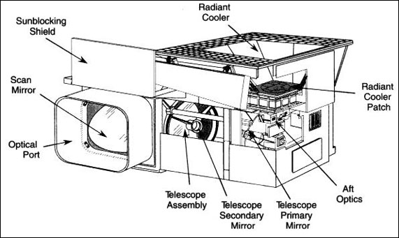
GOES Imager
The GOES Imager was designed and developed by ITT Industries Inc. (ITT-A/CD) of Fort Wayne, IN. The imager is a multispectral five-channel instrument that produces visible and infrared images of Earth's surface, oceans, cloud cover and severe storm developments. The Imager senses radiant energy and reflected solar energy from the Earth's surface and atmosphere. - The GOES-N/O/P Imagers will not have the 12-13 µm channel (a volcanic ash-sensitive channel which was converted to a cloud-sensing 13 - 13.7 µm channel on GOES-M). Note: GOES-O/P provides an improved 4 km resolution in the 13-13.7 µm channel. 24)
Band wavelength (µm) | Pixel size (km) | Primary objective of observations (products) |
0.52 - 0.71 (VIS) | 1 x 1 | Daytime cloud cover |
3.73 - 4.07 (MWIR) | 4 x 4 | Nighttime cloud cover |
5.80 - 7.30 (MWIR) | 4 x 4 | Water vapor |
10.20 - 11.20 (TIR) | 4 x 4 | Earth and cloud images; sea surface temperature and water vapor |
13.00 - 13.70 (TIR) | 8 x 8 on GOES-N; | Cloud cover and cloud height |
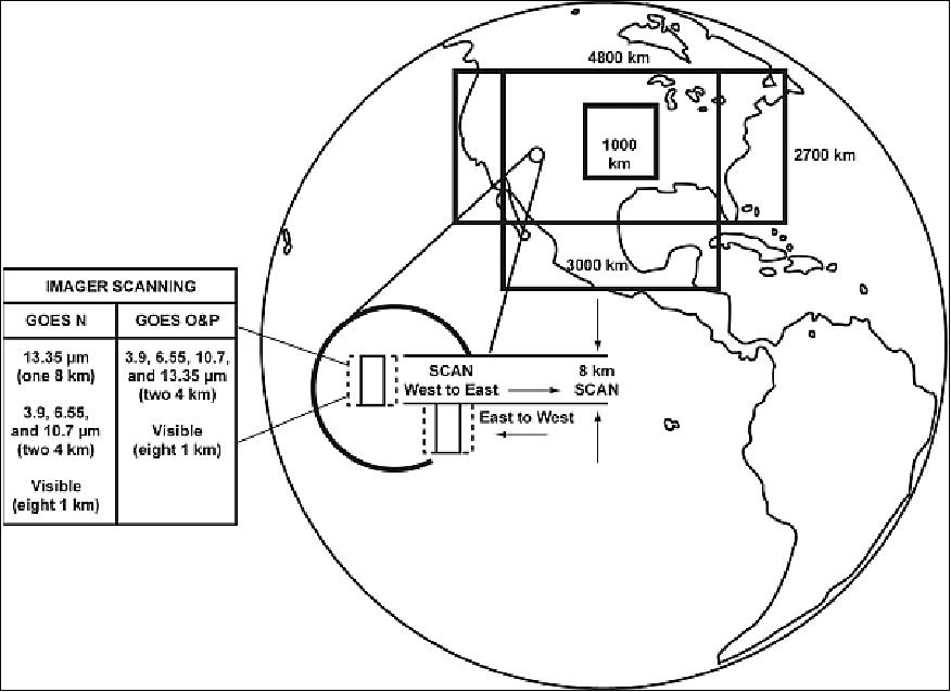
The GOES Imager simultaneously senses emitted thermal and reflected solar energy from selected areas of the Earth. It uses a scan mirror system to alternately sweep east to west and west to east perpendicular to a north-to-south path. The rate of scanning allows the instrument to gather data in its five spectral bands while stepping north-to-south from a 3,000 km x 3,000 km target area in three minutes, and from a target area of 1,000 km x 1,000 km in just 41 seconds.
GOES Sounder
The GOES Sounder was also designed and developed by ITT Industries Inc. The Sounder is a 19-channel discrete-filter radiometer, designed to sense the emitted thermal energy and reflected solar energy from sampled areas of the Earth's surface and atmosphere to provide data for computing vertical profiles of temperature and moisture, surface and cloud-top temperatures, and ozone distribution. The Sounder looks at conditions in "columns" of the atmosphere - cylindrical sections that extend from the Earth's surface to the upper reaches of the atmosphere.
The Sounder operates by means of a scan mirror that steps across the disk of the Earth in a west-to-east and east-to-west direction along a north-to-south path as the filter wheel rotates. The filter wheel has 18 filters, each of which corresponds to a particular band or wavelength in the electromagnetic spectrum. Each filter allows only energy with a particular wavelength to reach the detectors. All 18 filters and the visible band are sampled during each rotation, which occurs 10 times per second.

Observation range | Channel No | Center wavelength (µm) | Objective |
TIR (Thermal Infrared) | 1 | 14.71 | Temperature sounding |
MWIR (Midwave Infrared) | 10 | 7.43 | Water vapor |
SWIR (Shortwave Infrared) | 16 | 4.13 | Temperature sounding |
VIS (visible) | 19 | 0.70 | Cloud detection |
Feature | GOES Imager | GOES Sounder |
Optical aperture | 31.1 cm | 31.1 cm |
Telescope type | Cassegrain | Cassegrain |
Total step & sample time | N/A | 0.1 s (0.2 s and 0.4 s optional) |
Methods of scan | 2-axis, continuous, | 2-axis, step & dwell; E/W 280 µrad steps; N/S 1120 µrad steps (optional 2240 µrad steps, 0.2 s dwell) |
Scan rate | 20º/s optical | 40 soundings/s |
Slew rate | 10º/s mechanical | 10º/s mechanical |
Spatial resolution (µrad) | VIS = 28, Ch. 2,4, & 5 = 112, | all channels = 242 µrad (diameter) |
Sampling | 1.75/IGFOV VIS, Ch. 2, Ch. 4 & Ch. 5 3.5/IGFOV Ch. 3 | 4 IGFOVs sampled simultaneously |
Sampling rate | 183.3 µs/pixel (IR), | 0.1 s |
Chan. co-registration | ± 28 µrad | Within 22 µrad of channel 8 |
Star sensing | Uses visible array SNR 6 for 4th mag stars (400 samples) | Separate visible array SNR 6 for 4th mag stars (each sample) |
Data output | 10 bit quantization | 13 bit quantization |
Data rate | 2.6208 Mbit/s | 40 kbit/s |
Data format | NRZ-S, PN code | NRZ-S, PN code |
Patch temperature | Regulated at 94 K, 101 K or 104 K | Regulated at 94 K, 101 K or 104 K |
Time between space looks | 2.2 s large frame | 2 min |
Time between BB calibrations | 10-30 min (can override or inhibit) | 20 min (can override or inhibit) |
Priority frame select | 1 level normal; 2 levels priority | 1 level normal; 2 levels priority |
SEM (Space Environment Monitor)
The objective of the SEM package is to measure solar radiation in the X-ray and EUV (Extreme Ultraviolet) region and the in-situ magnetic field and energetic particle environment at geosynchronous orbit, providing real-time data to the NOAA(SEC (Space Environment Center). 25)
The SEM subsystem consists of multiple instruments used to monitor the near Earth (geostationary altitude) space environment and observe solar X-ray (XRS) and extreme ultraviolet (EUV) output.
- XRS/EUV instrument mounted on a positioning platform, fixed on the solar array yoke, observes solar output (measurement of disk-integrated solar X-ray and EUV fluxes).
- EPS (Energetic Particle Sensor) and the HEPAD (High Energy Proton and Alpha Detector) measure the flux of protons, alpha particles, and electrons over an extensive range of particle energies
- Two redundant three-axis magnetometers, mounted on a deployed 8.5 m boom, operate simultaneously to measure Earth's geomagnetic field strength and variations in the vicinity of the spacecraft.
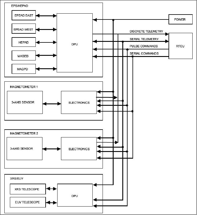
• The XRS/EUV sensor measures disk-integrated solar x-ray and EUV fluxes. The XRS/EUV consists of two channels in the X-ray sensor, five channels in the EUV sensor, and a DPU (Digital Processing Unit) that controls the instrument. The microprocessor based DPU supports both sensors, providing power, telemetry and command, and data processing (see Figure 14). The XRS design is based on an ion chamber design from previous (2nd generation) GOES spacecraft and the EUV sensor design is similar to one flown on the SOHO spacecraft. The sensor telescopes use magnetic shielding to reduce the background from high energy electrons, and the detectors are all well shielded from ambient particles and bremsstrahlung effect.
The XRS is an X-ray telescope that measures solar X-ray flux in two bands of 0.05 - 0.3 nm and 0.1- 0.8 nm. The XRS assembly consists of a telescope collimator, sweeper magnet assembly, dual ion chamber and preamplifier subassemblies. Two ion chambers detect X-rays, one chamber for each spectral range. The detector output signals are processed by separate electronic channels that have a single range in each band, with the >5 decade dynamic range logarithmically compressed into a 15 bit data word. Data transmitted through the spacecraft PCM telemetry permit real time ground determination of the solar X-ray emission in the two spectral bands.
The five-channel EUV telescope uses transmission gratings, filters, and solid state detectors to measure the extreme ultraviolet flux in five wavelength bands centered at 10 nm, 30 nm, 60 nm, 80 nm, and 126 nm respectively. The five EUV channels are mounted on three optical benches with channel pairs A-B and C-D sharing components such as gratings and front apertures. The A-B channel pair uses a 5000 line/mm transmission grating, and the C-D channel pair uses a 2500 line/mm transmission grating. The E channel uses a 1667 line/mm transmission grating and one Lyman Alpha Filter. A strong magnetic field sweeps out electrons below 4 MeV. Radiation shielding of detectors further reduces bremsstrahlung effects.
Spectral bands |
|
Threshold Sensitivity: |
|
Resolution: |
|
Noise | Mean signal equal to the standard deviation of the data over a 10 s interval |
Sampling rate: |
|
Wavelength response | ±5% |
Angular response: (Sensitivity varies less than 5%) |
|
Pointing determination accuracy with respect to sun center | ±2 arcmin |
Threshold flux, dynamic range | Threshold Flux | Dynamic Range |
XRS-A | 5x10⁻⁹ W/m2 | 10,000 |
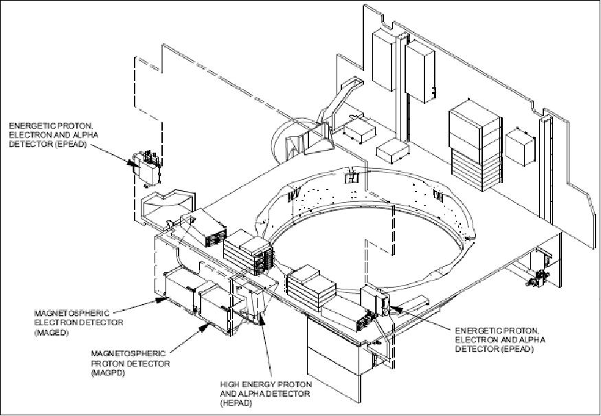
• The EPS/HEPAD instrument is partially based on the previous GOES EPS/HEPAD design for the measurement of medium and high energy protons, electrons, and alpha particles, that originate from the sun, are trapped in the magnetosphere, or are generated by cosmic rays deep in space. The complete EPS/HEPAD instrument consists of two energetic proton, electron, and alpha detectors (EPEADs), a magnetospheric proton detector (MAGPD), a magnetospheric electron detector (MAGED), a high energy proton and alpha detector (HEPAD), and a DPU that controls the five sensors and interfaces with the spacecraft.
Particle | Channel | Range (MeV) | Sample time (s) |
Proton | P1 | 0.74 - 4.2 | 8.2 |
Particle | Channel | Range (MeV) | Sample time (s) |
Proton | P4 | 15 - 40 | 32.8 |
• MAGPD and MAGED: Magnetospheric protons and electrons are measured at nine pitch angle directions using two detector sets (MAGPD and MAGED). The detector sets are mounted on the anti-Earth side of the spacecraft and measure protons or electrons at 0º, ±35°, and ±70º from the anti-Earth direction in both the equatorial and the azimuthal plane. Each detector telescope has a full detection cone angle of 30º.
The MAGPD (Magnetospheric Proton Detector) measures protons in five differential energy channels from 80-800 keV and is based on the SEM-2 MEPED instrument on the NOAA polar orbiting operational environmental spacecraft (POES). The MAGPD telescopes each have two SSDs (Solid State Detectors) that operate in an anticoincidence mode to provide the required proton channels. Sweeping magnets exclude electrons below several hundred keV.
The MAGED (Magnetospheric Electron Detector) measures electrons in five differential energy channels from 30-600 keV and is also based on the SEM-2 MEPED instrument on the POES spacecraft. Physically, the MAGED is very similar to the MAGPD, the only difference being the detector assemblies. The MAGED telescopes each use a single SSD with a foil light shield and do not have sweeping magnets. Algorithms are provided to correct the electron channels for the proton contamination that is unavoidable with this detection system.
Channel | Range (keV) | Sample time (s) |
MP1 | 80 - 100 | 16.4 |
Channel | Range (keV) | Sample time (s) |
ME1 | 30 - 50 | 2.0 |
• HEPAD (High Energy Proton Alpha Detector) is based on the instrument on the previous GOES spacecraft but modified to provide channel count accumulation within the HEPAD unit. The HEPAD interfaces with the DPU, which controls the HEPAD and formats the accumulated counts and housekeeping data for spacecraft telemetry. The instrument uses two SSDs in a telescope arrangement with a Cerenkov radiator/photomultiplier tube (PMT) detector to measure relativistic protons and alpha particles. A triple coincidence among these three detectors sends a particle detection signal, and the PMT measures the energy. The HEPAD measures protons with energies above 330 MeV and alpha particles with energies above 2.56 GeV.
Particle | Channel | Range (MeV) | Sample time (s) |
Proton | P8 | 330 - 420 | 32.8 |
• Magnetometers: There are two magnetometers on the spacecraft. Each magnetometer consists of a triaxial fluxgate sensor and an electronics unit. Each magnetometer measures three orthogonal vector components of the magnetic field in the vicinity of the spacecraft. The three magnetometer axes are orthogonal to within ±0.5º and have a linear range of ±512 nanoTesla (nT). The determination of the ambient magnetic field in the vicinity of the spacecraft is continuous and simultaneous.
The two three-axis magnetometers provide redundancy for measuring the geomagnetic field. One magnetometer is mounted at the end of the boom 8.5 meters away (outboard) from the spacecraft, and the second, 0.8 meters inboard from the first on the same boom. These large distances from the spacecraft significantly reduce magnetic effects from the spacecraft body.
Dynamic range | ±512 nT, ambient field in any orientation |
Resolution | 0.03 nT |
Accuracy | < ±4 nT without temperature correction |
Noise | ≤ 0.3 nT, 3σ |
Data rate | 1.95 Hz |
Bandwidth | 0.5 Hz, 3 dB |
Sensor axes orthogonality | Within ± 0.5º |
Sensor orientation | ≤ ±1.0º, in spacecraft coordinates (accuracy knowledge) |
Spacecraft field contamination (max permanent field per axis) | ± 100 nT |
Sensor stability | ±0.25º |
SXI (Solar X-ray Imager) - Part of the SEM Package
SXI (Solar X-ray Imager) was built by the Lockheed Martin Solar and Astrophysics Laboratory (LMSAL). The objective of SXI is to monitor the sun's X-rays for the early detection of solar flares. This early warning is important because these solar flares affect not only the safety of humans in high-altitude missions, such as the Space Shuttle, but also military and commercial satellite communications. 26) 27) 28)
The SXI instrument observes the sun in the soft X-rays broadband of 0.6-6.0 nm (or 6-60 Å). The instrument cannot be focused by transmissive optics or by "normal-incidence" mirrors. It is necessary to use grazing incidence mirrors, typically shaped like a cylinder, with the X-rays making one or more bounces at very shallow angles. The GOES-13 instrument uses a modified Wolter design with a single piece of glass fashioned into two sections. In a break with past designs, both sections have a hyperboloidal figure, which provides a flatter overall focus. Like all such optical systems, the GOES-N SXI design suffers from a geometric vignetting that increases linearly with displacement from image center. The magnitude of the vignetting approaches 13% for features lying 20 arcmin off-axis.
The SXI instrument employs thinned, back-illuminated CCD detectors. The detector provides a 5 arcsec pixel size and bandpasses of roughly 6 to 60 Å (corresponding to~0.2 to 2 keV). Image sequences are defined by sets of commandable tables.
The SXI CCD detector provides the following characteristics:
• 528 x 588 active pixel imaging area
• Back illuminated to maximize quantum efficiency in the low energy X-ray region
• 16 µm square pixels
• Anti blooming facility to improve the dynamic range by preventing charge spilling into adjacent pixels
• On-chip temperature sensors
• Two output amplifiers (for redundancy)
• Dump gate and drain for windowing.
The overall performance of the GOES-13 SXI is similar in spatial resolution to the Yohkoh SXT telescope in full-image mode. SXI provides continuous, near real-time observation of the sun's corona, acquiring a full-disk image every minute. The images cover a 42 arcmin FOV with five arcsec pixels.
Imaging exposure times: |
| ||
Spacecraft SXI boresight pointing (to center of solar disk) | Within 3 arcmin elevation, within 3.5 arcmin azimuth | ||
FOV (Field of View) | 42 arc min x 42 arcmin | ||
Pixel size | 5 arcsec x 5 arcsec, square pixels | ||
Spectral sensitivity (integration time 100 ms) |
| ||
Spectral band | Source | Minimum detectable photon radiance incident on the telescope entrance (photon cm-2 arcsec-2 sec-1) | |
6 to 20 Å | Cu (13.3 Å) | 85 | |
Dynamic range | 1000 when measured with monochromatic illumination at 44.7 Å | ||
Telemetry amplitude digitization | 12 bit (linear or logarithmic channels) | ||
Enpixeled energy | 13.3 Å (Cu) | 44.7 Å | |
On axis | 26% | 29% | |
10 arcmin off axis | 27% | 32% | |
20 arcmin off axis | 52% | 52% | |
Resolution (on axis) | 7 arcsec (full width half max) | ||
SXI on-orbit useful life | 3 years with a goal of 5 years (after 5 years ground storage) | ||

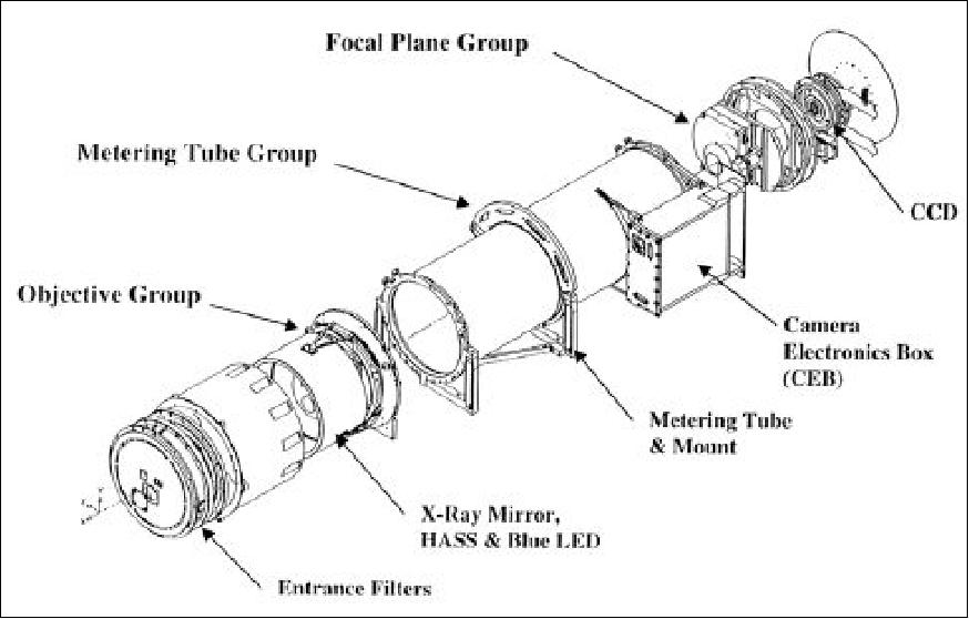
Telescope assembly: The telescope design consists of three basic groups: objective group, metering tube group, and focal plane group. The main components of the objective group are a hyperboloid-hyperboloid grazing incidence X-ray mirror, entrance filters, the HASS (High Accuracy Sun Sensor), and a mirror mounting structure. The metering tube group consists of a metering tube and its mount. The focal plane group components are a CCD detector, filter wheel assembly, and CCD radiator.
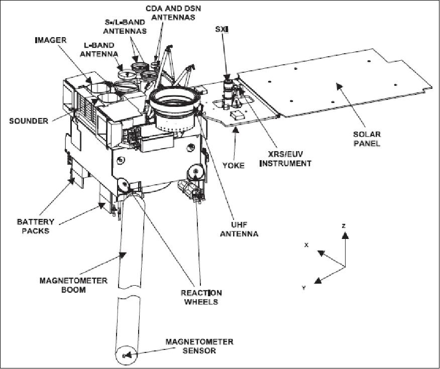
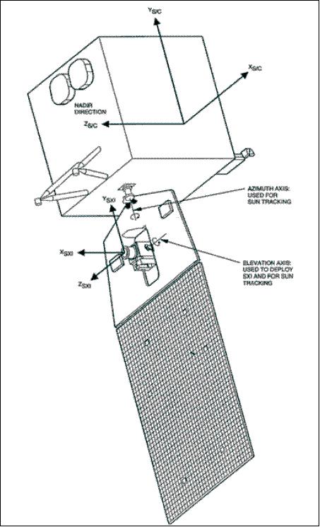
The SXI instrument is housed in the yoke assembly of the GOES-N spacecraft, as shown in Figure 17. The main body of the spacecraft points continuously at Earth, but the yoke assembly on which the solar array panels are mounted counter-rotates to face the sun at all times.
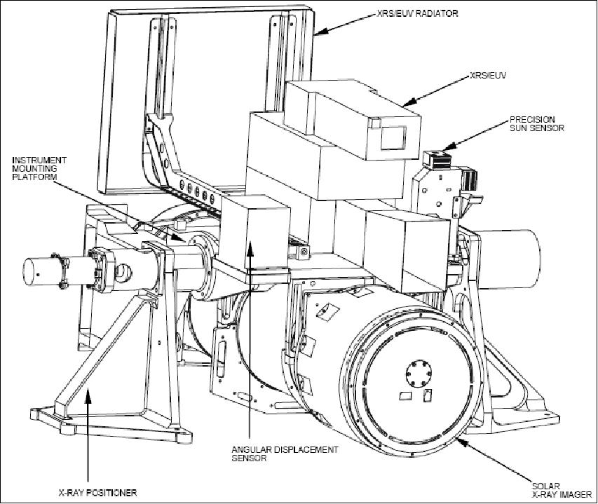
The SXI telescope, along with other solar observing sensors, is mounted on an instrument mounting platform (IMP). The SXI is coaligned on the IMP with the combined XRS/EUV (X-ray Sensor and Extreme Ultraviolet Radiometer) and the PSS (Precision Sun Sensor). The IMP is mounted to the XRP (X-ray Positioner). The complete assembly including the XRP is called the XRS/EUV/SXI assembly (Figure 14).
The XRP is a single-axis gimbal aligned in the north-south direction, tracking the sun in solar declination. The solar array drive (SAD) assembly controls the east-west pointing of the yoke, tracking the diurnal motion of the sun. Both the XRP N-S pointing and the yoke E-W pointing are controlled during routine observations by spacecraft-provided closed-loop control systems utilizing the two-axes of the PSS as aspect sensors.

DCS (Data Collection System)
The DCS has been enhanced to support 300 and 1200 bit/s DCPs (Data Collection Platforms) using 8-PSK modulation and a higher power satellite transponder so that more DCPs can use the link at the same time. See description under 2nd generation GOES.
References
1) http://www.boeing.com/defense-space/space/bss/about/about_text.html
2) http://goes.gsfc.nasa.gov/text/goesnopq.status.html
3) Vanessa L. Griffin, "OSPO (Office of Satellite and Product Operations) COPC Brief, Spring 2016, URL: http://www.ofcm.gov/groups/COPC/meetings/2016-01/03-OSPO%20COPC%202016%20draft%20ver4.7.3.pdf
4) "GOES-N,O/P/Q - The Next Generation," NASA Brochure, NP-2001-7-324-GSFC, URL: http://goespoes.gsfc.nasa.gov/goes_npbooklet/booklet.pdf
5) http://goespoes.gsfc.nasa.gov/goes/spacecraft/index.html
6) http://www.boeing.com/defense-space/space/bss/factsheets/601/goes_nopq/goes_nopq.html
7) GOES-N DataBook, April 26, 2006, URL: http://goes.gsfc.nasa.gov/text/goes.databookn.html
8) "GOES N Data Book," Rev B, February 2005, Copyright © 2006 Boeing, URL: http://goes.gsfc.nasa.gov/text/GOES-N_Databook/databook.pdf
9) C. Carson, J. L. Carr, C. Sayal, "GOES-13 end-to-end INR performance verification and post-launch testing," 5th GOES Users' Conference, January 22-23, 2008, New Orleans, LA, USA (part of the 88th AMS Annual Meeting ), URL: http://ams.confex.com/ams/pdfpapers/135921.pdf
10) James L. Carr, Bruce Gibbs, Houria Madani, Nate Al len, "INR Performance of the GOES-13 Spacecraft Measured in Orbit," Proceedings of the AAS Guidance and Control Conference, Breckenridge, CO, USA, Feb. 1-6, 2008, AAS 08-077
11) Y. A. Wu, R. K. Li, A. D. Robertson, "Precision Attitude Determination for GOES-N Satellite," Proceedings of the 26th AAS Conference on Guidance and Control, Breckenridge, CO, Feb. 5-9, 2003, Vol. 113 Advances in the Astronautical Sciences, Edited by I. J. Gravseth and R. D. Culp, AAS 03-002, pp. 21-38
12) http://goespoes.gsfc.nasa.gov/goes/spacecraft/n_p_spacecraft.html
13) http://noaasis.noaa.gov/LRIT/
14) Active CGMS members are: EUMETSAT (Europe), JMA (Japan), CMA (China), HYDROMET (Russia), NOAA (USA), and WMO. The global network of meteorological satellites constitutes a major portion of the space-based GOS (Global Observing System) of WWW (World Weather Watch).
15) "GOES-13 Turns 10," NESDIS News Archive, May 24, 2016, URL: http://www.nesdis.noaa.gov/news_archives/goes_13.html
16) "NASA and NOAA's Environmental Satellite Now GOES-15," March 19, 2010, URL: http://www.nasa.gov/centers/goddard/news/releases/2010/10-029.html
17) http://www.nasa.gov/mission_pages/GOES-P/main/index.html
18) "GOES-15 Solar X-Ray Imager's Miraculous First Light," June 14, 2010, URL: http://www.nasa.gov/mission_pages/GOES-P/news/xray_imager.html
19) http://www.oso.noaa.gov/goesstatus/
20) "GOES-13 is America's New GOES-EAST Satellite," NASA, April 16, 2010, URL: http://www.nasa.gov/mission_pages/goes-n/media/goes-east.html
21) "NOAA Deactivates GOES-10 After 12 Years Of Tracking Storms," Space Mart, Dec. 7, 2009, URL: http://www.spacemart.com/reports/NOAA_Deactivates_GOES_10_After_12_Years-Of_Tracking_Storms_999.html
22) "XGOHI, eXtended GOES High Inclination Mission," April 4, 2007, URL: http://www.oso.noaa.gov/seminars/docs/XGOHI-Presentation-04-04-07.pdf
23) "GOES-14 (O) Moving into On-Orbit Storage Around the Earth," NASA, Nov. 30, 2009, URL: http://www.nasa.gov/mission_pages/GOES-O/news/orbit_storage.html
24) http://goes.gsfc.nasa.gov/text/GOES-N_Databook/section03.pdf
25) http://goes.gsfc.nasa.gov/text/GOES-N_Databook/section05.pdf
26) http://www.lockheedmartin.com/news/press_releases/2005/LOCKHEEDMARTIN-SOLARXRAYIMAGERBELAUN.html
27) "Solar X-Ray Imager," Feb. 2005, URL: .http://rsd.gsfc.nasa.gov/goes/text/GOES-N_Databook/section06.pdf
28) http://www.mssl.ucl.ac.uk/www_detector/sxi/SXIintro.html
The information compiled and edited in this article was provided by Herbert J. Kramer from his documentation of: "Observation of the Earth and Its Environment: Survey of Missions and Sensors" (Springer Verlag) as well as many other sources after the publication of the 4th edition in 2002. - Comments and corrections to this article are always welcome for further updates (eoportal@symbios.space).
Spacecraft Launch Operational Status Sensor Complement References Back to Top