Hodoyoshi-3 and -4 ('Reasonably Reliable Systems', in Japanese, 3 and 4)
EO
Ocean
Multi-purpose imagery (ocean)
Ocean imagery and water leaving spectral radiance
Quick facts
Overview
| Mission type | EO |
| Agency | ISSL UT |
| Mission status | Operational (nominal) |
| Launch date | 19 Jun 2014 |
| Measurement domain | Ocean, Land |
| Measurement category | Multi-purpose imagery (ocean), Multi-purpose imagery (land), Landscape topography, Lightning Detection |
| Measurement detailed | Ocean imagery and water leaving spectral radiance, Land surface imagery, Fire fractional cover, Land cover, Land surface topography, Snow cover, Sea level, Soil type, Glacier topography, Visibility, Surface Coherent Change Detection, Snow detection (mask) |
| Instruments | High Resolution Optical Sensor |
| Instrument type | High resolution optical imagers, Other, Communications, Data collection, Lightning sensors |
| CEOS EO Handbook | See Hodoyoshi-3 and -4 ('Reasonably Reliable Systems', in Japanese, 3 and 4) summary |
Hodoyoshi-3 and -4 ('Reasonably Reliable Systems', in Japanese, 3 and 4)
High Rate Communications From a Microsatellite
Overview Spacecraft Launch Mission Status Sensor Complement Communications Sytem Ground Segment References
The Hodoyoshi-3 and -4 microsatellites were developed by the University of Tokyo (UT) under the FIRST (Funding Program for World-Leading Innovative R&D on Science and Technology) program of the Japanese Government.
The University of Tokyo and NESTRA (Next Generation Space system Technology Research Association) have been developing the 50 kg class twin-satellites, H3 and H4, since 2011 to demonstrate and establish an innovative system design and a cost-effective development process (e.g., integration, test, and operation) for mass-production of microsatellites in the future. 1) 2)
The primary mission of H3 and H4 is Earth observation by using various optical sensors. H3 has two different cameras which are low- and mid-resolution with a GSD (Ground Sampling Distance) of 250 m and 40 m; on the other hand, H4 has one relatively high-resolution camera with a GSD of 6-10 m. Furthermore, the satellites have various secondary mission instruments, for example, wide-angle minicameras, hosted payload boxes, technology demonstration module and materials, UHF data receiving system for a Store and Forward mission, in order to provide opportunities for rapid new technology demonstration on orbit and low-cost commercial usage like advertisement in space.
| Parameter | Hodoyoshi-3 (H3) | Hodoyoshi-4 (H4) |
Bus | Spacecraft size | 0.5 x 0.5 x H:0.7 m | 0.5 x 0.6 x H:0.8 m |
Spacecraft mass | 56 kg (including H2O2) | 64 kg (including Xe gas) | |
Thermal structure | Al-alloy honeycomb panel and isogrid base plate | ||
AOCS (Attitude and Orbit Control Subsystem) | Sun pointing Mode ⇔ Earth pointing Mode | ||
EPS (Electrical Power Subsystem) | Generation: max 130W (GaInP2/GaGa/Ge solar cell) | ||
C&DH (Command and Data Handling) | OBC: Advanced On-board computers (OBCs) for MOBC (Main Data Handing) | ||
Propulsion Subsystem | Monopropellant H2O2 | Xe Micro Ion Propulsion | |
RF Communications | S-band TT&C, CCSDS: | S-band TT&C, CCSDS: | |
Technology Demonstration | • New Batteries | • New Materials | |
Payloads | Main Imager | - MCAM (Medium-resolution Camera) | HCAM (High-resolution Camera) |
Sub-Imager | - VGA mini-camera | - VGA mini-camera | |
Spacecraft
Hodoyoshi-3:
The Hodoyoshi-3 is 0.5 m x 0.5 m 0.65 m in size with a mass of 56 kg. The spacecraft is equipped with body mounted solar cells and two deployable solar panels to deliver a maximum power of ~100 W that is distributed using a 28 V and a 5 V power bus. Power is stored in a 5.8Ah Li-ion battery and the expected average power consumption of all satellite subsystems is 50 W. 3)
The satellite is three-axis stabilized using star trackers, an inertial measurement unit and a reaction wheel assembly to provide very accurate Earth pointing capabilities. The telemetry downlink and command uplink is accomplished via an S-band system with an uplink rate of 4 kbit/s and a downlink rate of 4 to 64 kbit/s. The mission data is downlinked via an X-band system achieving data rates of up to 10 Mbit/s. The Hodoyoshi-3 satellite is outfitted with a hydrogen peroxide propulsion system for orbital maneuvers and orbit maintenance.
Hodoyoshi-3 is equipped with a LCAM (Low-resolution Camera) that can achieve ground resolutions of 200 m along a ground swath of 490 km and a MCAM (Medium-resolution Camera) that can reach a ground resolution of 40 m on a swath width of 82 km. 4) 5)
Hodoyoshi-4:
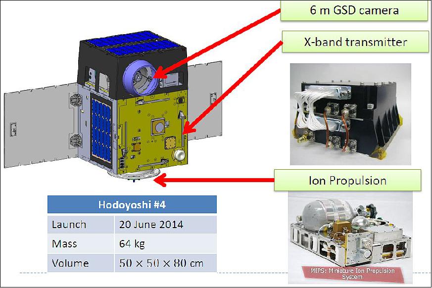
The Hodoyoshi-4 microsatellite is 0.5 m x 0.5 m x 0.8 m in size with a mass of 64 kg. It uses body-mounted solar panels and two deployable panels to generate ~100 W of power. The spacecraft is 3-axis stabilized and Earth pointing. Satellite stabilization is accomplished with star tracker data and reaction wheels. Communications are done in S-band for TT&C, like on Hodoyoshi-3; the Hodoyoshi-4 satellite uses an improved X-band system to demonstrate data rates of up to several 100 Mbit/s.

The Hodoyoshi-4 satellite is equipped with a Xenon-fueled ion-thruster for propulsion achieving thrust of 260 mN and a specific impulse of 1170 seconds. The system has a mass of 6 kg and a size of 39 x 28 x 16 cm and includes a Xenon tank with a capacity of about 1 kg. The propulsion system can deliver a total ΔV of 240 m/s requiring a peak power of 30 W.
The Hodoyoshi-4 microsatellite is also demonstrating an Earth observation payload. This high-resolution optical imager uses a pushbroom sensor to acquire Earth imagery at a ground resolution of 5 m. The system has a mass of 3.5 kg with an aperture diameter of 15 cm and a focal length of 10 cm. The imaging payload covers four spectral bands – Blue (450-520 nm), Green (520-600 nm), Red (630-690 nm) and Near-Infrared (730-900 nm). The observable ground swath is 30 km.
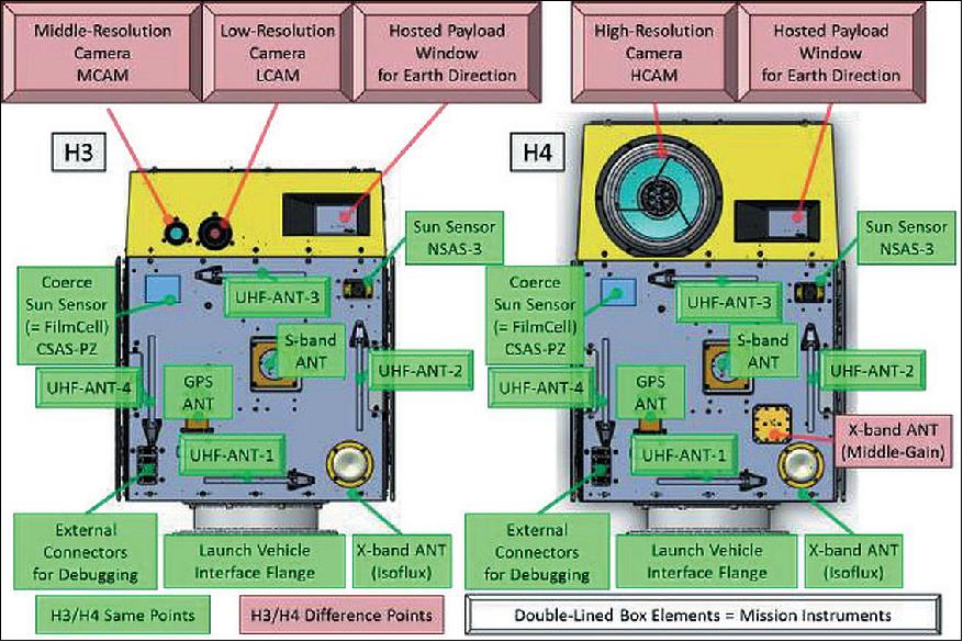
Figures 2 and 3 show the comparison of characteristics of H3 and H4, the spacecraft Earth pointing surface (defined as the PZ-Surface) and the SAP (Solar cell Array Paddle) surface (defined as the MZ-Surface). The remarkable difference between H3 and H4 appears to be the layout of equipment on PZ-Surface. Major mission instruments are located on this surface like the aperture of the observation camera and antenna. Hence, the PZ-Surface is usually kept facing into the nadir direction during observations, like image shooting and antenna pointing, for high-rate telecommunication in X-band downlink. This mode is defined as "Earth pointing mode." On the other hand, the MZ-Surface usually faces to the sun, because the largest number of solar cells are located (total: 140 cells) on this side - after SAP deployment.
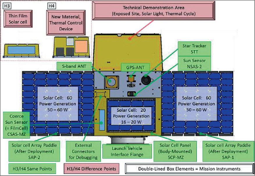
Figure 3 shows the real features of the SAP surface. This surface is almost similar between H3 and H4. As shown in Figure 3, the density of solar cell mounting on SAP is maximized for effective power generation. During house-keeping operation like battery charging, the MZ-Surface is kept facing into sun direction to keep enough power generation. This mode is defined as "Sun pointing mode."
The two major two attitude modes are realized by 3-axis control, using reaction wheels (RWs). Corresponding to the required control accuracy, each mode has a coarse state and fine state. Prior to achieving 3-axis stabilization in the initial operational phase, the satellite attitude is controlled by magnetic torquers (MTQs). Attitude control is provided according to the following modes:
- B-dot mode for reducing the tumbling rate
- Spin sun-pointing mode for controlling the spin rate about the Z-axis of spacecraft and pointing that spin axis to the sun.
Since the power consumption of the MTQs is lower than the 3-axis mode of the RWs, these modes can be executed under the tumbling condition. Therefore, these modes using MTQs are also used for recovery from attitude anomaly. Fundamentally, the mode transition is executed by an uplink command.
Launch
The Hodoyoshi-3 and -4 microsatellites were launched on June 19, 2014 as secondary payloads on a Dnepr-1 vehicle of ISC Kosmotras. The launch site was the Yasny Cosmodrome in the Dombarovsky region of Russia.
The primary payloads on this flight were the Deimos-2 minisatellite of Deimos Imaging S.L.U., Spain, with a mass of ~310 kg and the KazEOSat-2 minisatellite (~185 kg) of KGS, Kazakhstan.
The secondary payloads (35) on this Dnepr cluster mission were (Ref. 3):
• UNISat-6, a microsatellite of GAUSS at the University of Rome (La Sapienza), Italy. UniSat-6 (26 kg) includes Pico-Orbital Deployers and PEPPODs (Planted Elementary Platform for Picosatellite Orbital Deployment) systems for the release of four CubeSats from the spacecraft. These four satellites are:
- Lemur-1, a 3U CubeSat (technology demonstration and EO) of NanoSatisfi Inc., San Francisco, CA, USA
- TigriSat, a 3U CubeSat of the University of Rome (La Sapienza), Rome, Italy.
- ANTELSAT, a 2U CubeSat of UdelaR (University of the Republic), San Marino, Uruguay
- AeroCube-6, a 1U CubeSat of The Aerospace Corporation, El Segundo, CA.
• SaudiSat-4 a microsatellite (112 kg) of KACST (King Abdulaziz City for Science and Technology) with input from NASA/ARC.
• AprizeSat-9 and -10, nanosatellites (each of 12 kg) of SpaceQuest, USA. AprizeSat-10 carries an AIS (Automatic Identification System) receiver for ship tracking.
• Hodoyoshi-3 and -4, microsatellites (60 kg and 65 kg, respectively) of the University of Tokyo and JAXA/ISAS, Japan
• BRITE-CA-1 and BRITE-CA-2, two nanosatellites (7 kg each) of UTIAS/SFL (University of Toronto, Institute for Aerospace Studies), Toronto, Canada
• TabletSat-Aurora, a microsatellite (25 kg) of SPUTNIX, Russia
• BugSat-1, a microsatellite (22 kg) of Satellogic S.A., Argentina
• Perseus-M1 and M2, two identical 6U CubeSats of Canopus Systems US / Dauria Aerospace. The nanosatellites are carrying an AIS payload for ship tracking.
• QB50P1 and QB50P2, two 2U CubeSats (2 kg each) of Von Karman Institute, Brussels, Belgium. These are two precursor satellites to the QB50 project that will launch a network of 50 satellites by a team of 15 universities and institutions around the world.
• NanoSatC-Br1, a 1U CubeSat of the Southern Regional Space Research Center and of INPE, Brazil
• DTUSat-2, a 1U CubeSat of DTU (Technical University of Denmark), Lyngby, Denmark
• POPSat-HIP-1, a 3U CubeSat of Microspace Rapid Pte Ltd., Singapore
• PolyITAN-1 of KPI (Kiev Polytechnic Institute), Kiev, Ukraine
• PACE (Platform for Attitude Control Experiments), a 2U CubeSat (2 kg) of NCKU (National Cheng Kung University), Tainan City, Taiwan
• Duchifat-1, a 1U CubeSat of HSC (Herzliya Science Center), Israel
• 11 Flock-1c nanosatellites (eleven 3U CubeSats, 5 kg each) of Planet Labs, San Francisco, CA.
Orbit
Sun-synchronous orbit, nominal altitude of 630 km, inclination = 97.97º, LTAN (Local Time of Ascending Node) of 10:30 hours.
Mission Status
• In July 2015, the two microsatellites, Hodoyoshi-3 and -4 and their payload are operating nominally. The ion propulsion system has not been used so far; hence, the distance between two satellites is not keeping constant. 6)
• On June 19, 2015, the Hodoyoshi-3/-4 mission was 1 year on orbit, operating nominally.
• In February 2015, the University of Tokyo published the "record downlink event of 348 Mbit/s of a microsatellite" in a press release. 7)
• In December 2014, the 3.8 m antenna station at the ISAS campus Sagamihara received 348 Mbit/s data of the Hodoyoshi-4 microsatellite with 16 QAM modulation and successfully demodulated/decoded them without error. This communication speed is as high as a half of one of ALOS-2/Daichi-2, a Japanese Earth observation satellite with about 2 tons mass and is the world fastest as a 50 kg class small satellite. This result indicates that the capability of data transmission from a small satellite approaches to capability of a large satellite (Ref. 16). 8)
- The project performed high speed downlink experiments with 16 QAM : 100 Msps for 237 Mbit/s (ACM13) and 348 Mbit/s (ACM17). The MGA (Medium Gain Antenna, 13.5 dBi, beam width of 20º) was utilized to satisfy its communication link.
- The communication rate of 348 Mbit/s is currently the world record for a microsatellite in the 60 kg class. Soon, plans call for testing the 64 APSK modulation with a data rate of 500 Mbit/s.
- At the time of the downlink experiment, the satellite was not ready yet for this attitude operation. Instead the project performed high speed data downlink experiments when the satellite passed at elevation >70º in Earth-pointing attitude mode. In this condition, the Earth station is inside a half beam width of the onboard antenna. The transmitter sent repeatedly a fixed known data (PN code). The received signals were demodulated and decoded by the software receiver. Figure 6 shows the I-Q constellation diagram of received signals. The estimated received C/No based on received IF spectrum is about 96 dB Hz at ground antenna elevation angle of 84.5º and slant range of 622 km. The measured bit error rate is 1.2 x 10⁻³ without error correction. After the turbo decoding process, the measured bit error rate is less than 1.7 x 10⁻⁹.
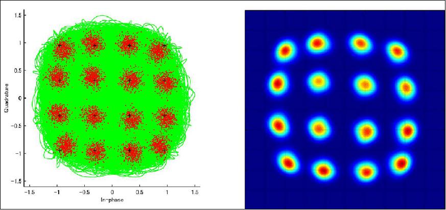

Figure 7 indicates downlink data rates of LEO (Low Earth Orbiting) satellites as a function of satellite mass. The figure shows that the downlink data rates are proportional roughly to linear or square of the satellite mass. This is because in general a down link with a high data rate requires high power consumption and consequently also a large mass.
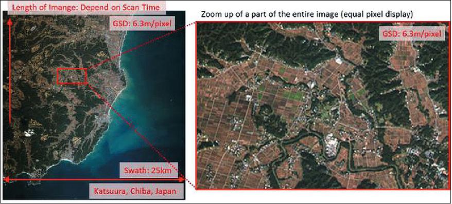


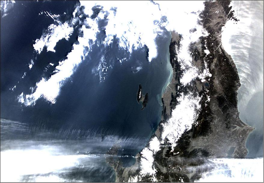
• August 1, 2014: First light of the HCAM (Figure 9).
• July 5, 2014: First light of the LCAM and MCAM (images acquired).
• July 4, 2014: Three-axis Earth pointing was achieved by the two satellites.
• July 2, 2014: Three-axis sun pointing was achieved by the two satellites.
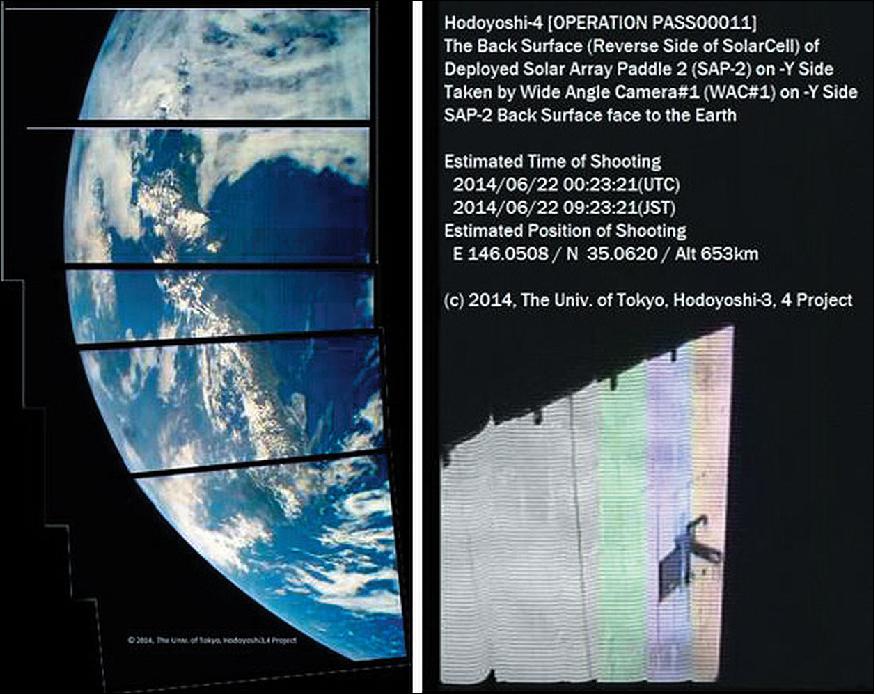
• June 22, 2014: First light of the wide-angle small camera, image and movie.
• June 20, 2014: The project had contact with the two satellites on the 1st and 4th passes over the ground station, verifying the deployment of the solar paddles and a sun-pointing spin mode (Ref. 1). 11)
Sensor Complement
HCAM (High-resolution Camera)
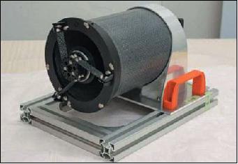
HCAM was developed by UT (University of Tokyo) and NESTRA (Next Generation Space system Technology Research Association), along with experienced companies. The optical system of HCAM features a Ritchey-Chretien type reflecting telescope with an aperture diameter of 150 mm and a focal length of 1000 mm. The primary mirror of HCAM is made of glass-ceramic material, and the lens barrel is made of CFRP (Carbon Fiber Reinforced Polymer). These materials is relatively light-weight and robust for dynamic changes in thermal conditions.
HCAM features a pushbroom type multi-spectrum sensor, consisting of 4 bands (R, G, B, and NIR). The HCAM imager has two identical NIR line sensors which are able to set gain parameter individually, so that its dynamic range can be expanded. A SpaceWire communication interface is implemented between HCAM and the SHU (Science data Handling Unit).
Sensor type | Pushbroom |
Aperture diameter | 150 mm |
Focal length | 1000 mm |
FOV (Field of View) | 2.35º |
GSD (Ground Sample distance) at 630 km altitude | 6.3 m |
Swath width @ 630km | 25.8 km |
Spectral band (S/N ratio in case of Zenith angle 30º, albedo 50%) | B1: 450 - 520 nm (77) |
Instrument mass | 5.2 kg (optical instrument), 0.65 kg (electric instrument) |
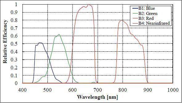
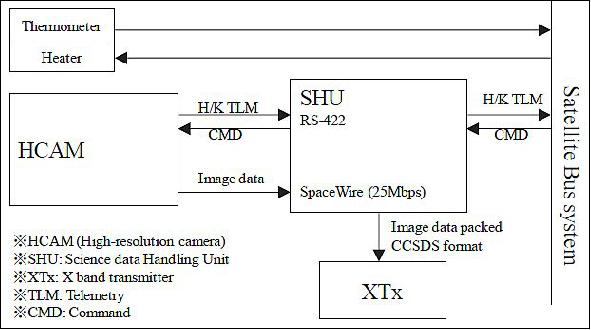
HCAM does not have on-board calibration equipment, and its sensitivity was not calibrated before flight. Therefore, the sensitivity characteristic was evaluated by desert image.
MCAM (Medium-resolution Camera) and LCAM (Low-resolution Camera)
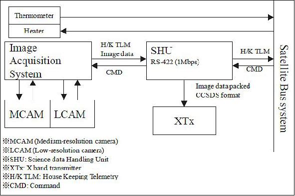
These two camera systems were developed by Tokyo University of Science and The University of Tokyo. The lens, imager IC, data handling unit of MCAM/LCAM consist mainly of COTS devices. The cameras feature a general RGB (Red-Green-Blue) Bayer type image sensor. In the case of MCAM, a multiband pass filter is mounted in front of the aperture of the imager so that 3-band (G: 550-580 nm, R: 650-690 nm, NIR: 890-930 nm) spectroscopic imaging can be performed. For LCAM, an IR cut filter is mounted. Data processing of MCAM and LCAM is performed by a FPGA board (OS: LINUX, image processing: OpenGL). MCAM and LCAM of H3 are able to provide the big picture of target phenomena of a specific region. This characteristic is applied for disaster monitoring, and environmental monitoring (broad area to middle-range area).
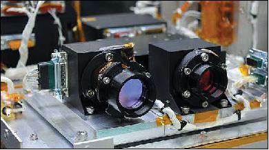
Parameter | MCAM | LCAM |
GSD @ 630 km | 40.3 m | 252 m |
Coverage area @ 630 km | 82.5 km x 61.9 km | 516 km x 387 km |
Spectral bands | G: 550 - 580 nm | RGB color |
Data quantization | 10 bit | 10 bit |
Image size | 2048 x 1536 pixels | 2048 x 1536 pixels |
FOV (Field of View) | 7.5º | 44.5º |
Instrument mass | 250 g | 190 g |
DCS (Data Collection System) Experiment
A DCS, also referred to as S&F (Store and Forward) system, is installed on H3 and on H4. The objective is to collect data from the ground segment. An identical UHF receiver on each microsatellite acquires the signals from the ground segment, performs an A/D conversion and stores the data onboard. The demodulation demodulation process is performed by software. Each DCS can provide communication only about 30 minutes a day.
The external view and specifications of the S&F demonstration experiment for the receiver U-DPD (UHF -Data Packet Decoder) are shown in Figure 17, and Table 4, respectively.
After the U-DPD receives the DPD (Data Packet Decoder) identification code, it down-converts the received RF signal to zero frequency, and starts the high-speed A/D conversion. The A/D converted values are recorded in the U-DPD mounted flash memory together with the data transmitted from ground transmitters including noise. The demodulation is performed by software to permit the weak signal demodulation buried in the noise.

Instrument size, mass | 150 mm x 150 mm x 35 mm, < 1 kg |
Power consumption | 5 W |
Frequency band | UHF (400 MHz) |
Storage capacity | 16 Gbit |
Sampling frequency | 10 kHz or 40 kHz |
Recording time | 1 s or 10 s |
Reception level | -120 dBm |
An inverted L-type 4-element array antenna is used for the on-board UHF antenna. Four UHF antennas are mounted on the Earth-oriented surface of Hodoyoshi 3 & 4. The maximum antenna gain is 4 dBm for the four antennas.
In the DCS/S&R experiment, UHF radio signals were transmitted from the ground transmitter, located in Choshi, Chiba, which were acquired by the satellite receiver. Tests were conducted under different conditions such as high (close to the zenith) or low (close to the horizon) elevation angles to make sure the transmitted data were successfully received. When the satellite elevation is larger than 37º, successful data transmission was confirmed.
MIPS (Miniature Ion Propulsion System)
The MIPS device was developed by UT and NESTRA. Ion thrusters are promising propulsion devices for small satellites to provide high ΔV maneuvers. They have the characteristics of high specific impulse, high thrust efficiency, and usage of inert propellant (xenon) . In spite of these benefits, however, miniature ion thrusters have not been employed on small spacecraft yet. This has been mainly impeded by two reasons: limitation of electrical power available on small spacecraft and difficulty to develop a miniature neutralizer suitable for a miniature ion thruster. 12) 13)
MIPS was developed using an ECR (Electron Cyclotron Resonance) plasma of a 4.2 GHz microwave system. The ECR plasma provides advantages of longer lifetimes and a simpler structure for ion thrusters. These features are suitable for the down-scaling of ion thrusters. However, the down-scaling of plasma inherently leads to high ion production cost. This problem was solved by a new antenna design for a small-sized cavity, and a small plasma source with low ion-production-cost was developed for microwaves as low as 1.0 W. This technique enabled a miniature ion source and a miniature electron source, neutralizer, driven by a 1.0 W microwave power source, respectively, resulting in a miniature and low-power ion thruster.
The MIPS consists of four units: an ITU (Ion Thruster Unit), a PPU (Power Processing Unit), a GMU (Gas Management Unit), and a MCU (MIPS Control Unit). A simplified block diagram of the system is shown in Figure 18. All of the units are installed on a double-deck frame , and MIPS is handled as a modularized component to a satellite.
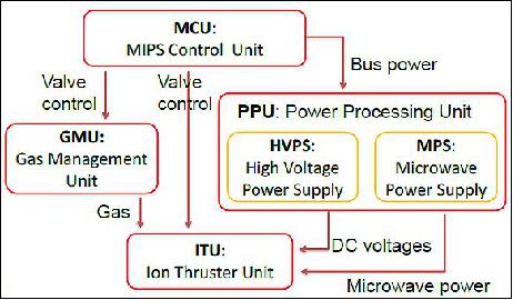
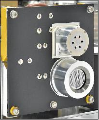
The ITU consists of an ion beam source, a neutralizer, a thruster valve, a gas distributor, a gas isolator, and DC-blocks. The ion beam source and the neutralizer have ECR plasma sources driven by microwave injection respectively and both sources have almost identical design. Both plasmas need the same amount of microwave power, typically 1.0 W each other. The ion beam source uses a two-grid system to accelerate and exhaust ions. The neutralizer employs a six-holed orifice, instead of the grid system, for electron emission. In contrast to the microwave power, lower gas conductance of the neutralizer orifice causes the half gas flow rate of the neutralizer compared with the ion beam source. The engineering/flight model of the ITU (ITU-EM/FM) was designed based on a laboratory-model thruster. The modification is to miniaturize the grid system. The assembled ITU is shown in Figure 19.
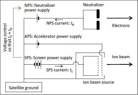
Applying three types of DC voltages to the ITU generates thrust by ion beam exhaust and its neutralization by electrons. The three voltages are provided by a SPS (Screen Power Supply), an APS (Accelerator Power Supply), and a NPS (Neutralizer Power Supply). Electrical connections of those supplies are shown in Figure 20.
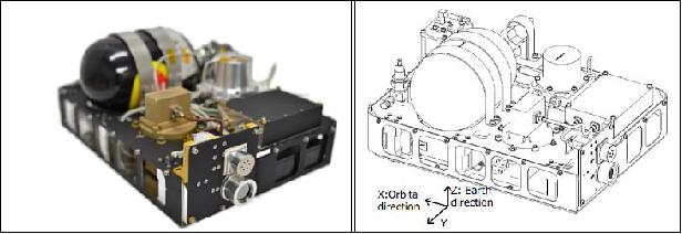
MIPS FM (Flight Model): All of the tests of the MIPS-EM ended in March 2013 and development of the flight model started in August 2013. Major modifications from the MIPS-EM to MIPS-FM are listed below:
1) Adding a low pressure sensor to increase the redundancy of mass flow control.
2) Packaging two pressure sensors, a drain valve, and a regulation vale in the low pressure tank.
3) Decreasing the microwave power of the MPS to reduce the power consumption of the system.
4) Painting the surface of the components black by Aeroglaze® Z306 for thermal radiation.
5) Exchanging the mechanical regulator to Swagelok® HF series, in which reference gas for the regulation is sealed inside the body.
Instrument size | 34 cm x 26 cm x 16 cm |
Instrument wet mass | 8.1 kg (inclusive 0.9 kg xenon) |
Power dissipation | 39 W |
Thrust | 210 µN |
Specific impulse | 740 s |
Delta-V for a 50 kg satellite | 140 m/s |
Communications sytem
Introduction of High-Speed Communication in Microsatellites
Hodoyoshi-4 is a microsatellite of JAXA/ISAS (Japan Aerospace Exploration Agency/Institute of Space and Astronautical Science) at the University of Tokyo. An important objective is to develop a novel high-speed communications system for 320 Mbit/s downlink transmissions with 16 QAM (Quadrature Amplitude Modulation) for microsatellites in the 60 kg class.
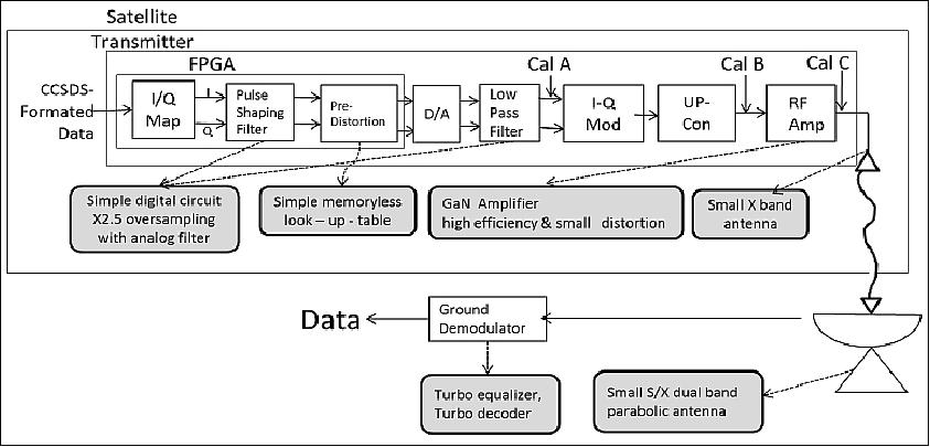
Japanese institutions/companies (referred to as the Hodoyoshi consortium) have already developed a new GaN/HEMT (Gallium Nitride/High Electron Mobility Transistor) X-band amplifier with high efficiency and small distortion, digital filter and pre-distortion processing with relatively low clock frequency in FPGA technology, and small X-band on-board antennas. In addition, a ground segment is under development consisting of a compact S/X dual band ground antenna station and a high performance demodulator with turbo equalizer/decoder based on CCSDS high rate telemetry standard. These technologies will be demonstrated in 2014 by the Japanese Hodoyoshi-4 microsatellite with a mass of ~64 kg. 14) 15) 16)
Today's EO (Earth Observation) spaceborne missions such as optical imaging and SAR imaging require higher spatial resolutions resulting in considerably higher data volumes. A cost-effective approach to increase the downlink data rate to a ground station which has short contact periods of around 6-10 minutes during the spacecraft passes.
Several improvements of conventional high rate downlink communications for microsatellites are proposed including a modulation scheme, an onboard RF amplifier and a transmitter, onboard small antennas, a small S/X dual-band ground station, and a high performance demodulator - illustrated in Figure 22 and Table 6.
| Instrument | Mass | Power | Comment/description |
Transmitter | 1.330 kg | 18 W | 16 QAM, 348 Mbit/s, GaN Power Amplifier | |
MGA (Medium Gain Antenna) | 69 g | 0 | 13.5 dBi | |
Ground station | Antenna | 3.8 m ∅ S/X Cassegrain, 47.5 dBi(X); 36 dBi(S), System noise temperature 100 K | ||
Demodulator | 100 K 100Msample/s, (348-144 Mbit/s), 16 QAM, QPSK | |||
The conventional communication systems of large satellites have the capability of hundreds Mbit/s through 1Gbit/s and in most cases they utilize the X-band (8025-8400 MHz) for Earth observation. The maximum bandwidth is 375MHz and in most cases a convolution coding with r=1/2 is applied. Therefore, multi phase-shift-keying and amplitude-phase modulation are necessary to achieve higher bit rates than 300 Mbit/s (Ref. 8).
These modulations, however, are sensitive to nonlinear distortion of RF power amplifiers. RF power amplifiers have to operate in linear region, which causes a reduction of power efficiency. Also, they require digital processing circuits with several hundred MHz of clock rate. Space-qualified devices for these purposes require high power consumption, high cost, and special care for ball grid array (BGA) devices.
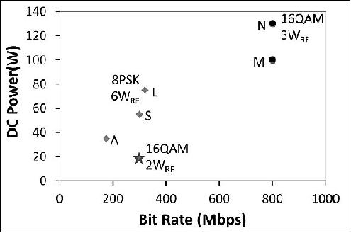
Figure 23 shows power consumptions as a function of data bit rate for onboard X-band transmitters with high data rates. Their power consumptions increase as the data bit rates increase with bandwidth-effective modulations. The conventional high data rate communication system of large satellite requires 100 W or 200 W as a whole for DC power consumption.
Several improvements for a high data rate downlink system as illustrated in Figure 22 are described, including a modulation scheme, an onboard RF amplifier and a transmitter, onboard small antennas, a small S/X dual band ground station, and a high performance demodulator. Table 6 summarizes the novel communication system with high data rate for small satellites.
The CCSDS (Consultative Committee for Space Data Systems) 131.2-B-1 recommendation is published to support a wide range of spectral efficiency values and rates for high data rate telemetry applications. Comprehensive coding and modulation schemes are defined as ACM (Adaptive Coding and Modulation) modes including SCCC (Serially Concatenated Convolution turbo Coding) with various data rates using a punctured code and APSK (Amplitude Phase Shift Keying).
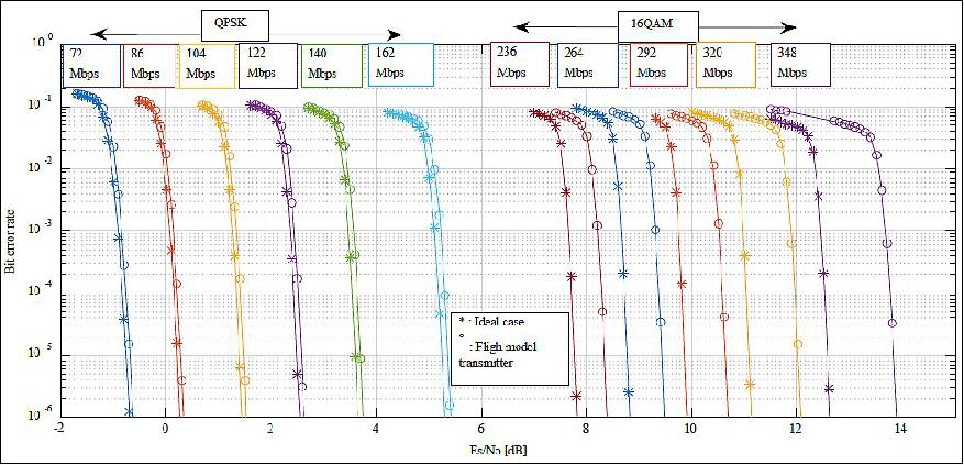
The symbol rate fs is selected as 100 Msps, taking into consideration the onboard digital hardware, frequency band allocation of 150 MHz, and the requirement for the data rates. We can change the data rate R (144-348 Mbit/s) by changing the coding rate r (0.36-0.87) or ACM 1-17. The performances of this high data rate downlink system shown in Fig.3 are simulated by the SPW (Signal Processing Work) system.
Let C be a received power at an input of a low noise amplifier at a ground station. Required C/No can be calculated as:
required C/No = (required Eb/No) x R
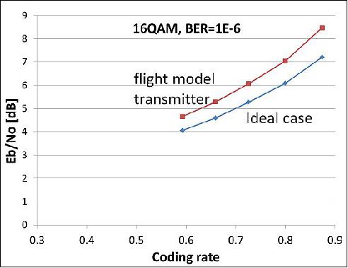
where R is a bit rate given as (symbol rate) x mod. multiplicity x (coding rate). In this system, the symbol rate is 100 Msps, and modulation multiplicity is 2 for QPSK and 4 for 16 QAM. The required Eb/No is given at 17) for ideal cases. The realistic required Eb/No value may be degraded due to nonlinearity of the transmitter and synchronization errors at the demodulation. Figure 4 shows the required Eb/No for bit error rate 10-6 with the ideal case as well as the flight model of the transmitter. In the latter case, we recorded the waveform of the transmitting signal from the flight model and added noises to the signal.
Onboard High-Speed Communication Instruments
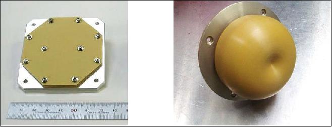
The onboard antenna for the high speed downlink of the Hodoyoshi-4 satellite is a medium gain antenna with 13.5 dBi gain and 2 x 2 patch array. Its beamwidth is about 20º and is directed toward a ground station with about 5º accuracy. The link calculation was performed for Hodoyoshi-4 for a 600 km altitude. Table 7 summarizes the link calculation. The link margins can be calculated based on the received C/No, the required Eb/No and the data rate.
Items | Values | Comments |
Satellite |
|
|
TX Power [dBW] | 3.0 | 2 W |
TX Cable Loss [dB] | -1.0 |
|
TX Antenna Gain [dBi] | 13.5 | MGA (Medium Gain Antenna) |
EIRP [dBW] | 15.5 |
|
Propagation |
|
|
Propagation Loss [dB] | -177.9 | Elevation = 5º (2320 km) |
(altitude 600km) | -173.9 | Elevation = 30º (1460 km) |
Rain & Atmospheric Loss [dB] | -2.1 | Inclusive noise |
Ground Station |
|
|
RX Antenna Gain [dBi] | 47.5 | 3.8 m diameter |
System Noise Temp [dBK] | 20.0 | 100 K |
G/T [dB/K] | 27.5 |
|
Received C/No [dBHz] | 91.6 | Elevation = 5º |
| 91.6 | Elevation = 30º |
GaN-HEMT Power Amplifier
X-band power amplifiers on satellites have widely used GaAs devices. Recently, GaN-HEMTs (High Electron Mobility Transistors) achieved high efficiencies as high frequency and power devices. The project has developed X-band GaN-HEMT amplifiers in order to reduce the power consumption.
Amplitude-phase modulation such as 16 QAM requires linearity of the RF amplifier. The project has developed an AB class and a F class power amplifier with GaN-HEMT devices. It is found that an AB class is more suitable for our purpose than F class.

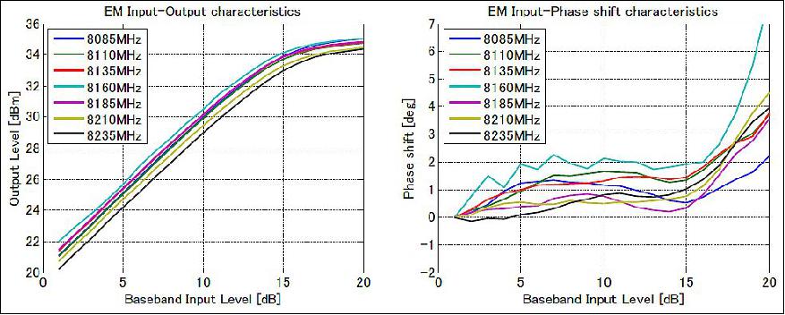
The AB class amplifier has saturated power of 35 dBm at 8160 MHz and output backoff is adjusted to 1-2 dB. The power added efficiency reaches to 47%. Figure 26 shows the input-output characteristics of AB class GaN-HEMT power amplifiers, AM-AM characteristics and AM-PM characteristics. The nonlinear phase change is less than 2º around the average output power level of 33-34 dBm, which is the operating point of the FM transmitter. This GaN-HEMT AB class amplifier is provided with both of high efficiency and small distortion characteristics.
X-Band Transmitter
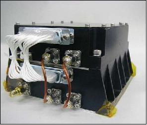
The project developed the 16 QAM onboard transmitter with the AB class GaN-HEMT power amplifier. As the block diagram in Fig.3 indicates, in a FPGA input baseband signals are mapped in a 16 QAM constellation and I, Q signals are pulse-shaping filtered. The clock frequency of the FPGAs reduces to 125 MHz with assists of 2.5 oversampling technique and parallel processing, even though the symbol rate is 100Msps.
It is found that the output power of the transmitter decreases by 1.2 dB at 50ºC,compared with one at 0ºC. This fact means that the output backoff or distortion characteristics change as the temperature changes. The project provided the transmitter with an automatic level controller that keeps the output backoff constant, in order to maintain an almost constant quality of the communication link.
The mass of the X-band transmitter is 1.3 kg and the power consumption is 22 W, which is significantly smaller, compared with the conventional products as indicated in Figure 23.
As an evaluation of the flight model of the X-band transmitter, the BER (Bit Error Rates) were measured without error corrections. Figure 29 is the measured and the ideal BER of 16 QAM. The measured bit error is degraded compared with the ideal one due to nonlinear effects of the amplifier on amplitude-phase modulation. Simulations indicate that SCCC of CCSDS.131.2-B-1 and turbo equalizer and decoder can improve the BER to less than 10-6 under the condition that the uncoded BER is less than 5 x 10⁻² at around Eb/No=10 dB. Figure 28 indicates that the uncoded BER is 2 x 10⁻² at Eb/No = 10 dB, which satisfies this condition of BER<10-6 with decoding and equalizing.
Frequency band | 8160 ± 60 MHz (X-band) |
RF output power | 2 W |
Symbol rate | 100 Msps (Mega Samples per second) |
Modulation schemes | - QPSK, 16QAM |
Data rate (user) | 72 to 540 Mbit/s |
Error correction code | SCCC (Serially Concatenated Convolutional Code) based on CCSDS 131.2-B-1 |
Data input interface | LVDS (Low Voltage Differential Signaling) |
DC power | 28 V, 22 W |
Instrument volume | 12 x 10 x 7.3 cm |
Instrument mass | 1.330 kg |
Operating temperature | -20º to +50ºC |
Radiation test | 20 kRad |

Ground Segment
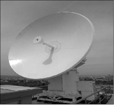
The operation and data reception of small satellites require a compact, low-cost ground station. The project developed an S/X dual band 3.8 m antenna at Sagamihara campus of JAXA/ISAS.
For the demodulation and decoding functions there are hardware system with FPGAs or gateways and a software system. For the former system realtime processing is possible. However, the required high performance hardware is expensive, in particular for the higher bit data rates of several 100 Mbit/s. On the other hand, the latter has merits of low cost of the hardware and flexibility of the software. The demerit is latency of processing. However, the downlink of earth observation data does not necessarily require realtime processing. In this high speed communication experiment, the received signals are demodulated and decoded with software processing after a visible pass period of the spacecraft.
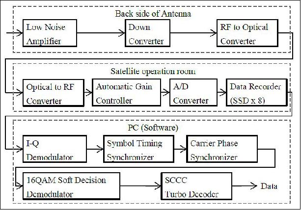
The integrated communication system complies with CCSDS 131.2-B-1 standard. Currently, the ground receiver only supports QPSK and 16 QAM modulation. Figure 32 shows the simulation results of the bit error rate. Nonlinearity and frequency dependence of the transmitter and receiver RF electronics causes an increase in BER (Bit Error Rate).When a BER 1 x 10⁻⁶ with margin of one decibel is required, then the communication system can transmit up to 32.5 GByte per pass from a sun-synchronous orbit with a 3.8 m ground antenna.
References
1) Yoshihiro Tsuruda, Yoshihide Aoyanagi, Toshiki Tanaka, Takeshi Matsumoto, Shinichi Nakasuka, Seiko Shirasaka, Masayasu Matsui, Ichiro Mase, "Demonstration of Innovative System Design for Twin Micro-Satellite: Hodoyoshi-3 and -4," Proceedings of the 30th ISTS (International Symposium on Space Technology and Science), Kobe-Hyogo, Japan, July 4-10, 2015, paper: 2015-f-12
2) Shinichi Nakasuka, "Current Status and Future Vision of Hodoyoshi Microsatellites – Systems for Quick and Affordable Space Utilizations," 2013, URL: http://unisec.jp/nanosat_symposium/images/report/pdf/nanosat_201311.pdf
3) Patrick Blau, "Dnepr - 2014 Cluster Launch," Spaceflight 101, June 10, 2014, URL: http://www.spaceflight101.com/dnepr-launch-updates---2014-cluster-launch.html
4) Masato Terakura, Kento Ohya, Hideaki Kogure, Yuichi Hiromori, Takehiko Kakizakai, Yoshihiro Kasuya, Hajime Kasahara, Shinichi Kimura, "Image Acquisition and Processing System using COTS Devices," Proceedings of the 29th ISTS (International Symposium on Space Technology and Science), Nagoya-Aichi, Japan, June 2-8, 2013, paper: 2013-f-24
5) Masato Terakura, Shinichi Kimura, "High-Performance Low-Cost Image Processing Unit for Small Satellite Earth Observation using COTS Devices,"IJETTCS (International Journal of Emerging Trends & Technology in Computer Science), ISSN 2278-6856, Volume 2, Issue 4, July-August 2013, URL: https://web.archive.org/web/20221129185253/https://www.ijettcs.org/Volume2Issue4/IJETTCS-2013-08-25-116.pdf
6) Information provided by Yoshihide Aoyanagi of The University of Tokyo, Tokyo, Japan.
7) Hirobumi Saito, Shinichi Nakasuka, "Micro satellite 'HODOYOSHI-4' success in the world-fastest downlink communication of 348Mbit per second as a 50kg-class satellite," UT School of Engineering, Feb. 18, 2015, URL: https://web.archive.org/web/20150522200536/http://www.t.u-tokyo.ac.jp/etpage/release/2015/150218_01.html
8) Hirobumi Saito, Tomoya Fukami, Hiromi Watanabe, Takahide Mizuno, Atsushi Tomiki, Naohiko Iwakiri, "World Fastest Communication from a 50kg Class Satellite -Micro satellite Hodoyoshi 4 Succeeds in 348 Mbit/s," IEICE (Institute of Electronics, Information and Communication Engineers) Communications Society – Global Newsletter, Vol. 39, No. 2, 2014, URL: http://www.isas.jaxa.jp/home/saito_hirobumi_lab/_src/sc1205/Saito20globalnewsltter.pdf
9) "Japanese microsatellites begin transmission of images," URL: http://tinyurl.com/qgoyzft
10) "Microsatellites 'Hodoyoshi-3 & 4' start capturing Earth images," University of Tokyo, July 31, 2014, URL: http://www.u-tokyo.ac.jp/en/utokyo-research/research-news/micro-satellites-hodoyoshi-3-4-start-capturing-earth-images/
11) Yoshihide Aoyanagi, Akira Iwasaki, Shinichi Nakasuka, Takuji Ebinuma, Shinichi Kimura, Tomohiro Narumi, "Result of Hodoyoshi-3 and -4 Earth Observation Missions," Proceedings of the 30th ISTS (International Symposium on Space Technology and Science), Kobe-Hyogo, Japan, July 4-10, 2015, paper: 2015-n-06
12) Hiroyuki Koizumi, Tadashi Inagaki, Taro Naoi, Yusuke Kasagi, Kimiya Komurasaki, Junichi Aoyyama, Koji Yamaguchi, "Development of the Miniature Ion Propulsion System: MIPS for the 50 kg Nanosatellite Hodoyoshi-4," Space Propulsion 2014, Cologne, Germany, May 19-22, 2014
13) Hiroyuki Koizumi, Kimiya Komurasaki, Junichi Aoyama, Koji Yamaguchi, "Engineering Model of the Miniature Ion Propulsion System for the Nanosatellite: Hodoyoshi-4," Transactions of JSASS (Japan Society for Aeronautical and Space Sciences and ISTS), Vol. 12, No. ISTS 29, pp. Tb_19-Tb_24, 2014
14) Hirobumi Saito, Naohiko Iwakiri , Atsushi Tomiki, Takahide Mizuno, Hiromi Watanabe, Tomoya Fukami, Osamu Shigeta, Hitoshi Nunomura, Yasuaki Kanda , Kaname Kojima, Takahiro Shinke, Toshiki Kumazawa, "High-Speed Downlink Communications with Hundreds Mbps from 50kg Class Small Satellites," Proceedings of the 63rd IAC (International Astronautical Congress), Naples, Italy, Oct. 1-5, 2012, paper: IAC-12-B2.3.1, URL of paper: http://www.isas.jaxa.jp/home/saito_hirobumi_lab/_src/sc1149/IAC2012.B2.3.1.pdf;URL of presentation: http://www.isas.jaxa.jp/home/saito_hirobumi_lab/_src/sc1150/IAC2012.B2.3.1PPT.pdf
15) Hirobumi Saito, Naohiko Iwakiri , Atsushi Tomiki, Takahide Mizuno, Hiromi Watanabe, Tomoya Fukami, Osamu Shigeta, Hitoshi Nunomura, Yasuaki Kanda , Kaname Kojima, Takahiro Shinke, Toshiki Kumazawa, "300 Mbps Downlink Communications from 50kg Class Small Satellites," Proceedings of the 27th AIAA/USU Conference, Small Satellite Constellations, Logan, Utah, USA, Aug. 10-15, 2013, paper: SSC13-II-2, URL: http://digitalcommons.usu.edu/cgi/viewcontent.cgi?filename=0&article=2919&context=smallsat&type=additional
16) Tomoya Fukami, Hiromi Watanabe, Hirobumi Saito , Atsushi Tomiki, Takahide Mizuno, Naohiko Iwakiri, Osamu Shigeta,Hitoshi Nunomura, Kaname Kojima, Takahiro Shinke, "Experiment of 348 Mbps downlink from 50kg class satellite," 10th IAA Symposium on Small Satellites for Earth Observation, Berlin, Germany, April 20-24, 2015, paper: IAA-B10-1302, URL of presentation: http://www.isas.jaxa.jp/home/saito_hirobumi_lab/_src/sc1194/IAA-B10-1302_web2.pdf
17) Massimo Bertinelli, "CCSDS 131.2-R-1 SCCC simulation baseline," Feb, 11, 2011, URL: http://tinyurl.com/opyl4bb
The information compiled and edited in this article was provided by Herbert J. Kramer from his documentation of: "Observation of the Earth and Its Environment: Survey of Missions and Sensors" (Springer Verlag) as well as many other sources after the publication of the 4th edition in 2002. - Comments and corrections to this article are always welcome for further updates (eoportal@symbios.space).
Overview Spacecraft Launch Mission Status Sensor Complement Communications sytem Ground Segment References Back to top